Introduction
The treatment of secondary complex post-traumatic midface deformities is particularly challenging.1 The conventional approach used in this type of reconstruction involves three steps. The first step is to recreate the original fractures by performing a series of osteotomies; the second step is to reposition the malpositioned segments in their normal anatomical alignment; and the third step is to fixate these segments with plates and screws. Unfortunately, this approach frequently produces less than ideal outcomes because the healed fracture lines and the post-traumatic bony contours distorted the normal anatomical reference points.
The advent of three-dimensional (3D) computer simulation has improved our ability to accurately assess the deformity and subsequently to develop a 3D surgical plan.2, 3 However, the transfer of the computerized surgical plan to the patient at the time of the surgery still poses a challenge. To this end, our Surgical Planning Laboratory has developed new techniques that have markedly improved our abilities to plan and treat patients who require distraction osteogenesis4, 5, orthognathic surgery2, 5, 6 and TMJ reconstruction7. These techniques involve the used of computer-generated templates and surgical navigation.
In patients with secondary posttraumatic midface deformities, we tried first to solve the transfer problem by using computer-generated templates. However, we found this technique often not to be feasible due to the limited surgical access and irregular surface geometry. We also tried to use surgical navigation, but the need for large navigational sensors to track the position of a multitude of small segments was too cumbersome. In addition, it was also extremely difficult to adapt and fix the plates while holding segments in their ideal position.
Eventually, we were able to solve this problem by creating a new technique that combines the use of prebent plates (templates) and navigation. It also reverses the steps of the conventional approach. The ultimate goal of this technique is to quickly and accurately place the displaced bony segments in their normal anatomical alignment. In our “reversed approach”, the new segment position is automatically attained. At the time of surgery, under navigation guidance, this is accomplished by pre-drilling the screw holes for the fixation plates prior to the osteotomies, and then by installing the pre-bent plates in these screw holes after the osteotomies have been completed. The prebent plates with the pre-drilled screw holes have all the information needed to accurately reposition the segments. The simple act of installing the plates automatically repositions the segments. This approach represents a new paradigm in skeletal midface reconstruction. The purpose of this paper is to present the protocol for this technique.
Technique
The ultimate goal of our technique is to accurately and quickly place the displaced bony segments in their normal anatomical alignment. As stated above, the conventional approach used to reconstruct malunions of the facial bones involves the completion of osteotomies, the manipulation of the displaced segments to their normal anatomical alignment and the fixation of these segments in their reduced position. In the conventional approach, the surgeon manually moves the displaced segments to their hypothetically “normal” position without having a clear frame of reference. This is a maneuver that is extremely difficult and that frequently results in poor outcomes. In our “reversed approach” the new segment position is automatically attain. At the time of surgery, under navigational guidance, this is accomplished by pre-drilling the screw holes for the fixation plates before any of the osteotomies. After the osteotomies have been completed, the pre-bent plates are then installed in these pre-drilled screw holes. The prebent plates together with the pre-drilled screw holes have all the information needed to accurately reposition the segments. The simple act of placing the prebent plates and tightening the screws automatically repositions the segments.
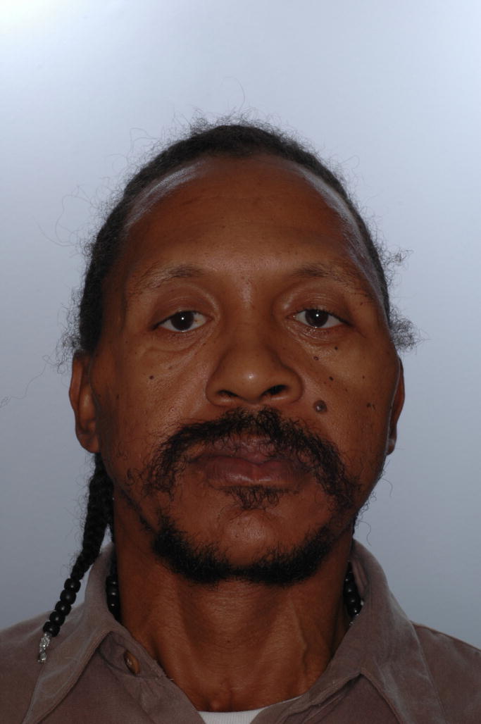
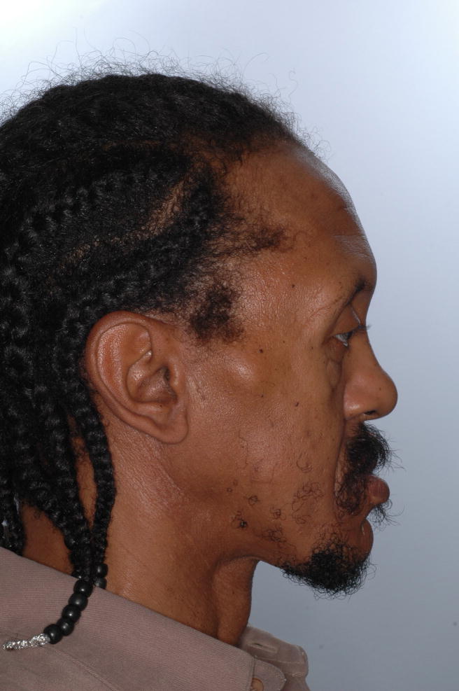
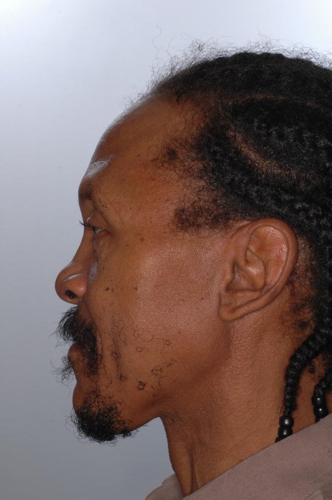
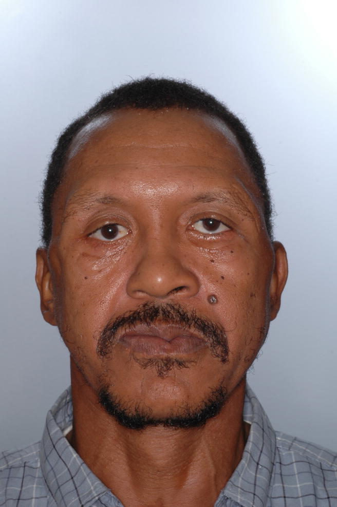
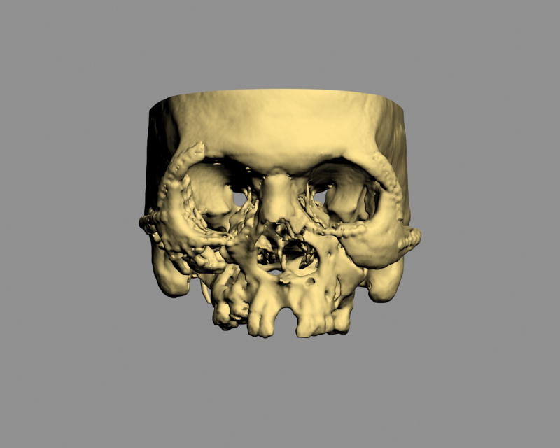
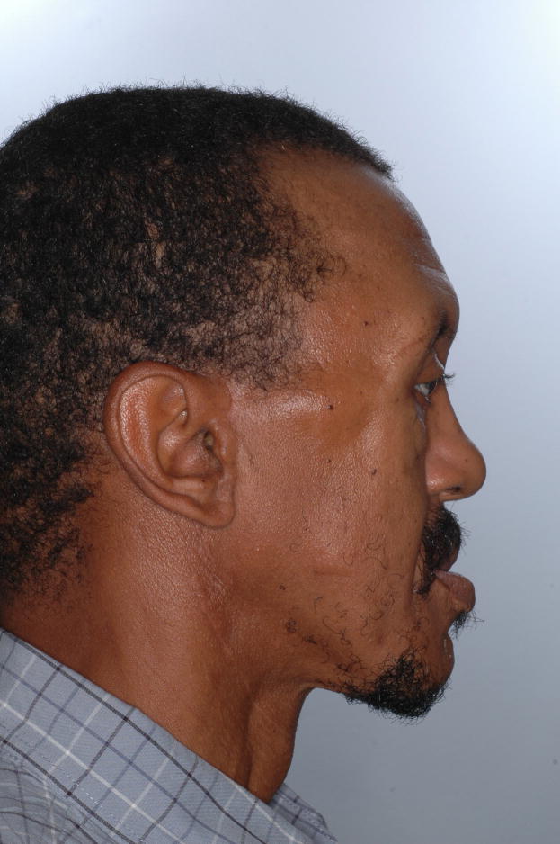
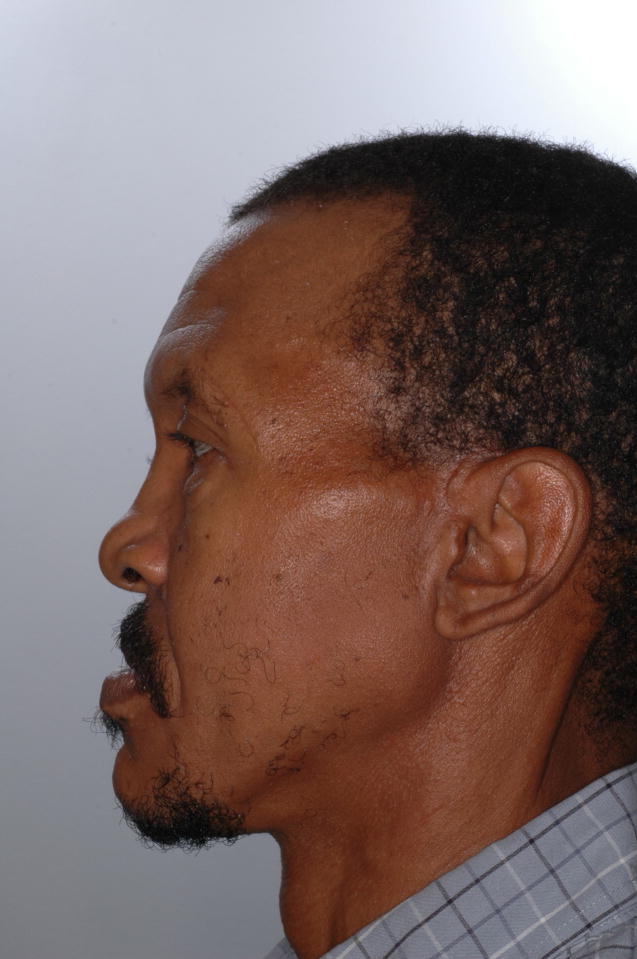
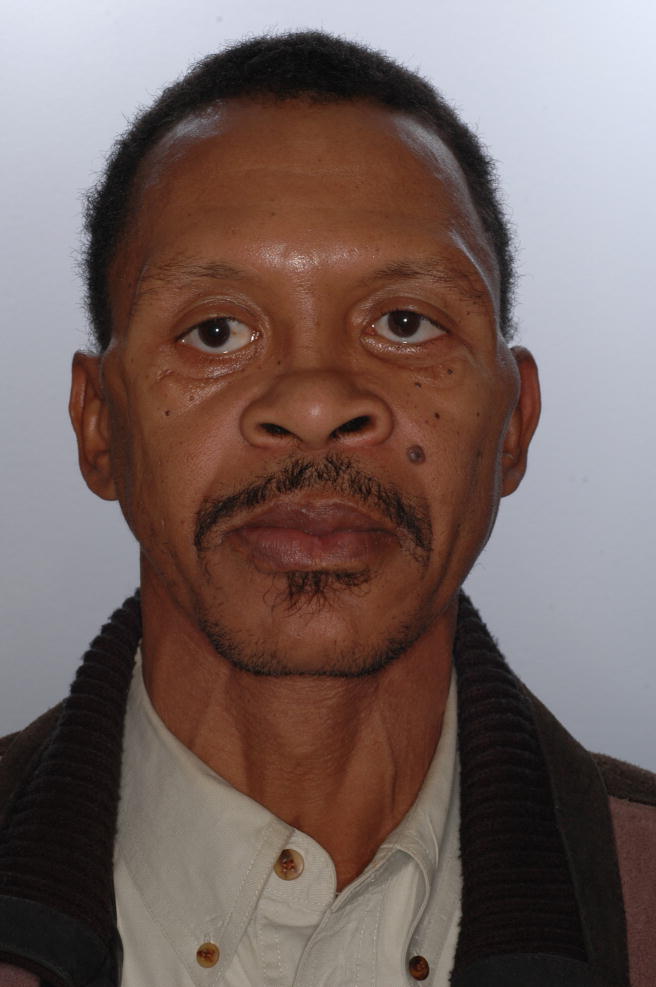
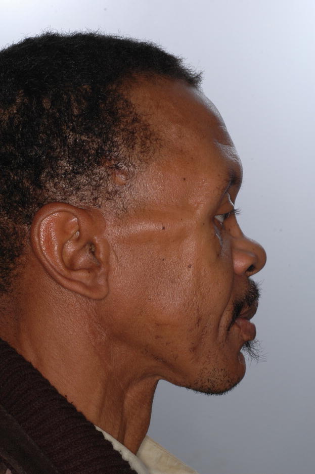
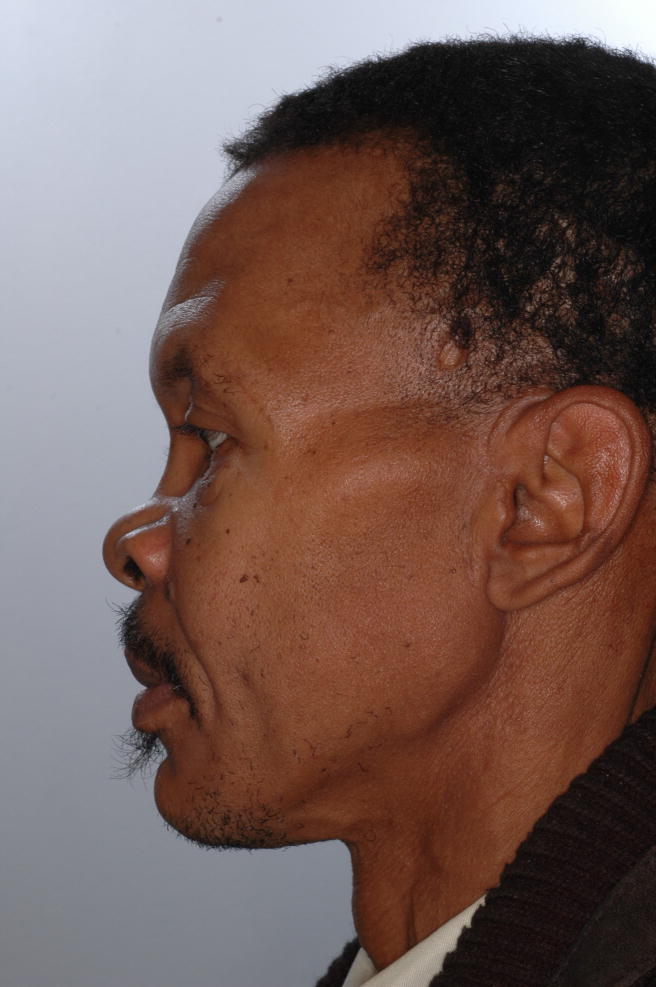
The protocol for our technique is illustrated in a patient who suffered significant malunion after treatment of panfacial fractures during a motor vehicle accident. His treatment plan entailed a staged three-part surgery: mandibular reconstruction, zygomaticomaxillary complex (ZMC) reconstruction and midface advancement. This protocol was employed in the second stage of the treatment plan which involved the reconstruction of both zygomas. His pre-operative photos are shown in Figure 1. This protocol is carried out is two phases. The first phase is the Planning Phase and the second one is the Implementation Phase.
Figure 1.
Pre-operative photos
a. Frontal view
b. Right view
c. Left View
Planning Phase
The purpose of the first phase is to develop a computerized treatment plan. To accomplish this, the surgery is simulated in the computer until the desired outcome is achieved. Custom planning software is utilized for this purpose.
The first step of the planning phase is to obtain a computed tomography (CT) scan of the maxillofacial skeleton. In our protocol, the CT scan is obtained at 1.25 mm slice thickness, 22 cm field-of-view, 0° gantry tile, 1:1 pitch, contiguous and non-overlapping slices.
The second step is to create a 3D computer model. The CT data is imported into the computer and the software is utilized to segment the CT data and to create a 3D model of the face. The 3D model is reconstructed using the Marching Cubes algorithm.8 This model is then oriented to the natural head position and the Nasion is positioned at the origin of the 3D coordinate system. This head position serves as a reference during the entire planning process.
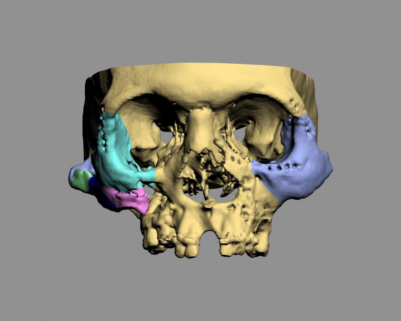
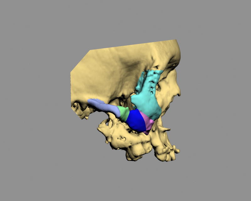
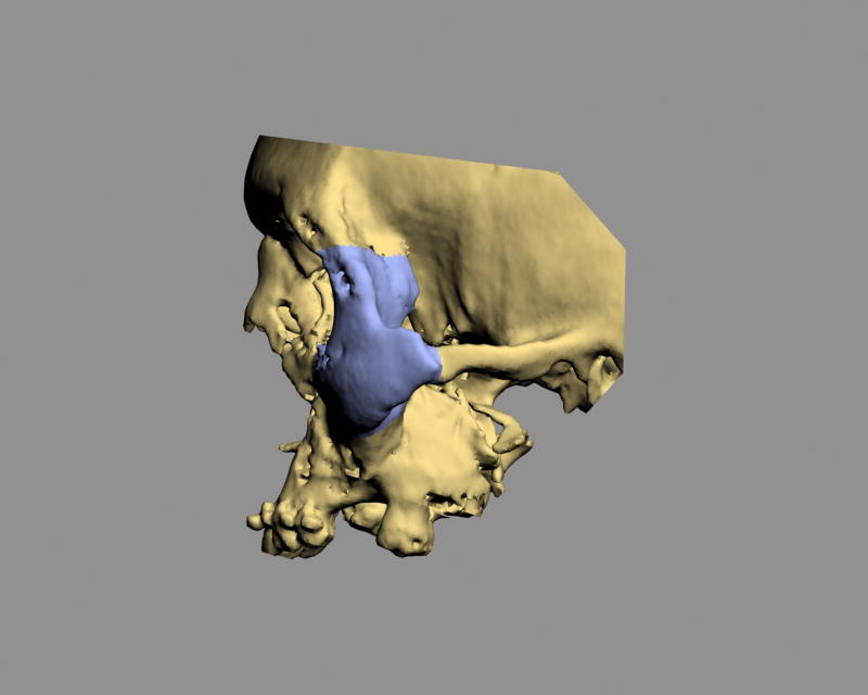
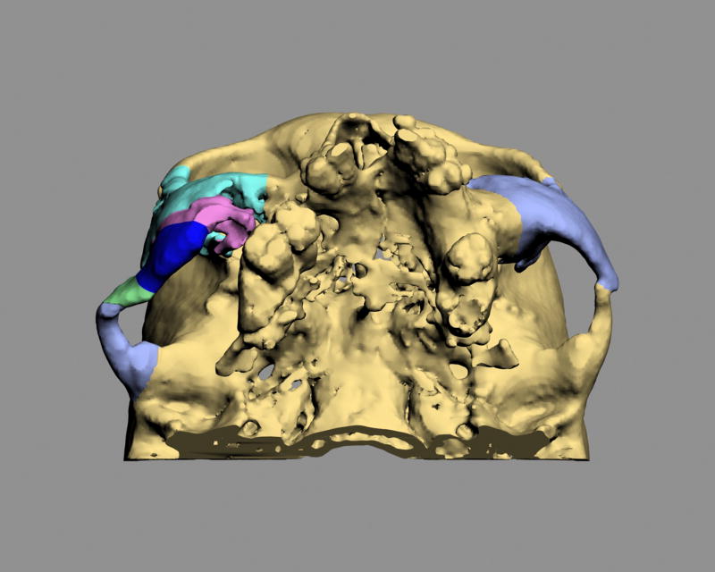
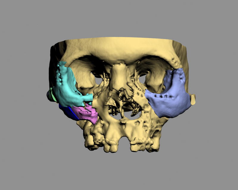
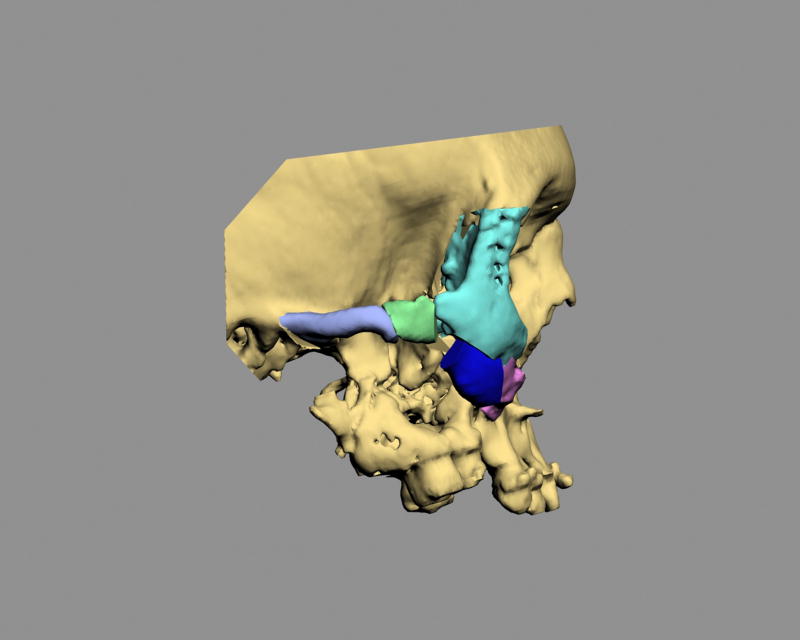
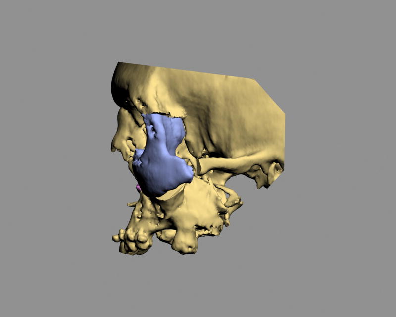
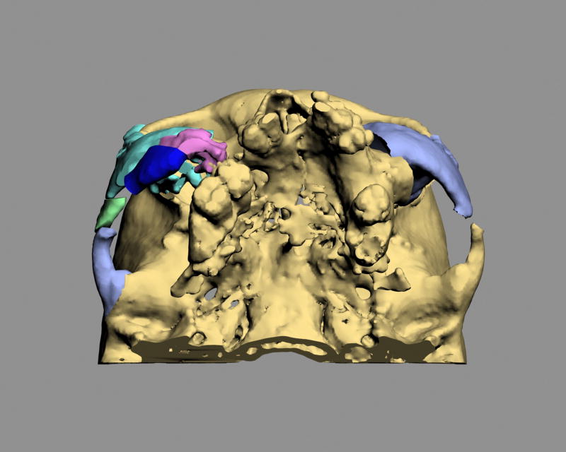
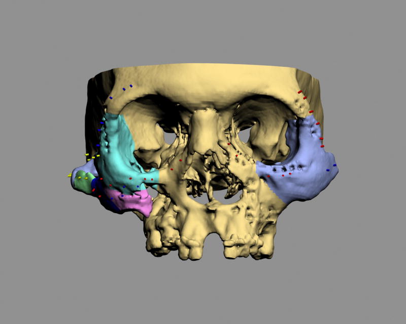
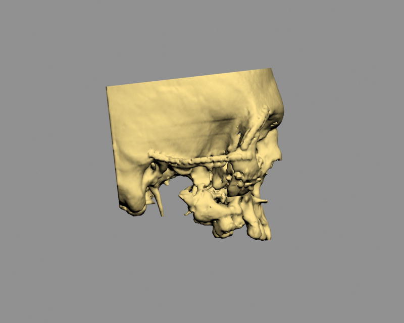
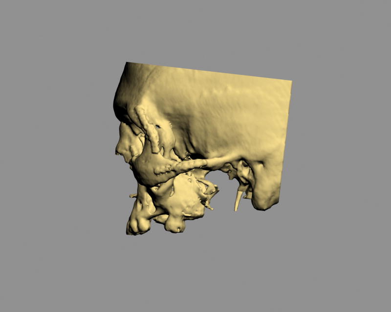
The third step is to recreate the original fractures and to move the displaced segments to their normal anatomical positions. The displaced bony segments can be separated from the rest of the skeleton by using segmentation or virtual osteotomy tools. In the software, each displaced bony segment becomes and individual object that can be colorized and named (Fig 2). Each displaced bony segment is then individually moved to its normal anatomical position (Fig 3). In unilateral deformities, the reduction can be facilitated by creating a mirror-imaged of the normal side which can be superimposed over the affected side to guide the reduction. Bilateral deformities are more challenging. They require an intimate knowledge of normal anatomy, together with the use of average dimensions, angulations and relationships.
Figure 2.
3D CT models depicting the original condition. Each displaced bony segment becomes and individual object has been colorized and named.
a. Frontal view
b. Right view
c. Left view
d. Bottom view
Figure 3.
3D CT models depicting the final planning outcome
a. Frontal view
b. Right view
c. Left view
d. Bottom view
The last step of this phase is to record the translational and rotational movements for each of the reduced bony segments (matrix). A given recording will measure the amount of millimeters that an object has moved along x, y and z axis, and the amount of degrees that it has rotated around the x, y and z axis. This information will be used later to move an object from its initial to its final position and vice versa.
Implementation Phase
This is the critical phase of the protocol. Some of the steps are completed preoperatively while the rest are performed intraoperatively. Prior to surgery, we need to complete three tasks: 1) prebend the titanium fixation plates that will be used at surgery; 2) predetermine the position of the screw holes for these plates; and 3) map the areas of collision between the bony segments
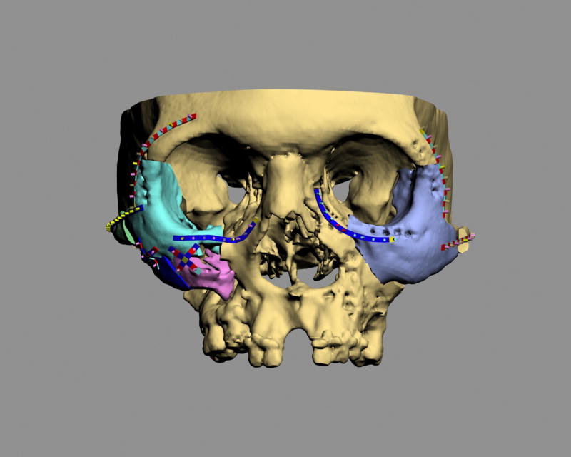
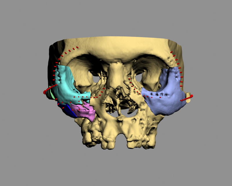
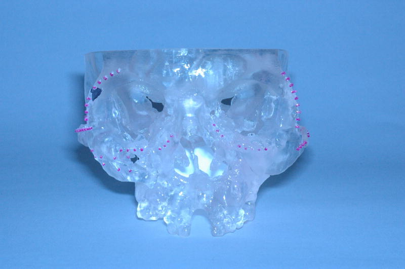
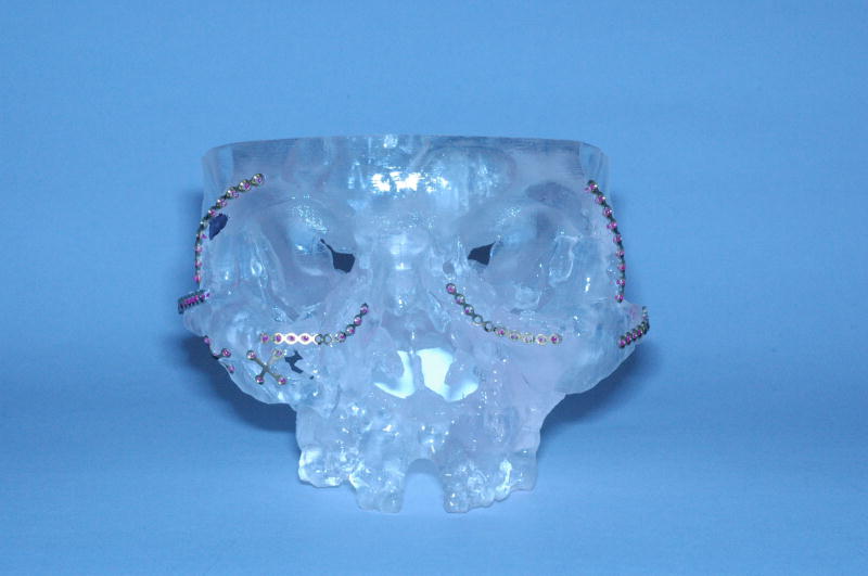
Prior to the surgery, we need to determine the appropriate plate size (i.e., 1.0 mm, 1.3 mm, 1.5 mm), shape (i.e., straight, curved, x-shape) and contour in order to prebend the titanium plates. To accomplish this, virtual replicas of all the surgical plates are generated in the computer. These virtual plates not only replicate the geometry of the actual plates but also replicate their material properties during bending (i.e., deformation). In addition, small virtual cylinders (2 mm in height and 1.0 mm in diameter) are attached to the virtual plates to replace the screw-holes. After each virtual plate with the virtual cylinders is created, they are adapted and installed to the three-dimensional computer model depicting the final planned outcome (Fig 4). The cylinders, which projects outwards, are placed on the surface of the bone and marked the position of each screw-hole (screw-hole markers). Subsequently, the virtual plates are removed from the bone, leaving the screw-hole markers on the bone (Fig 5). The resultant computer model, with the bony segments in the desired final position and the screw-hole markers in place, is used to fabricate a stereolithographic (STL) model (Fig 6). The STL model is then used as a template to help bend the titanium plates. The plates are adapted to the model aligning the screw-holes to the screw-hole markers (Fig 7).
Figure 4.
Virtual plates and screw-hole markers are adapted to the 3D CT model depicting the final planned outcome
a. Frontal view
b. Bottom view
Figure 5.
Screw-hole markers on the 3D CT model depicting the final planned outcome (Frontal view)
Figure 6.
A stereolithographic model of the 3D CT model depicting the final planned outcome and screw-hole markers (Frontal view)
Figure 7.
The titanium plates are adapted to the model aligning the screw-holes to the screw-hole markers (Frontal view)
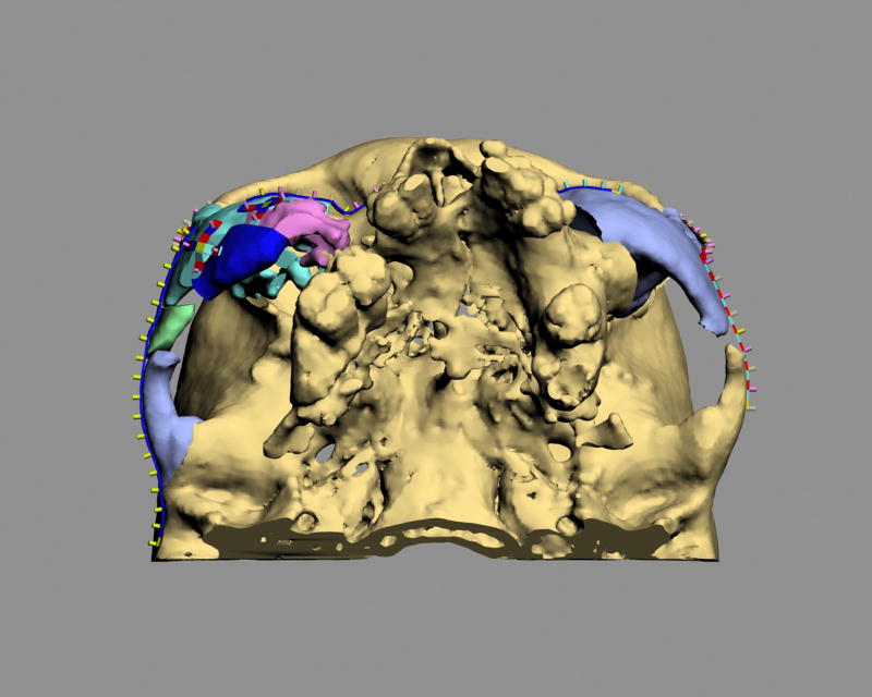
The next step is to determine the position of the screw-holes for the plates. This is done while the displaced bony segments are still malpositioned prior to the osteotomies. To determine the locations of the screw-holes prior to the osteotomies, we start with the computer model that depicts the planned final outcome and that has the screw-hole markers in place. We then command the software to “glue” the markers to their corresponding bony segments. Finally, we command the software to move the bony segments back to their original position carrying the markers with them. This creates a computer model of the initial deformity with the screw-hole markers in place (Fig 8). This model is then downloaded into the navigation computer that will be used during surgery to locate these holes (Fig 8).
Figure 8.
The 3D CT model of the original deformity with the selected screw-hole markers in place (Frontal view)
The final step that needs to be completed prior to surgery is to map the areas of collision between the bony segments. The treatment of malunions differs from the treatment of acute fractures because in malunions it is often necessary to remove bone to allow for appropriate reduction. In the conventional approach to midface reconstruction, the surgeon discovers areas of collision as he/she manipulates the segments into alignment. The amount of bone that needs to be removed is often unclear. As a result, the surgeon has to slowly remove bone at small increments until the segment can be aligned. This trial and error iterative approach is time consuming. In our protocol, we use computer simulation to record the areas of collision between the segments. The surgeon identifies areas of overlap between segments on the computer model of the planned final outcome. The overlapping areas are then mapped to their corresponding segments and transferred to the computer model of the original deformity. These areas are marked for excision and also downloaded to the navigation system. At the time of surgery, the surgeon will be able to excise all areas of collision before the segments are osteotomized and mobilized, reducing the length of the operation.
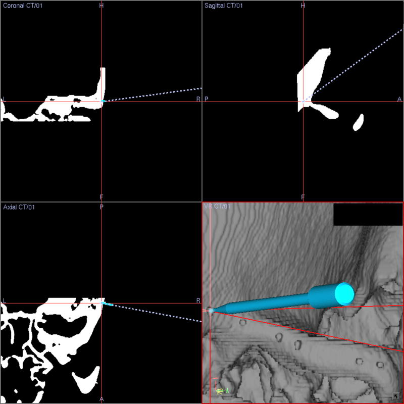
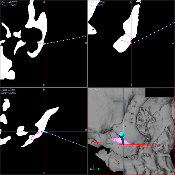
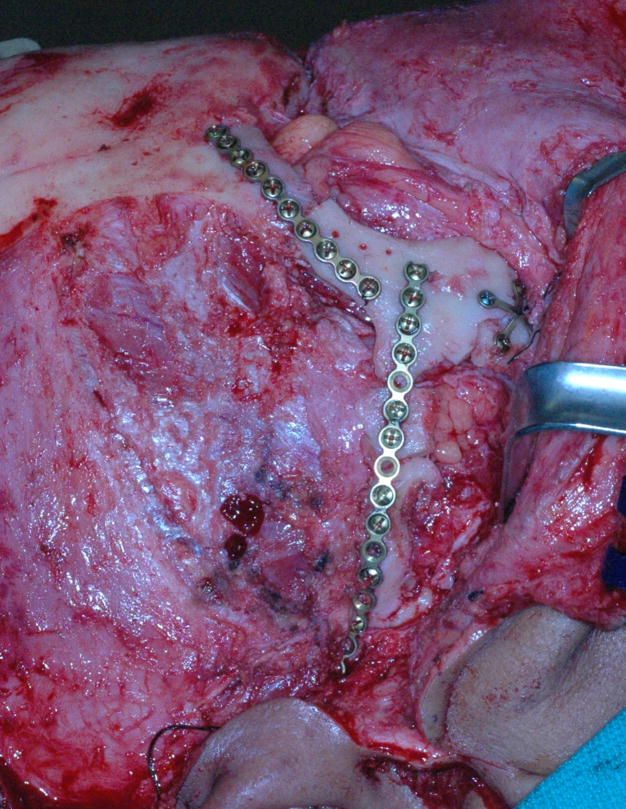
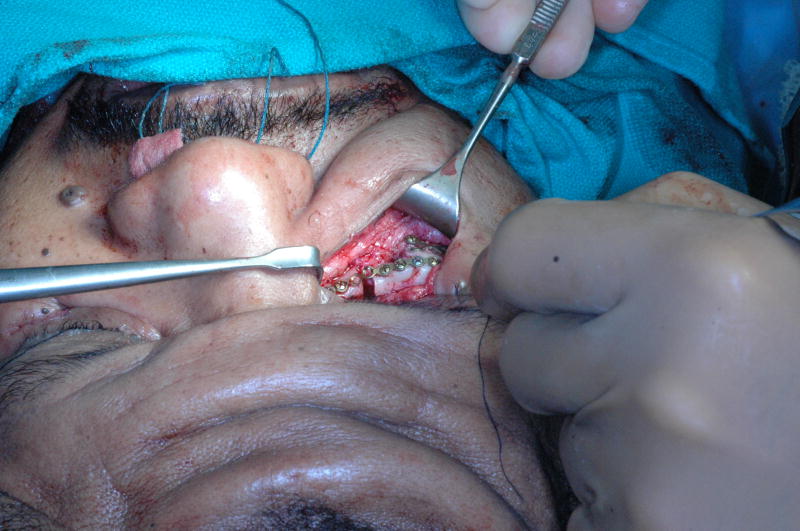
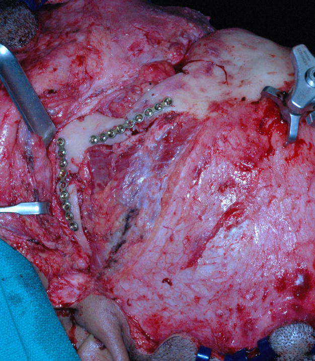
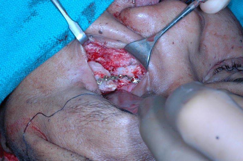
After all presurgical preparations are completed, the final part of the implementation phase in carried out at the time of surgery. After surgical exposure and prior to any osteotomies, navigational tracking sensors are attached to the skull and the surgical drill. The registration protocol for navigation is completed and the screw-holes are drilled under navigational guidance. Because the drill has a navigation sensor attached, the surgeon is able to visualize the tip of the drill on the screen. On the screen, the surgeon matches the position of the drill tip to the screw-hole marker and drills all the screw holes (Fig 9). Again under navigational guidance, the predicted areas of collision are then resected (Fig 10). Finally, the osteotomies are completed and the pre-bent plates are installed by placing screws in the appropriate screw holes. As the screws are tightened, the displaced bony segments are automatically reduced to the planned position (Fig 11).
Figure 9.
The position of the drill tip is matched to the screw-hole markers on the navigation screen to drill the screw holes.
Figure 10.
The predicted overlapping areas during the reduction (marked in pink) on the 3D model of the original deformity are excised under the guidance of surgical navigation.
Figure 11.
After the osteotomies are completed and the pre-bent plates are installed by placing screws in the appropriate screw holes. As the screws are tightened, the displaced bony segments are automatically reduced to the planned position.
a. Right view;
b. Top right oblique view;
c. Left view;
d. Top left oblique view.
The patient’s post-operative photographs and 3D CT models for this stage of the treatment are shown in Figure 12. The post-operative photos after midface advancement are shown in Figure 13.
Figure 12.
Post-operative photos and 3D models after zygomatic reconstruction
a. Frontal view (photo)
b. Frontal view (3D CT model)
c. Right view (photo)
d. Right view (3D CT model)
e. Left view (photo)
f. Left view (3D CT model)
Figure 13.
Post-operative photos after midface advancement
a. Frontal view
b. Right view
c. Left view
Discussion
The treatment of secondary complex post-traumatic midface deformities is particularly challenging. In many of these cases, the outcome is less than ideal. The problem is that healed fracture lines and distorted bony contours result in no anatomical frame of reference, making it difficult to accurately reposition the displaced segments. In order to solve this problem, some surgeons have used computer simulation, SLA models or intraoperative navigation.
Westendorff et al described the use of intraoperative navigation in unilateral zygomatic reconstruction.9 The surgery was planned in the computer using a mirror-image technique. Intraoperatively, frequently checked by the navigational pointer, the zygoma was gradually repositioned until the planned position was achieved. Surgical plates were then bent to stabilize the bony segments. Although this approach can produce good outcomes, it is difficult and time consuming. A major disadvantage is that one operator has to hold the bony segment while the other checks its 3D position with the navigational pointer. In an iterative fashion, the first operator moves the segment while the second operator keeps on checking its position until the desired final position is achieved. At this point, the first operator has to rigidly hold the segment while the second operator adapts and installs the plates. Another disadvantage of this technique is that it may be extremely difficult to perform when a multitude of bony segments need to be repositioned.
Marmulla et al used an approach that is similar to the one described above. Rather than using the navigation pointer to check the position of the displaced segment, they employed a second navigational tracker on each bony segment.10 The position of the displaced segment was visualized in real-time on the navigation screen. The advantage of this approach is that it facilitates the reduction process, obviating the need for multiple position checks by a second operator. The disadvantages are: 1) the displaced segment still needs to be manually held in a rigid position during fixation; 2) the navigation sensors are relatively large, limiting the space available for plates fixation11; and, 3) when multiple small segments are present, multiple navigation sensors are necessary, which is often physical impossible.
Baumann et al developed an interesting protocol for computer assisted treatment of zygomatic malunions.11 In this protocol, the surgery was planned on a stereolithography model. This model was first used to cut and to reposition the displaced zygoma. Afterwards, fixation plates were adapted and screwed. The plates were then removed and saved for surgery. The reduced zygoma was then returned to its original position, and a navigation system was used to record the positions of the screw holes. Intra-operatively, prior to the osteotomies, the navigation system was again used to drill the screw holes. After the osteotomies were completed, the bony segments were reduced by installing the prebent plates.
Although our protocol was developed independently, to some extent, it is clear that the above approach is similar to ours. The main difference is that in the author’s protocol, the operation is planned in the computer rather than on a stereolithography model. Computer planning, rather than using a SLA model, enables us to perform multiple iterations, measure orbital volumes, develop virtual plates and map areas of collision. It also avoids the need to navigate a SLA model to record the plan.
The main advantage of the “reversed approach” is that it allows for the predictable reduction of malpositioned segments in complex posttraumatic reconstructions. Unlike the other techniques, our protocol can be used not only to reposition a large bony segment (i.e. the zygoma), but also simultaneously reposition a multitude of displaced segments, even when they are very small. Another advantage is that at the time of surgery, the repositioning of the segments occurs automatically in a single step, eliminating multiple iterations. Surgical time, as well as the complexity of the surgery, are further reduced by allowing the removal of mapped areas of collision prior to the osteotomies. Finally, in our protocol, the whole planning process is completed in the computer using 3D imaging and CASS techniques. This allows the ability to perform multiple iterations to until the final plan is established, which is impossible in a SLA model. It also provides multiple tools that facilitate the planning process. Examples of these tools are mirror-imaging, superimposition of averaged normals, and linear, angular and volumetric measurements.
One of the disadvantages of this approach is that the preoperative planning time is increased. However, the time spent preoperatively does save time intra-operatively. Another disadvantage is that the protocol requires the used of expensive navigation hardware. Since this equipment is commonly used in neurosurgery and otolaryngology, it is usually available is most tertiary care hospitals. Finally, most maxillofacial surgeons are not yet familiar with 3D computer planning methods and surgical navigation.
Acknowledgments
The authors would like to thank Mr. Andrew M. Christensen, President and Chief Technical Officer; Mr. Nickolas M. Flannery, Chief Research Engineer; and Mr. Stephen M. Humphrise, ex-Director of Business Development at Medical Modeling Inc., Golden, CO for their technical support on this project.
This work was partially supported by NIH/NIDCR grants R41DE016171 and R42DE016171, and UT-Houston Medical School GCRC grant M01 RR002558 (NIH).
Footnotes
Publisher's Disclaimer: This is a PDF file of an unedited manuscript that has been accepted for publication. As a service to our customers we are providing this early version of the manuscript. The manuscript will undergo copyediting, typesetting, and review of the resulting proof before it is published in its final citable form. Please note that during the production process errors may be discovered which could affect the content, and all legal disclaimers that apply to the journal pertain.
References
- 1.Fuller SC, Strong EB. Computer applications in facial plastic and reconstructive surgery. Curr Opin Otolaryngol Head Neck Surg. 2007;15:233. doi: 10.1097/MOO.0b013e3281df2c5f. [DOI] [PubMed] [Google Scholar]
- 2.Gateno J, Xia JJ, Teichgraeber JF, et al. Clinical feasibility of computer-aided surgical simulation (CASS) in the treatment of complex cranio-maxillofacial deformities. J Oral Maxillofac Surg. 2007;65:728. doi: 10.1016/j.joms.2006.04.001. [DOI] [PubMed] [Google Scholar]
- 3.Xia J, Ip HH, Samman N, et al. Three-dimensional virtual-reality surgical planning and soft-tissue prediction for orthognathic surgery. IEEE Trans Inf Technol Biomed. 2001;5:97. doi: 10.1109/4233.924800. [DOI] [PubMed] [Google Scholar]
- 4.Gateno J, Teichgraeber JF, Xia JJ. Three-dimensional surgical planning for maxillary and midface distraction osteogenesis. J Craniofac Surg. 2003;14:833. doi: 10.1097/00001665-200311000-00004. [DOI] [PubMed] [Google Scholar]
- 5.Xia JJ, Gateno J, Teichgraeber JF. Three-dimensional computer-aided surgical simulation for maxillofacial surgery. Atlas Oral Maxillofac Surg Clin North Am. 2005;13:25. doi: 10.1016/j.cxom.2004.10.004. [DOI] [PubMed] [Google Scholar]
- 6.Xia JJ, Gateno J, Teichgraeber JF, et al. Accuracy of the computer-aided surgical simulation (CASS) system in the treatment of patients with complex craniomaxillofacial deformity: A pilot study. J Oral Maxillofac Surg. 2007;65:248. doi: 10.1016/j.joms.2006.10.005. [DOI] [PubMed] [Google Scholar]
- 7.Malis DD, Xia JJ, Gateno J, et al. New protocol for 1-stage treatment of temporomandibular joint ankylosis using surgical navigation. J Oral Maxillofac Surg. 2007;65:1843. doi: 10.1016/j.joms.2005.11.080. [DOI] [PubMed] [Google Scholar]
- 8.Cline HE, Lorensen WE, Ludke S, et al. Two algorithms for the three-dimensional reconstruction of tomograms. Med Phys. 1988;15:320. doi: 10.1118/1.596225. [DOI] [PubMed] [Google Scholar]
- 9.Westendorff C, Gulicher D, Dammann F, et al. Computer-assisted surgical treatment of orbitozygomatic fractures. J Craniofac Surg. 2006;17:837. doi: 10.1097/01.scs.0000221523.80292.93. [DOI] [PubMed] [Google Scholar]
- 10.Marmulla R, Niederdellmann H. Surgical planning of computer-assisted repositioning osteotomies. Plast Reconstr Surg. 1999;104:938. doi: 10.1097/00006534-199909040-00007. [DOI] [PubMed] [Google Scholar]
- 11.Baumann A, Schicho K, Klug C, et al. Computer-assisted navigational surgery in oral and maxillofacial surgery. Atlas Oral Maxillofac Surg Clin North Am. 2005;13:41. doi: 10.1016/j.cxom.2004.10.002. [DOI] [PubMed] [Google Scholar]


