

Abstract
Six of the seven iron atoms in the iron-molybdenum cofactor of nitrogenase display an unusual geometry, which is distorted from the tetrahedral geometry that is most common in iron-sulfur clusters. This distortion pulls the iron along one C3 axis of the tetrahedron toward a trigonal pyramid. The trigonal pyramidal coordination geometry is rare in four-coordinate transition metal complexes. In order to document this geometry in a systematic fashion in iron(II) chemistry, we have synthesized a range of four-coordinate iron(II) complexes that vary from tetrahedral to trigonal pyramidal. Continuous shape measures are used for a quantitative comparison of the stereochemistry of the Fe atoms in the iron-molybdenum cofactor with those of the presently and previously reported model complexes, as well as with those in polynuclear iron-sulfur compounds. This understanding of the iron coordination geometry is expected to assist in the design of synthetic models for intermediates in the nitrogenase catalytic cycle.
Introduction
Nitrogenase: Evidence for the importance of belt iron atoms
Nitrogenase enzymes perform the only known biological transformation of the N2 molecule.1 There are three very similar nitrogenase enzymes expressed by azatrophic microorganisms, and the major difference between these enzymes is in the metal composition, with iron-molybdenum nitrogenases better understood and more active than iron-vanadium and iron-only nitrogenases.2 Each enzyme has an eight-metal cluster at which N2 binds and is reduced with addition of protons, and the available evidence suggests that the clusters in the different enzymes are similar except for substitution of the heterometal (Fe7Mo in the “FeMoco,” Fe7V in the “FeVco,” and Fe8 in the “FeFeco”).3
Iron-molybdenum nitrogenases from C. pasteurianium, K. pneumoniae, and A. vinelandii have been characterized by crystallography,4 and the highest-resolution structure (1.16 Å) shows the constitution of the FeMoco to be Fe7MoS9X(homocitrate), where X is a central atom of the appropriate size and electron density to be C, N, or O.5 There is substantial controversy over the identity of X: ENDOR and ESEEM studies suggest that X is not N,6 but a range of theoretical studies find that N is most likely based on redox potentials, Mössbauer parameters, and Fe-X distances.7 Identifying the site at which N2 binds has also been controversial. N2 reactions are best-known and most efficient at molybdenum.8 However, the rates of reduction of substrates in mutant enzymes are most suggestive of substrate binding at the central (“belt”) iron atoms.9 The most convincing evidence in this regard is the fact that reducing the size of the amino acid Val-70 allows binding of substituted acetylenes with substituents that engage in hydrogen bonding to His-195 (residue numbering from the α subunit of A. vinelandii protein).10,11 Because acetylene reduction is inhibited by N2 in these mutants, this binding site is probably the same as that for N2.
Because of the likely role of the six belt iron atoms of the FeMoco in catalysis, chemists desire to understand them in detail. In the isolated, reduced cofactor, they exist as part of a mixed-valence Fe2+/Fe3+ cluster (MN),12 and the crystal structures invariably show that the geometry of each belt iron atom is distorted away from tetrahedral, with the iron atom near the plane of the three sulfur ligands. The Mössbauer parameters of the belt iron atoms suggests strong bonding to the three bridging sulfides, but a weak ionic interaction with X.13 We have speculated that further reduction of the cofactor could disrupt the Fe-X interaction, leading to N2 binding.14,15,16 Computational studies have not reached a consensus regarding the structural effects of reduction on the core of the cofactor.7 Spectroscopic studies using Extended X-ray Absoption Fine Structure (EXAFS) indicate that the average Fe-Fe distance contracts upon reduction, but (because of the complexity of the cofactor) do not give more detailed insight into bond forming/breaking.17 The geometry, distortions, and cooperative movements of the iron atoms in the FeMoco are likely to play an important role in the observed reactivity.
Structurally analogous synthetic complexes
Numerous synthetic iron complexes have been studied in order to provide a comparative basis for understanding the iron-molybdenum cofactor.18 However, no detailed analysis of the stereochemistry of its metal atoms has been undertaken, and that is a relevant piece of information that must be taken into account when trying to mimic the chemical activity of the active site in model complexes. We thus need to focus both in the local coordination geometry of the Fe atoms (that can be modeled by mononuclear compounds) and on the global shape of the Fe7Mo entity that can be modeled with polynuclear compounds. Because the belt iron atoms are coordinated to three bridging sulfides, in addition to a weak interaction with X, models of the local coordination geometry should include three strong donor ligands and one weaker bond. Complexes of this type are rare in the synthetic literature, because iron(II) chemistry is dominated by complexes with four or more strong donor ligands.
Iron-sulfur clusters make up one class of candidate compounds, and they are well-known in synthetic chemistry.19 In Fe4(μ3-S)4 clusters, iron atoms are coordinated by three sulfides, and the fourth position is typically occupied by a strongly bound ligand (e.g. chloride). In some cases, use of phosphines has led to “prismane” and “basket” clusters in which some iron atoms have a geometry that approach a trigonal pyramid.20 Power has also synthesized a tris-thiolatoiron(II) complex with no strong fourth donor, but which may have an agostic interaction of a C-H bond to the iron.21 Another interesting family is the octanuclear M2Fe6 complexes, with M = Mo or V and sulfido or thiolato bridges.22 In these clusters, the Fe atoms are four-coordinate and the global topology resembles that of FeMoco, with two M atoms capping an Fe6 core.
Recently, bulky β-diketiminate ligands (abbreviated LMe and LtBu, Scheme 1) have been used for stabilizing three-coordinate iron(II) complexes.23 In many cases, a fourth ligand can bind weakly.23e,f,h,i,k The bridging sulfide complex LtBuFe(μ-S)FeLtBu, which mimics a part of the cofactor, coordinates certain N-donor ligands such as acetonitrile, ammonia, and substituted hydrazines.24 However, it is not immediately clear how to compare the geometry of these synthetic complexes with the belt iron atoms of the FeMoco.
Scheme 1.

This paper describes our efforts to quantitatively describe the geometries of four-coordinate iron(II) complexes in order to provide a basis for comparison to the belt iron atoms of the FeMoco. This is intended to facilitate spectroscopic investigations that compare the iron-molybdenum cofactor to other compounds. Two methods are described: a simple but limited method based on L-M-L angles, and continuous shape measures that are adapted for effective evaluation of geometries near a trigonal pyramid. In order to provide a large set of synthetic complexes for comparison, we also report some new iron(II) β-diketiminate complexes.
Continuous Shape Measures
A brief description of continuous shape measures is presented in this section. More detailed information on this stereochemical tool and its applications to transition metal compounds can be found in a recent review.25 Continuous shape measures were proposed by Avnir and coworkers25,26 to provide a quantitative evaluation of the degree of distortion of a set of atoms (e.g., the coordination sphere of a transition metal) from a given ideal polyhedral shape. In short, the proposed method consists in finding the ideal structure having the desired shape that is closest to the observed structure. The ideal and real polyhedra are superimposed in such a way as to minimize the expression in eq 1, the value of which is the shape measure of the investigated structure Q relative to the ideal shape P, where q⃗i are N vectors that contain the 3N cartesian coordinates of the problem structure Q, p⃗i contain the coordinates of the ideal polyhedron P, and q⃗0 is the position vector of the geometric center that is chosen to be the same for the two polyhedra.
| (1) |
S(Q, P) = 0 corresponds to a structure Q fully coincident in shape with the reference polyhedron P, regardless of size and orientation. The maximum allowed value is S(Q, P) = 100, although in practice the values found for severely distorted chemical structures are very rarely larger than 40.
For the purpose of the present work, we can use shape measure S(tetrahedron) as a measure of the distortion of the Fe(ligand)4 groups from the tetrahedron,27 and S(vTBP) to measure the deviation of a structure to a vacant trigonal bipyramid (vTBP), defined as a trigonal pyramid with axial ligand-metal-basal ligand bond angles of 90°. We can also use shape measures to analyze the geometry of Fe6 cores in synthetic M2Fe6 complexes and compare them with that of the Fe7Mo group in the iron-molybdenum cofactor of nitrogenase.
An additional advantage of using the shape measures approach is that the minimal distortion pathway between two ideal polyhedra is analytically defined,28 and one can also calculate the distance of a given structure to such a pathway, via a path deviation function. In the present case, we will be able to tell whether a Fe(ligand)4 distorted tetrahedral structure falls along the pyramidalization path that takes a tetrahedron to a vTBP or by how much it deviates from such a path. Finally, the extent of transformation from one polyhedral shape to another is quantified through the use of a generalized interconversion coordinate, a percentage that shows how far a given structure has gone along the polyhedral interconversion path.27b
Results
Synthesis of four-coordinate iron(II) diketiminate complexes
The synthesis and characterization of some of the four-coordinate iron(II) diketiminate complexes analyzed here have been reported. These four-coordinate iron(II) diketiminate complexes are conveniently prepared by the addition of a donor ligand L′ (L′ = substituted pyridine or nitrile) to the appropriate free three-coordinate (LRFeX) or dimeric four-coordinate iron(II) precursor ([LRFe(μ-X)]2), (LR = bulky β-diketiminate ligand, X = halide, amide, hydrocarbyl, hydride; Scheme 1a).
Four new tetracoordinate iron(II) complexes LMeFeiBu(tBuCN) (1), LMeFeCH2tBu(tBuCN) (2), LMeFeCl(4-tBu-py) (3) and LtBuFeCl(CH3CN) (4) have been prepared by the route shown in Scheme 1a. The neutral donor (trimethylacetonitrile, 4-tert-butylpyridine or acetonitrile) was mixed with a three-coordinate hydrocarbyl complex, chloride complex LMeFe(μ-Cl)2Li(THF)2 (Scheme 1b), or chloride complex LtBuFeCl. Thermal-ellipsoid plots of the X-ray crystal structures of 1, 2, 3 and 4 are presented in Figures 2 and 3 (see also Table 1).
Figure 2.

Examples of four-coordinate iron(II) diketiminate complexes with trigonal pyramidal distortions. Molecular structures of the new complexes LMeFeiBu(tBuCN) (1) (a) and LMeFeCH2tBu(tBuCN) (2) (b). Thermal ellipsoids shown at 50% probability, with hydrogen atoms omitted for clarity. The pseudoapical (axial) position in each complex is occupied by the neutral ligand trimethylacetonitrile (L′).
Figure 3.

Molecular structures of the new four-coordinate diketiminate iron(II) chloride complexes LMeFeCl(4-tBu-py) (3) and LtBuFeCl(CH3CN) (4). Thermal ellipsoids drawn at 50% probability, hydrogen atoms are omitted for clarity. The pseudoapical (axial) positions are occupied by 4-tert-butylpyridine and acetonitrile, respectively.
Table 1.
Selected bond distances (Å) and angles (°) for new tetracoordinate iron(II) complexes.
| Compound | LMeFeiBu(tBuCN) (1) | LMe FeCH2tBu (tBuCN) (2) | LMeFeCl(4-tBupy) (3) a | LtBu FeCl(CH3CN) (4)a | LtBuFe(η2- OTf) (5) |
|---|---|---|---|---|---|
| Fe-X | 2.040(2) | 2.053(2) | 2.237(1), 2.238(1) | 2.222(2), 2.247(2) | 2.131(3) |
| Fe-L′ | 2.163(2) | 2.151(2) | 2.106(2), 2.110(3) | 2.089(6), 2.082(6) | 2.213(3) |
| Fe- N(diketimine) | 2.023(1), 2.026(1) | 2.027(1), 2.029(1) | 2.004(2), 2.007(2) 1.999(2), 2.010(3) |
1.996(5), 2.001(4) 2.000(4), 2.002(5) |
1.959(3), 1.961(3) |
| (N2X)plane···Feb | 0.3680(9) | 0.4737(9) | 0.525(1), 0.522(1) | 0.469(2), 0.534(2) | 0.501(2), 0.404(2) |
| C(Ar)-N-Cα(LMe)c | 119.5(1), 120.8(1) | 121.0(1), 119.0(1) | 120.5(2), 119.5(2) 120.7(3), 119.5(3) |
126.3(5), 125.1(5) | 128.7(3), 125.9(3) |
| N-Fe-N (bite angle) | 92.74(5) | 92.81(5) | 94.5(1), 93.5(1) | 98.0(2), 96.5(2) | 95.6(1) |
| Σ(∠L–Fe–L)d | 646.8(3) | 648.3(3) | 654.7(5), 654.5(5) | 653(1), 657(1) | 658.3(7) |
| ∠(LRFe)–(FeXL′)e | 89.62(4) | 89.96(5) | 89.91(7), 89.63(7) | 88.1(1), 82.2(1) | 84.2(1) |
Two independent molecules were found in the unit cell.
Minimum distance between iron and the plane formed by the three basal ligands.
Angle around the imine nitrogen.
Sum of angles around iron.
Twist angle between the C3N2Fe plane (iron(II) diketiminate plane) and the FeXL′ plane.
Structurally characterized tetracoordinate iron complexes with hydrocarbyl ligands are rare.29,30,31,32 The iron-carbon bond distances for 1 (2.040(2) Å) and 2 (2.053(2) Å) are similar to those observed in other four-coordinate complexes of iron(II) with sp3-hydrocarbyl ligands, which range between 2.032 and 2.120 Å.29 The iron-carbon bond distances in 1 and 2 are similar to those in the three-coordinate analogues (2.003–2.060 Å),23 despite the higher coordination number.
The Fe-Cl distances in the four-coordinate chloride complexes 3 (2.237(1), 2.238(1) Å) and 4 (2.222(2), 2.247(2) Å) are intermediate between the iron-chloride bond distance in the three-coordinate complex LtBuFeCl 2.172(1) Å and the Fe-Cl bond distances in the chloride-bridged four-coordinate complexes LMeFe(μ-Cl)2Li(ether)2 (2.324 to 2.343 Å, ether = Et2O or THF), [LMeFe(μ-Cl)]2 (2.3583(5), 2.4045(5) Å) and [Mg(THF)4][LMeFeCl(μ-Cl)]2 (Fe-(μ-Cl) 2.377(1), Fe-Cl 2.267(1) Å).23a Thus, the iron-chloride bond distance is severely affected by both the coordination number at iron and the hapticity of the chloride ligand itself.
A number of four-coordinate iron(II) diketiminate complexes containing two virtually identical ligands, e.g. LMeFeCl2Li(THF)2, [LMeFe(μ-Cl)]2 and [LMeFe(μ-F)]2 (Scheme 1b–1c) have been reported. In new work, the chelated complex LtBuFe(η2-OTf) (5, η2-OTf = O,O-η2-O3SCF3−) (Scheme 1d) has been synthesized as described in the Experimental Section and crystallographically characterized. The molecular structure is shown in Figure 4.
Figure 4.
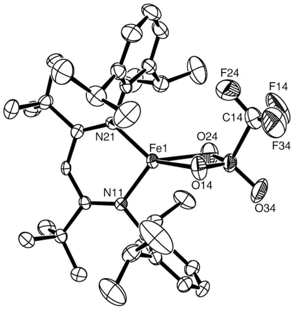
Thermal-ellipsoid plot of the X-ray crystal structure of LtBuFe(η2-OTf) (5). Thermal ellipsoids shown at 50% probability. Hydrogen atoms are omitted for clarity.
The triflate (trifluoromethanesulfonate) complex LtBuFe(η2-OTf) (6, OTf = O3SCF3, Figure 4) can be made in low yields by the metathesis reaction of LtBuFeCl with LiOTf, or by the disproportionation reaction between LtBuFeNNFeLtBu and LtBu Fe(OTf)2 in a 1:2 ratio. However, the highest-yielding synthesis of 3 involves direct deprotonation of lutidinium triflate (2,6-(CH3)2C6H3NHOTf) with the hydride complex [LtBuFe(μ-H)]2 (Scheme 1d). Because the triflate anion is weakly coordinating, it is an excellent leaving group. Thus, triflate complexes such as 5 are potentially useful in catalysis and as synthetic precursors to other complexes.33 There are no crystal structures reported for iron complexes where triflate acts as a bidentate (dihapto) ligand.29,34 Moreover, none of the reported iron triflate structures is four-coordinate. Thus, complex 5 is an unprecedented example of η2-triflate ligation to low-coordinate iron. The molecular structure of 5 (Figure 4) reveals that the FeO2 core is somewhat asymmetric, with Fe-O distances that differ by 0.082(4) Å (Table 1).
All of the four-coordinate iron(II) diketiminate complexes contain a high spin iron(II) center, consistent with the broad, paramagnetically shifted signals in their 1H NMR spectra. Their solution magnetic moments (Evans)35 are 4.5–5.5 μB, in agreement with a high spin d6 electronic configuration having four unpaired electrons and a spin state of S = 2.
In compounds 1–5, the structural parameters of the diketiminate ligand closely resemble those observed for other iron(II) diketiminate complexes: the diketiminate bite angles (N-Fe-N) range from 92° to 98° and the Fe-N(diketiminate) bond distances range from 1.95 to 2.03 Å (Table 1). The C(Ar)-N-Cα angle around the diketiminate nitrogen atoms strongly depends on the bulk of the diketiminate, typically being around 120° for LMe, and approximately 7° to 9° wider for LtBu. Accordingly, this angle is 119–121° in 1–3 (containing LMe), and 125–129° in 3–5 (containing LtBu) (Table 1).
Perhaps the most striking structural feature among all the aforementioned four coordinate iron(II) complexes is the flexibility of the coordination geometry around iron. Thus, compounds with two identical monodentate ligands such as [LMeFe(μ-F)]2, [LMeFe(μ-Cl)]2, or LMeFe(μ-Cl)2Li(Et2O)2, appear to have structures that differ from tetrahedral only by virtue of the chelating ligand (Scheme 2b). In contrast, in some four-coordinate adducts such as LtBuFeH(4-tBu-py), LMeFeF(4-tBu-py) and LMeFeCl(tBupy) (3), the iron center deviates substantially from a tetrahedral geometry. Their idealized geometry is closer to a trigonal pyramid (Scheme 2e) characterized by axial ligand-metal-basal ligand bond angles α and basal ligand-metal-basal ligand bond angles β, retaining an approximate C3v symmetry. Different degrees of pyramidalization, gauged by the average α values, can be anticipated for the experimental structures, between 109.5° for the tetrahedron and 90° when the metal atom is coplanar with the three basal donor atoms. Therefore, we can consider the extreme of such distortion to be a trigonal bipyramid with one vacant axial position (vTBP, Scheme 2f).
Scheme 2.

On the other hand, we must not forget that the chelating nature of the diketiminate ligands imposes a small N-Fe-N bond angle compared to the ideal tetrahedral angle (ω, Scheme 2b). In the absence of the umbrella distortion leading to a trigonal pyramid, chelation results in a distortion to a C2v structure, independently of the values adopted by the bite angle ω. In real structures, both the umbrella and chelating distortions of the tetrahedron may appear simultaneously (Scheme 2c), with the eventual addition of a rocking distortion (Scheme 2d). Therefore, some quantitative measures are necessary to distinguish whether the tetrahedron or the vTBP best represents the coordination geometry in a given complex, and which angular parameters (α and β, or ω and γ) can better describe a particular structure.
Discussion
Quantitative measures of the geometry at four-coordinate metals
Traditional methods of analyzing geometries of metal centers are based on bond angles and mathematical manipulations thereof. This strategy led some of us to introduce an angle-based parameter τ.24,36,37 In four-coordinate complexes, τ is the normalized difference between the sum of the basal ligand-basal ligand angles and the sum of the basal ligand-axial ligand angles:
| (1) |
Using eq 1, an ideal tetrahedron has τ = 0, and an ideal vacant trigonal bipyramid has τ = 1. To identify which is the axial ligand, τ is calculated individually as if each of the four ligands were axial, and the largest value is used. This strategy is useful in defining a particular ligand as axial, which is effective if one choice of τ is larger by 0.1 or more.
The parameter τ was used to describe where a structure falls along the interconversion path between a tetrahedral geometry (α = β and τ = 0) and a vTBP geometry (α = 90°, β = 120° and τ = 1) shown in Scheme 2 (a, e and f). Using this measure, the belt iron atoms of the FeMoco have τ = 0.46 ± 0.03, with X in the axial position (throughout the paper, we use PDB 1M1N, with 1.16 Å resolution,4e in which there are 4 crystallographically independent FeMoco clusters, giving 24 belt iron atoms). This indicates that the belt iron atoms are about halfway between a tetrahedron and an axially vacant trigonal bipyramid.
In our earlier work, τ values were given for a number of model complexes.24 However, the τ parameter is limited: it is only appropriate for structures that lie near the interconversion path between a perfect tetrahedron and a perfect vTBP, and does not account for distortions that are not symmetric about the C3 axis of a tetrahedron, such as the chelation shown in Scheme 2b. As an example, consider two extreme cases: the square planar and sawhorse structures. The first one would have τ = 0 but clearly is not a tetrahedron, while the second one has τ = 1 even if it is not a vTBP. Although these are extreme cases, they tell us that structures that are intermediate between the tetrahedron and one of these shapes will have τ values that do not reflect a degree of pyramidalization of a tetrahedron. These limitations led us to seek a more general yet accurate method for defining four-coordinate geometries.
Using shape measures to define the geometry of four-coordinate complexes
A more discerning method for defining four-coordinate geometries is through the use of continuous shape measures described above. For the specific case of four-coordinate MX4 groups, the tetrahedral shape measure, S(tetrahedron), indicates how much that group deviates from a perfect tetrahedron. Hence, S(tetrahedron) values close to zero indicate nearly perfect tetrahedra, and higher values reflect increasingly strong distortions. Although the stereochemistry of four-coordinate metal complexes has been the subject of much concern in the last decades,38 the recent application of continuous shape measures has provided a new perspective and a more comprehensive description of the relationship between stereochemistry and electron configuration.25 Because square-planar and tetrahedral geometries are most common for four-coordinate complexes, it has been convenient to graphically describe the geometry of a given four-coordinate complex by plotting its shape measures with respect to a planar square, S(square), and to a tetrahedron, S(tetrahedron).27,39 A number of related complexes are plotted in this way, together with model structures, to give a shape map. Figure 5 shows shape maps for several families of four-coordinate Fe centers. It is evident that most of the experimental structures are very far from the square-planar geometry. On the other hand, it can be seen that the families of iron-sulfur clusters and of iron diketiminate complexes (Figure 5b, c) present a wider range of distortions than the belt iron atoms in FeMoco (Figure 5a). While the latter seem to concentrate near the tetrahedral shape, many members of the two other families seem to present distortions close to the spread or twist paths that take a tetrahedron to the square planar or chelated rectangular geometries, respectively.27,40 Since the iron sites in FeMoco do not follow the path to the square, but rather seem to present an umbrella distortion (Scheme 2e) that would ultimately lead to a vTBP shape (Scheme 2f), we choose an alternative shape map in which the two reference shapes are the regular tetrahedron and the vTBP.
Figure 5. Shape maps.

that display the range of geometries available to a type of complex; the x-coordinate of each point represents how close it is to an idealized tetrahedron, and the y-coordinate represents how close it is to an idealized square planar geometry. The three plots show the Fe atoms of the Fe-Mo cofactor (a), sulfur-bridged Fen clusters (b) and mononuclear diketiminate Fe complexes (c). The continuous line represents the minimal distortion path for the interconversion of the tetrahedron and the square.
Before analyzing the experimental structural data, let us briefly describe what can we expect in such a shape map, with the help of model tetracoordinate structures (Figure 6). The points shown on the two coordinate axes correspond to the ideal tetrahedral and vTBP shapes (with all metal-ligand bond distances the same), as indicated, and the curve connecting those two points (a in Figure 6) represents the minimum distortion interconversion path that corresponds to varying the Lax-M-Lbasal bond angles α from 109.5 to 90°. If we close only one of the basal bond angles (N-Fe-N) keeping a constant degree of pyramidalization (Scheme 2e–c) as would happen in the presence of a chelating diketiminate ligand, the structures follow a line approximately perpendicular to the minimal distortion path (b in Figure 6), while opening one basal angle results in a practically coincident line in the shape map. Then, if we add a bond distance distortion to a structure with a given degree of pyramidalization and with a fixed chelating angle, to represent the situation for the belt Fe atoms of the FeMo cofactor with three longer (Fe-S) and one shorter (Fe-X) bonds, a displacement in the direction c results.
Figure 6.

Paths in the tetrahedron-vTBP shape map corresponding to (a) the umbrella distortion that interconverts those two polyhedra (Scheme 2e and 2f), (b) the decrease in the basal N-Fe-N bond angle ω for a structure with α = 102° (α = average basal-metal-apical angle, Scheme 2c and 2e) and (c) a distortion leading to one short and three long bond distances, in a 1:1.26 ratio.
Using shape measures to describe the belt iron atoms of the FeMoco
The Fe7Mo cluster has the shape of an Fe6 trigonal prism, capped on its triangular faces by one Fe and one Mo atoms (Figure 7).41 The inner iron atoms can be separated into two subgroups, depending on whether they are closer to a capping Mo or Fe atom. All of them form FeXS3 trigonal pyramids (X being the atom that centers the trigonal prism) with X-Fe-S bond angles between 101 and 103°. The position of these Fe atoms in the shape map (Figure 8) clearly show them to be approximately halfway (between 55 and 62%, according to the generalized polyhedral interconversion coordinates described elsewhere27b) along the interconversion path between the tetrahedron and the vTBP (continuous line in Figure 8, i.e., path a of Figure 6), in agreement with the description provided by the τ parameter. However, we notice also that the coordination geometries of the Fe atoms progressively deviate from the pyramidalization path as the distortion of the tetrahedron increases (i.e., from bottom to top in Figure 8). Such a deviation can be attributed mostly to the combined effects of a chelating distortion (Scheme 2b) and bond distance inequality that show up as deviations from the path a along directions parallel to b and c in Figure 6. Effectively, a detailed analysis of the structure of the iron-molybdenum cluster shows that one basal edge of each Fe-centered pyramid is constrained by the capping FeS2 or MoS2 groups to S-Fe-S bond angles in the range 105–111°, while the other two basal angles are more flexible and can adapt to the larger values required by a pyramidalization distortion (115° < S-Fe-S < 123°). The belt Fe atoms have slightly different geometries on the Fe-capped and Mo-capped sides of the cofactor, with those on the Mo side showing a greater variety of shape measures, apparently following a well defined trend.
Figure 7.

Schematic depiction of the structure of the Fe7Mo site in FeMoco, showing the trigonal prism formed by the belt Fe atoms (the sticks do not represent chemical bonds) and the local XFeS3 coordination sphere of one of these atoms, with the other Fe-S and Fe-X bonds omitted for simplicity. Fe = orange, S = yellow, Mo = blue.
Figure 8.

Tetrahedron-vTBP shape map showing the position of the coordination spheres of the belt Fe atoms in FeMoco. The blue circles correspond to the belt Fe atoms at the Mo side, empty triangles to those at the capping Fe side. The continuous line represents the minimal distortion path between the tetrahedron and the vTBP, and the dotted line corresponds to the closing of one basal S-Fe-S bond angle in a XFeS3 model with α = 102° (Scheme 2e and 2c).
There is an excellent correlation between the tetrahedral shape measure and the deviation from the tetrahedron-vTBP path (Fig. 9). The belt sites at the Fe (black squares) and Mo (blue circles) sides of the cluster follow essentially the same trend, but the former present larger deviations both from the tetrahedron and from the tetrahedron-vTBP path, whereas the latter present smaller values but span a wider range of geometries. This suggests that the main difference between the different belt iron atoms is not associated to changes in the pyramidalization, in keeping with the small variation of the average X-Fe-S angles (101–103°). Instead, the variation between belt iron atoms arises largely from different basal bond angles. This can be seen by analyzing the dependence of the deviation from the tetrahedron-vTBP path on the S-Fe-S angle (see Supporting Information). The S-Fe-S and S-Fe-X bond angles are correlated for the sites at the Mo side of the cluster, but not for those at the Fe side.
Figure 9.

Scatterplot of the tetrahedral shape measures and the deviation from the tetrahedron-vacant trigonal bipyramid path for the FeXS3 groups corresponding to belt Fe atoms (blue circles correspond to the Mo side, black squares to the Fe side of the MoFe7 bicapped trigonal prism in the FeMoco).
All the trends discussed indicate that shape variability is associated with two correlated geometrical parameters that are (at least for the Fe atoms at the Mo side) the S-Fe-S angle of the FeMoS2 rhomb and the average axial-basal bond angle α. The latter two seem to be induced by the capping effect of the Mo terminal atom. It would have been very difficult to discern these differences without the use of shape measures.
Using shape measures to describe literature iron-sulfur complexes
Many Fe4S4 cuboidal clusters are known, and sulfur bridged four-coordinate iron atoms are found in a host of homo and hetero-polynuclear complexes. In 465 fragments found in a database search29 for such compounds, most are concentrated close to the tetrahedron (Figure 10), even if showing varying degrees of distortion. Figure 10 highlights three Fe atoms (filled circles) that appear in the same region of the shape map as those of FeMoco: (a) [Fe4(SCH2Ph)6Br4]2− 42 (b) [Tp2Mo2Fe6S9(SPh)4]3− 43 and (c) [Fe7S6Cl3(PEt3)4].44,45 In each case, only one or two iron atoms of the cluster have the pyramidalized geometry that should most closely mimic the FeMoco belt iron atoms. The iron atom that most closely mimics the FeMoco belt, labeled (c) in Figure 10, can be derived from an Fe6 “prismane” structure by capping three sulfur atoms with a FeL fragment (Scheme 3). The apical-basal bond angles of the capping iron (bold in Scheme 3) are 99.9°, practically halfway (45% according to the generalized interconversion coordinate) between the tetrahedral and vTBP reference shapes. It differs from the Fe atoms in the FeMoco because it has crystallographically imposed trigonal symmetry, with three identical S-Fe-S bond angles of 117°. The presence of trigonal symmetry is reflected by its position on the minimal distortion interconversion path of the shape map (Figure 10) and the corresponding negligible value of the path deviation function (0.51%).
Figure 10.

The tetrahedron-vTBP shape map for iron atoms in synthetic iron-sulfur clusters (circles) and diketiminate complexes (red squares). The black circles correspond to the Fe atoms that appear closer to the position of the belt Fe atoms in FeMoco (see Figure 8). The continuous line represents the minimum distortion path between the tetrahedron and the vacant trigonal bipyramid (vTBP), the dashed curve corresponds to the related pyramidalization path between a chelated tetrahedron and a chelated vTBP (with one ligand-metal-ligand bond angle of 95°), and the dotted straight line corresponds to closing one basal bond angle of an intermediate FeX4 shape with α = 102°.
Scheme 3.

Other iron atoms that deviate greatly from a tetrahedral geometry appear at the upper left corner of the shape map. These correspond to [Fe4MoS6Cl(PEt3)4] and [Fe4VS6Cl(PEt3)4],46 as well as to the lower Fe atoms (Fe2) in the structure of [Fe7S6Cl3(PEt3)4] shown in Scheme 3.44 Those Fe atoms are characterized by pyramidalization angles rather close to vTBP (92.4, 92.7 and 94.7°, respectively) and by a marked basal angle asymmetry (differences of 8–12° between the smallest and the largest angles). The location of these complexes in the shape map indicates that this basal angle asymmetry is larger in these complexes than in the FeMoco belt iron atoms.
Using shape measures to describe iron β-diketiminate complexes
The shape measures for previously reported and current four-coordinate diketiminate-iron complexes are shown in Figure 11. It is immediately evident that these complexes offer a wide range of geometries, in which the degree of pyramidalization α varies between 99 and 110°. In spite of the geometrical variability, comparison with the ideal vTBP shape within the continuous shape measures approach allows us to unequivocally identify the atom that corresponds to the axial position of the vTBP (Table 2). Although the diketiminate usually lies in the basal plane, some complexes approach a vTBP in which one of the diketiminate N atoms would occupy an axial position. The compounds that present a degree of pyramidalization comparable to those found for the belt Fe sites of FeMoco (101–103°) are 2, a, b, e, f, and the Fe11 atom in 4.
Figure 11.

Shape measures of iron atoms in diketiminate complexes represented in the tetrahedron-vTBP shape map. The curves plotted correspond to the umbrella distortion path of the tetrahedron (continuous line) and of the chelated tetrahedron (dashed line), while the straight dotted line corresponds to closing a basal N-Fe-N bond angle in a structure with α = 102°. Empty red squares: previously published structures (CSD); blue circles: structures reported in this work; black triangles: iron(III) compounds.23
Table 2.
Stereochemical parameters for selected iron(II) diketiminato complexes. Pyramidality (α) and bite (β) angles, shape measures relative to the tetrahedron, the chelated tetrahedron and the chelated vTBP, as well as the path deviation function (Δ) relative to the interconversion between the chelated tetrahedron and the chelated vTBP (Scheme 2b and 2c).
| Compd. | τ | axial | α | β | S(T) | S(vTBP) | S(chT) | S(chV) | Δ | |
|---|---|---|---|---|---|---|---|---|---|---|
| 1 | LMeFeiBu(NCtBu) | 0.58 | NCtBu | 99.1 | 116.5 | 2.46 | 3.23 | 1.97 | 1.90 | 0.38 |
| 2 | LMe FeCH2tBu(NCtBu) | 0.35 | N(dik) | 102.8 | 113.3 | 2.19 | 3.61 | 1.83 | 2.74 | 0.50 |
| 3 | LMeFeCl(tBupy) (Fe12) | 0.30 | tBupy | 104.6 | 113.6 | 1.89 | 3.86 | 0.92 | 2.13 | 0.20 |
| (Fe21) | 0.30 | tBupy | 104.6 | 113.7 | 1.79 | 3.73 | 0.87 | 2.09 | 0.18 | |
| 4 | LtBuFeCl(MeCN) (Fe11) | 0.40 | NCMe | 102.6 | 114.9 | 1.65 | 2.92 | 1.21 | 1.89 | 0.23 |
| (Fe22) | 0.25 | NCMe | 105.8 | 113.4 | 2.10 | 4.10 | 1.11 | 2.52 | 0.31 | |
| 5 | LtBuFeOTf | 0.40 | O | 103.6 | 115.8 | 7.75 | 8.98 | 4.35 | 6.34 | 1.20 |
| a | LMe FeF(CF3py) | 0.45 | CF3py | 102.0 | 115.6 | 1.38 | 3.01 | 0.75 | 1.91 | 0.11 |
| b | LMeFeF(tBupy) | 0.43 | tBupy | 102.5 | 115.3 | 1.32 | 3.19 | 0.68 | 2.12 | 0.13 |
| c | LMeFeNHDIPP(tBupy) | 0.62 | tBupy | 99.0 | 117.6 | 2.24 | 2.83 | 1.43 | 1.21 | 0.14 |
| d | LtBuFeF(MeCN) | 0.34 | NCMe | 104.2 | 114.4 | 1.27 | 3.32 | 0.61 | 2.34 | 0.15 |
| e | LtBuFeF(tBupy) | 0.45 | tBupy | 102.2 | 115.8 | 1.37 | 2.95 | 0.74 | 2.08 | 0.14 |
| f | LtBuFeH(tBupy) | 0.50 | tBupy | 101.0 | 116.1 | 1.10 | 2.60 | 0.86 | 2.13 | 0.18 |
| g | LtBu Fe(OEt2)(FBF3) | 0.13 | FBF3 | 107.7 | 111.6 | 1.39 | 4.35 | 0.46 | 3.46 | 0.26 |
| h | LMeFeCl2Li(Et2O)2 | 0.03 | N(dik) | 109.3 | 110.3 | 2.23 | 4.83 | 0.78 | 4.24 | 0.46 |
| i | LMeFeCl2Li(THF)2 (Fe11) | 0.07 | N(dik) | 108.8 | 110.8 | 2.41 | 4.79 | 0.99 | 4.20 | 0.52 |
| (Fe14) | 0.06 | N(dik) | 108.9 | 110.9 | 2.35 | 4.80 | 0.90 | 4.17 | 0.49 | |
| j | (LMeFe)2(S)(H2NNPh) | |||||||||
| (Fe1: Fe3+) | 0.19 | N(dik) | 106.7 | 112.4 | 1.51 | 3.70 | 0.40 | 3.32 | 0.22 | |
| (Fe2: Fe2+) | 0.19 | NH2NPh | 106.8 | 112.5 | 2.32 | 4.63 | 0.98 | 2.48 | 0.27 | |
| k | (LMeFe)2(S)(Me2NNH2)2 | |||||||||
| (Fe1) | 0.34 | Me2N2H2 | 104.1 | 114.5 | 2.10 | 4.12 | 0.93 | 2.18 | 0.21 | |
| (Fe2) | 0.27 | Me2N2H2 | 105.3 | 113.4 | 1.79 | 4.22 | 0.79 | 2.61 | 0.24 | |
| l | (LMeFe)2(S)(MeNHNH2)2 | |||||||||
| (Fe1) | 0.62 | MeN2H3 | 98.6 | 117.3 | 2.99 | 3.30 | 2.24 | 1.51 | 0.35 | |
| (Fe2) | 0.35 | Me2N2H2 | 104.0 | 114.4 | 2.15 | 4.05 | 1.07 | 2.17 | 0.25 | |
| m | (LMeFe)2(S)(MeCN) | 0.16 | N(dik) | 107.0 | 112.0 | 1.71 | 3.79 | 0.56 | 3.08 | 0.24 |
| n | [LMeFe(CH2CN)]2 | 0.27 | N(dik) | 105.3 | 113.4 | 1.54 | 3.28 | 0.56 | 3.04 | 0.24 |
chT = chelated tetrahedron, chV = chelated vacant trigonal bipyramid (bite angle of 95° in both cases); T = tetrahedron; Δ = deviation from the chT-chV path.
Most of the diketiminate complexes, though, show strong deviations from the umbrella path. Although one may suspect such deviations to be due to the small chelate angles imposed by the diketiminate ligand (89.8–99.1°), we did not find a correlation between the bite angle and the path deviation function. However, it is striking that the behavior of the Fe3+ and Fe2+ complexes is quite different: Figure 11 shows that the iron(III) complexes (triangles) are substantially more tetrahedral than the iron(II) complexes (squares and circles). Let us first analyze the smaller deviations of the iron(III) from the tetrahedron. In high-spin d5 complexes, we do not expect electronically-driven distortions of the tetrahedron. Hence, it is not surprising to find that their deviations from the ideal tetrahedron, gauged by the corresponding shape measures, appear to increase with decreasing bite angles (see Supporting Information). Moreover, it is seen that there is a good negative correlation between the bite angle and the opposed bond angle (γ, Scheme 2g). We conclude that the Fe3+ diketiminate complexes are chelated skew tetrahedra (Scheme 2g), characterized by bond angles 95 ≤ ω ≤ 99° and 120 ≥ γ ≥110°.
High-spin d6 complexes are often nearly tetrahedral.39b However, in this work we see that the iron(II) diketiminate complexes are more distorted than their iron(III) analogues, and that the loss of tetrahedricity is not related to the pyramidalization pathway (Figure 11). As expected for the rather rigid bidentate ligand framework of diketiminates, the bite angles of the iron(II) complexes vary in a narrow range (89.5–98.5°). However, the opposing angle γ shows a much wider variation (77–110°) than in the iron(III) complexes (110–120°).23 Since tetrahedral high spin d6 complexes have an e3t23 configuration, they are Jahn-Teller unstable,47 and simple symmetry analysis tells us that the umbrella mode (belonging to the T2 symmetry representation) is ineffective in splitting the e orbitals. In contrast, the scissoring (Scheme 2g: ω, γ < 109.5°) or plier (Scheme 2g: ω < 109.5° < γ) distortion modes (of E symmetry) are expected to be stabilizing, thus explaining the wide range of values found for γ. The competing electronic demands of the axial and basal sites of trigonal pyramidal iron(II) complexes have been described.48,49 In a couple of cases,50,24 the presence of bulky substituents at the ligands sterically disfavors the tetrahedral geometry and a significant twist toward the planar square is produced (torsion angles of 65 and 55°, respectively, intermediate between the 90° of the ideal tetrahedron and 0° of the square), as shown by their position along the interconversion path in Figure 5c (S(square) values of less than 20).
Despite the clear presence of scissoring distortions in the family of iron(II) diketiminate complexes, some relationship seems to exist between S(vTBP) and the average pyramidality angle α (Figure provided as Supporting Information, regression coefficient r2 = 0.75), indicating that the umbrella distortion is also present in these compounds (Scheme 2c). In order to better understand pyramidalization in these compounds, we define a chelated tetrahedron and a chelated vTBP by constraining one basal ligand-metal-basal ligand angle to 95° (a typical bite angle for the iron diketiminates). This allows the construction of shape maps showing the interconversion of a chelated tetrahedron (Scheme 2b) and a chelated vTBP (Scheme 2c, with α = 90°). We characterize the experimental structures by their deviations from the minimal distortion path (Δ, Table 2) that converts a chelated tetrahedron (with a N-Fe-N bond angle of 95°) into a chelated vacant trigonal bipyramid while preserving C2v symmetry.51
The results (Table 2) show that a number of the complexes deviate substantially from the chelated pyramidalization path (Δ > 0.3 for 1, 2, Fe22 in 4, 5, h, i, and Fe2 in l). The ones that deviate most have either a chelating ligand (e.g. η2-OTf and Cl2Li(solvent)n) or an extremely large ligand (e.g. iBu, neopentyl) that causes a lateral movement of the basal ligand from the mirror plane. Structures 3, a, b, c, d, e and f are close to the chelated pyramidalization path (Δ ≤ 0.2, Table 2) and we can reasonably describe them as pyramidalized chelated tetrahedra.
In summary, diketiminate-iron(III) complexes are distorted from a tetrahedron mostly through (a) an umbrella distortion (Scheme 2e) combined with (b) the restraint of one angle by the chelating ligand (Scheme 2c). In the corresponding iron(II) complexes, the structures found are in general the result of the same distortions, supplemented by (c) a Jahn-Teller induced rocking distortion that tends to preserve the C2v symmetry, and (d) a sterically induced twist of the non-diketiminate ligands that takes the geometry nearly halfway toward the planar square.
Conclusions
Comparison of synthetic complexes with a biological site is assisted by quantitative shape measures that can be used to objectively determine the coordination geometries of these complexes. In the particular case of the iron-molybdenum cofactor of nitrogenase, the belt iron atoms are especially problematic because they do not have a regular coordination geometry. In this contribution, we analyze their geometries using continuous shape measures, which give greater geometric detail on the FeMoco belt sites, on the iron sites of literature iron-sulfur clusters, and on the iron sites in tetracoordinate diketiminate complexes.
Our data indicate that the geometry of each belt iron atom of the FeMoco lies near the minimal distortion path between a tetrahedron and a trigonal pyramid. They deviate from this path because of a chelating MS2 unit in the basal plane, where M is the capping Fe or Mo atom of the Fe7Mo cluster, and because of the different lengths of the Fe-X and Fe-S bonds. An interesting result of our analysis is that the belt iron atoms at the Mo and Fe sides of the FeMoco trigonal prism show distinct differences in their stereochemical behavior. Few synthetic iron-sulfur clusters have iron atoms with a geometry that lies in this region. A few are pyramidalized, and one in particular, [Fe7S6Cl3(PEt3)4], is identified that has an iron atom with a rather similar geometry. However, unlike the set of belt iron atoms in the FeMoco, which present a practically perfect trigonal prismatic arrangement, the inner Fe6 core of this and other polynuclear complexes topologically related to the FeMoco active site are far from that geometry.
The mononuclear iron diketiminate complexes reported here and those previously published approach the coordination geometry of the inner Fe atoms in the FeMoco in the sense that they deviate from the tetrahedral structure toward an axially vacant trigonal bipyramid. However, their stereochemistry differs from that of the nitrogenase cofactor because the bite angle of the diketiminato ligands is significantly smaller than that of the capping MS2 groups in the FeMoco. While iron(III) diketiminate complexes are distorted from a tetrahedron only by the bite angle of the chelating ligand, the iron(II) diketiminate complexes vary over a wider range, in terms of both geometry and electronics. The identification of larger electronic effects in iron(II) than iron(III) systems implies that the iron-molybdenum cofactor could be more distorted in the reduced states that bind N252 than in the crystallographically characterized MN state, which is at a Fe2+4Fe3+3 oxidation level.12,13 It is hoped that the stereoelectronic effects described in these studies will assist in the continued design of synthetic complexes that mimic the belt iron atoms of nitrogenase.
Experimental Section
Computations
Shape measures were calculated with the SHAPE program (version 1.1: Llunell, M.; Casanova, D.; Cirera, J.; Bofill, J. M.; Alemany, P.; Alvarez, S.; Pinsky, M.; Avnir, D., Barcelona, 2003).
Experimental considerations
Syntheses and purifications were performed under a nitrogen atmosphere by standard Schlenk techniques or in an M. Braun Unilab N2-filled glove box maintained at or below 1 ppm of O2 and H2O. Glassware was dried at 130 °C overnight. 1H NMR data were recorded on a Bruker Avance 400 MHz spectrometer at the specified temperature. 1H shifts are reported in ppm (relative to residual C6HD5 at 7.13 ppm), and relative integrations of peaks and assignments are given. Solution magnetic susceptibilities were determined at 294 K by the Evans method.35 Microanalyses were performed by Desert Analytics (Tucson, AZ). Electronic spectra were recorded between 400 nm and 1100 nm with a Cary 50Bio UV-Visible spectrophotometer, using quartz cuvettes of 1 cm optical path length. Pentane, diethyl ether, tetrahydrofuran (THF), toluene and acetonitrile were purified by passage through activated alumina and “deoxygenizer” columns from Glass Contour Co. (Laguna Beach, CA). Deuterated benzene was dried over CaH2, then over Na, and then vacuum distilled into a storage container. 4-tert-Butylpyridine and trimethylacetonitrile were degassed and dried over activated molecular sieves or vacuum distilled prior to use. Compounds LMeFe(μ-Cl)2Li(THF)2, LtBuFeCl, LMeFe-iBu, LMeFeCH2tBu, LtBuLi(THF)53 and [LtBuFeH]2 were prepared by known procedures.23
LMeFeiBu(tBuCN) (1)
Trimethylacetonitrile (52 μL, 471 μmol) was added to a solution of LMeFeiBu (100 mg, 188 μmol) in diethyl ether (4 mL). This solution was filtered through Celite and cooled to −38 °C, after which yellow crystals were obtained (71 mg, 62%). Analysis found (calcd) C, 73.94 (74.37), H, 9.13 (9.69), N, 7.02 (6.85). μeff(C6D6, 21°C) = 5.1(5) μB. 1H NMR (C6D6, 21°C): 81.4 (6H, (CH3)2-iBu), 70.0 (1H, α-CH), 22.0 (6H, (CH3)2-L), 1.2 (9H, (CH3)3CN), −2.2 (4H, m-CH), −11.7 (12H, iPr-CH3), −62.5 (2H, p-CH), −80.4 (12H, iPr-CH3), −96.0 (4H, iPr-CH). Vis (toluene/trimethylacetonitrile, 10:1v/v): 436 nm (970 M−1cm−1), 487 nm (530 M−1cm−1), 1089 nm (150 M−1cm−1).
LMeFeCH2tBu(tBuCN) (2)
Prepared by a similar procedure to 1 from trimethylacetonitrile (49 μL, 445 μmol) and LMeFeCH2tBu (97 mg, 178 μmol). Yellow crystals: 61 mg, 55%. Analysis found (calcd) C, 74.19 (74.62), H, 9.54 (9.79), N, 6.43 (6.14). μeff(C6D6, 21°C) = 4.9(5) μB. 1H NMR (C6D6, 21°C): 88.9 (9H, (CH3)3-tBu), 54.4 (1H, α-CH), 13.8 (6H, (CH3)2-L), 1.2 (9H, (CH3)3CN), −3.8 (4H, m-CH), −11.2 (12H, iPr-CH3), −59.0 (2H, p-CH), −63.6 (12H, iPr-CH3), −97.2 (4H, iPr-CH). Vis (toluene/trimethylacetonitrile, 10:1v/v): 433 nm (810 M−1cm−1), 486 nm (470 M−1cm−1), 1094 nm (110 M−1cm−1).
LMeFeCl(4-tBu-py) (3)
To a solution of LMeFeCl2Li(THF)2 (112 mg, 158 μmol) in Et2O (6 mL) was added 4-tert-butylpyridine (25 μL, 160 μmol). After stirring at room temperature for 10 min, and the soluble fraction filtered through Celite. This solution was cooled to −38°C and light orange crystals were obtained: 82 mg, 83% (in three crops). Analysis found (calcd) C, 71.06 (71.65), H, 8.36 (8.22), N, 6.39 (6.35). μeff(C6D6, 21°C) = 5.3(5) μB. 1H NMR (C6D6, 21°C): 41.5, 22.0, 19.2, 10.0, 1.1, −2.4, −3.9, −9.3, −12.0, −28.6, −78.1, −85.7. Vis (toluene): 420 nm (2890 M−1cm−1), 11006 nm (230 M−1cm−1).
LtBuFeCl(CH3CN) (4)
To a solution of LtBuFeCl (214 mg, 360 μmol) in Et2O (6 mL) was added acetonitrile (50 μL, 950 μmol). The solution was then filtered through Celite and cooled to −38°C and yellow crystals were obtained: 121 mg, 53% (single crop). Several attempts to obtain elemental analysis of this compound were unsuccessful, possibly because the dry solid loses acetonitrile: upon standing for two hours at room temperature, yellow crystals of 4 became red colored as in LtBuFeCl. μeff(C6D6, 21°C) = 5.6(5) μB. 1H NMR (C6D6, 21°C): 23.8 (12H, iPr-CH3), 9.4 (4H, m-CH), 1.8 (3H, CH3CN), −8.6 (12H, iPr-CH3), −52.3 (18H, (CH3)3-L), −96.8 (4H, iPr-CH). Vis (toluene/acetonitrile, 1:1v/v): 445 nm (1200 M−1cm−1), 1142 nm (180 M−1cm−1).
LtBuFe(η2-O3SCF3) (5)
Lutidinium triflate (5.2 mg, 4.7 μmol), [LtBuFeH]2 (11.4 mg, 10.2 μmol) and C6D6 (0.5 mL) were placed in a resealable J. Young NMR tube. Immediate bubbling ensued upon mixing, and after 2–5 minutes at room temperature, a bright red solution was evident. Complete conversion to 3 was observed (100% yield by 1H NMR). When this reaction was repeated starting from 231 mg of [LtBuFeH]2 in diethyl ether (5 mL), 68 mg (23% yield) of 6 as red crystals were obtained after cooling the resulting solution to −38 °C for two days (one crop was collected). Analysis found (calcd) C, 60.56 (61.18), H, 7.80 (7.56), N, 4.53 (3.96). μeff(C6D6, 21°C) = 5.8(5) μB. 1H NMR (C6D6, 21 °C): 42.4 (1, α-CH), 35.9 (18, (CH3)3C-L), 13.9 (4, m-CH), −21.3 (12, iPr-CH3), −27.9 (2, p-CH), −92.5 (12, iPr-CH3), −113.1 (4, iPr-CH). Vis (toluene): 565 nm (410 M−1 cm−1).
X-Ray Structures
Crystalline samples were grown in the glove box from pentane or ether solutions at −38 °C. Each sample was rapidly mounted under Paratone-8277 onto a glass fiber, and immediately placed in a cold nitrogen stream at −80 °C on the X-ray diffractometer. X-ray intensity data were collected on a standard Bruker-axs SMART CCD Area Detector System equipped with a normal focus molybdenum-target X-ray tube operated at 2.0 kW (50 kV, 40 mA). A total of 2424 frames of data were collected using a narrow frame method with scan widths of 0.3° in ω. Frames were integrated to a maximum 2θ angle of 56.6° with SAINT. The final unit cell parameters (at −80 °C) were determined from the least-squares refinement of three-dimensional centroids of >4000 reflections for each crystal. Data were corrected for absorption with the SADABS54 program. The space groups were assigned using XPREP, and the structures were solved by direct methods and refined employing full-matrix least-squares on F2 (Bruker-axs, SHELXTL-NT55, version 5.10). All non-H atoms were refined with anisotropic thermal parameters, and hydrogen atoms were refined with riding thermal parameters. The structures refined to goodness of fit values and final residuals found in the Supporting Information.
Supplementary Material
Figure 1.

The structure of the iron-molybdenum cofactor of molybdenum-iron nitrogenase.
Acknowledgments
Funding for this work has been provided by the U.S. National Institutes of Health (GM-65313 to P.L.H.), the A. P. Sloan Foundation (Research Fellowship to P.L.H.), the University of Rochester (Hooker and Messersmith fellowships to J.V.), the Dirección General de Investigación (MEC project CTQ2005-08123-C02-02BQU), and Comissió Interdepartamental de Ciència i Tecnologia (CIRIT, grant 2005SGR-00036). J. Cirera thanks MEC for an FPU grant (reference AP2002-2236).
Footnotes
Supporting Information Available. Graphs of correlations and crystallographic details (PDF, CIF). This material is available free of charge via the Internet at http://pubs.acs.org.
References and Notes
- 1.(a) Burgess BK, Lowe DJ. Chem Rev. 1996;96:2983–3011. doi: 10.1021/cr950055x. [DOI] [PubMed] [Google Scholar]; (b) Howard JB, Rees DC. Chem Rev. 1996;96:2965–2982. doi: 10.1021/cr9500545. [DOI] [PubMed] [Google Scholar]; (c) Seefeldt LC, Dance IG, Dean DR. Biochemistry. 2004;43:1401–1409. doi: 10.1021/bi036038g. [DOI] [PubMed] [Google Scholar]
- 2.Eady RR. Chem Rev. 1996;96:3013–3030. doi: 10.1021/cr950057h. [DOI] [PubMed] [Google Scholar]
- 3.(a) Harvey I, Arber JM, Eady RR, Smith BE, Garner CD, Hasnain SS. Biochem J. 1990;266:929–931. [PMC free article] [PubMed] [Google Scholar]; (b) Krahn E, Weiss BJR, Kröckel M, Groppe J, Henkel G, Cramer SP, Trautwein AX, Schneider K, Müller A. J Biol Inorg Chem. 2002;7:37–45. doi: 10.1007/s007750100263. [DOI] [PubMed] [Google Scholar]
- 4.(a) Kim J, Rees DC. Science. 1992;257:1677–82. doi: 10.1126/science.1529354. [DOI] [PubMed] [Google Scholar]; (b) Kim J, Woo D, Rees DC. Biochemistry. 1993;32:7104–7115. doi: 10.1021/bi00079a006. [DOI] [PubMed] [Google Scholar]; (c) Howard JB, Rees DC. Chem Rev. 1996;96:2965–2982. doi: 10.1021/cr9500545. [DOI] [PubMed] [Google Scholar]; (d) Mayer SM, Lawson DM, Gormal CA, Roe SM, Smith BE. J Mol Biol. 1999;292:871–891. doi: 10.1006/jmbi.1999.3107. [DOI] [PubMed] [Google Scholar]; (e) Einsle O, Tezcan FA, Andrade SLA, Schmid B, Yoshida M, Howard JB, Rees DC. Science. 2002;297:1696–1700. doi: 10.1126/science.1073877. [DOI] [PubMed] [Google Scholar]; (f) Tezcan FA, Kaiser JT, Mustafi D, Walton MY, Howard JB, Rees DC. Science. 2005;309:1377–1380. doi: 10.1126/science.1115653. [DOI] [PubMed] [Google Scholar]
- 5.Einsle O, Tezcan FA, Andrade SLA, Schmid B, Yoshida M, Howard JB, Rees DC. Science. 2002;297:1696–1700. doi: 10.1126/science.1073877. [DOI] [PubMed] [Google Scholar]
- 6.Yang TC, Maeser NK, Laryukhin M, Lee HI, Dean DR, Seefeldt LC, Hoffman BM. J Am Chem Soc. 2005;127:12804–12805. doi: 10.1021/ja0552489. [DOI] [PubMed] [Google Scholar]
- 7.(a) Dance I. Chem Commun. 2003:324–325. doi: 10.1039/b211036a. [DOI] [PubMed] [Google Scholar]; (b) Hinnemann B, Norskøv JK. J Am Chem Soc. 2003;125:1466–1467. doi: 10.1021/ja029041g. [DOI] [PubMed] [Google Scholar]; (c) Lovell T, Liu T, Case DA, Noodleman L. J Am Chem Soc. 2003;125:8377–8383. doi: 10.1021/ja0301572. [DOI] [PubMed] [Google Scholar]; (d) Schimpl J, Petrilli HM, Blöchl PE. J Am Chem Soc. 2003;125:15772–15778. doi: 10.1021/ja0367997. [DOI] [PubMed] [Google Scholar]; (e) Vrajmasu V, Munck E, Bominaar EL. Inorg Chem. 2003;42:5974–5988. doi: 10.1021/ic0301371. [DOI] [PubMed] [Google Scholar]; (f) Huniar U, Ahlrichs R, Coucouvanis D. J Am Chem Soc. 2004;126:2588–2601. doi: 10.1021/ja030541z. [DOI] [PubMed] [Google Scholar]; (g) Cao Z, Zhou Z, Wan H, Zhang Q. Int J Quantum Chem. 2005;103:344–353. [Google Scholar]
- 8.(a) Chatt J, Dilworth JR, Richards RL. Chem Rev. 1978;78:589–625. [Google Scholar]; (b) Laplaza CE, Cummins CC. Science. 1995;268:861–3. doi: 10.1126/science.268.5212.861. [DOI] [PubMed] [Google Scholar]; (c) Yandulov DV, Schrock RR. Science. 2003;301:76–78. doi: 10.1126/science.1085326. [DOI] [PubMed] [Google Scholar]
- 9.(a) Christiansen J, Dean DR, Seefeldt LC. Annu Rev Plant Physiol Plant Mol Biol. 2001;52:269–295. doi: 10.1146/annurev.arplant.52.1.269. [DOI] [PubMed] [Google Scholar]; (b) Seefeldt LC, Dance IG, Dean DR. Biochemistry. 2004;43:1401–1409. doi: 10.1021/bi036038g. [DOI] [PubMed] [Google Scholar]; (c) Dos Santos PC, Igarashi RY, Lee H-I, Hoffman BM, Seefeldt LC, Dean DR. Acc Chem Res. 2005;38:208–214. doi: 10.1021/ar040050z. [DOI] [PubMed] [Google Scholar]
- 10.Igarashi RY, Dos Santos PC, Niehaus WG, Dance IG, Dean DR, Seefeldt LC. J Biol Chem. 2004;279:34770–34775. doi: 10.1074/jbc.M403194200. [DOI] [PubMed] [Google Scholar]
- 11.Similar mutations have enabled the trapping of some substrates on the FeMoco: Barney BM, Laryukhin M, Igarashi RY, Lee H-I, Dos Santos PC, Yang T-C, Hoffman BM, Dean DR, Seefeldt LC. Biochemistry. 2005;44:8030–8037. doi: 10.1021/bi0504409.Barney BM, Yang T-C, Igarashi RY, Dos Santos PC, Laryukhin M, Lee H-I, Hoffman BM, Dean DR, Seefeldt LC. J Am Chem Soc. 2005;127:14960–14961. doi: 10.1021/ja0539342.
- 12.Yoo SJ, Angove HC, Papaefthymiou V, Burgess BK, Münck E. J Am Chem Soc. 2000;122:4926–4936. [Google Scholar]
- 13.Vrajmasu V, Münck E, Bominaar EL. Inorg Chem. 2003;42:5974–5988. doi: 10.1021/ic0301371. [DOI] [PubMed] [Google Scholar]
- 14.Holland PL. Can J Chem. 2005;83:296–301. [Google Scholar]
- 15.Evidence for flexibility of the FeMoco comes from EPR studies: George GN, Prince RC, Bare RE. Inorg Chem. 1996;35:434–8. doi: 10.1021/ic950740m.
- 16.Computational studies support flexibility of the FeMoco: Schimpl J, Petrilli HM, Blöchl PE. J Am Chem Soc. 2003;125:15772–15778. doi: 10.1021/ja0367997.Huniar U, Ahlrichs R, Coucouvanis D. J Am Chem Soc. 2004;126:2588–2601. doi: 10.1021/ja030541z.Igarashi RY, Dos Santos PC, Niehaus WG, Dance IG, Dean DR, Seefeldt LC. J Biol Chem. 2004;279:34770–34775. doi: 10.1074/jbc.M403194200.Dance I. J Am Chem Soc. 2004;126:11852–11863. doi: 10.1021/ja0481070.Dance I. J Am Chem Soc. 2005;127:10925–10942. doi: 10.1021/ja0504946.Kästner J, Hemmen S, Blöchl PE. J Chem Phys. 2005;123:074306/1–074306/8. doi: 10.1063/1.2008227.Dance I. Biochemistry. 2006;45:6328–6340. doi: 10.1021/bi052217h.
- 17.Christiansen J, Tittsworth RC, Hales BJ, Cramer SP. J Am Chem Soc. 1995;117:10017–24. [Google Scholar]
- 18.Lee SC, Holm RH. Proc Natl Acad Sci USA. 2003;100:3595–3600. doi: 10.1073/pnas.0630028100. [DOI] [PMC free article] [PubMed] [Google Scholar]
- 19.Holm RH. Electron Transfer: Iron-Sulfur Clusters. In: McCleverty J, Meyer TJ, editors. Comprehensive Coordination Chemistry. 2. Vol. 8. Elsevier; Oxford: 2004. pp. 61–90. [Google Scholar]
- 20.Snyder BS, Holm RH. Inorg Chem. 1990;29:274–279. and references therein. [Google Scholar]
- 21.(a) MacDonnell FM, Ruhlandt-Senge K, Ellison JJ, Holm RH, Power PP. Inorg Chem. 1995;34:1815–22. [Google Scholar]; (b) Evans DJ, Hughes DL, Silver J. Inorg Chem. 1997;36:747–748. [Google Scholar]
- 22.(a) Zhang Y, Zuo JL, Zhou HC, Holm RH. J Am Chem Soc. 2002;124:14292–14293. doi: 10.1021/ja0279702. [DOI] [PubMed] [Google Scholar]; (b) Zhang Y, Holm RH. Inorg Chem. 2004;43:674–682. doi: 10.1021/ic030259t. [DOI] [PubMed] [Google Scholar]; (c) Osterloh F, Achim C, Holm RH. Inorg Chem. 2001;40:224–232. doi: 10.1021/ic000617h. [DOI] [PubMed] [Google Scholar]; (d) Osterloh F, Sanakis Y, Staples RJ, Münck E, Holm RH. Angew Chem, Int Ed Engl. 1999;38:2066–2070. doi: 10.1002/(SICI)1521-3773(19990712)38:13/14<2066::AID-ANIE2066>3.0.CO;2-K. [DOI] [PubMed] [Google Scholar]; (e) Berlinguette CP, Miyaji T, Zhang Y, Holm RH. Inorg Chem. 2006;45:1997–2007. doi: 10.1021/ic051770k. [DOI] [PubMed] [Google Scholar]
- 23.(a) Smith JM, Lachicotte RJ, Holland PL. Chem Commun. 2001:1542–1543. doi: 10.1039/b103635c. [DOI] [PubMed] [Google Scholar]; (b) Smith JM, Lachicotte RJ, Pittard KA, Cundari TR, Lukat-Rodgers G, Rodgers KR, Holland PL. J Am Chem Soc. 2001;123:9222–9223. doi: 10.1021/ja016094+. [DOI] [PubMed] [Google Scholar]; (c) Smith JM, Lachicotte RJ, Holland PL. Organometallics. 2002;21:4808–4814. [Google Scholar]; (d) Holland PL, Cundari TR, Perez LL, Eckert NA, Lachicotte RJ. J Am Chem Soc. 2002;124:14416–14424. doi: 10.1021/ja025583m. [DOI] [PubMed] [Google Scholar]; (e) Smith JM, Lachicotte RJ, Holland PL. J Am Chem Soc. 2003;125:15752–15753. doi: 10.1021/ja038152s. [DOI] [PubMed] [Google Scholar]; (f) Eckert NA, Smith JM, Lachicotte RJ, Holland PL. Inorg Chem. 2004;43:3306–3321. doi: 10.1021/ic035483x. [DOI] [PubMed] [Google Scholar]; (g) Vela J, Vaddadi S, Cundari TR, Smith JM, Gregory EA, Lachicotte RJ, Flaschenriem CJ, Holland PL. Organometallics. 2004;23:5226–5239. [Google Scholar]; (h) Gregory EA, Lachicotte RJ, Holland PL. Organometallics. 2005;24:1803–1805. [Google Scholar]; (i) Vela J, Smith JM, Yu Y, Ketterer NA, Flaschenriem CJ, Lachicotte RJ, Holland PL. J Am Chem Soc. 2005;127:7857–7870. doi: 10.1021/ja042672l. [DOI] [PubMed] [Google Scholar]; (j) Eckert NA, Stoian S, Smith JM, Bominaar EL, Münck E, Holland PL. J Am Chem Soc. 2005;127:9344–9345. doi: 10.1021/ja0436704. [DOI] [PubMed] [Google Scholar]; (k) Smith JM, Sadique AR, Cundari TR, Rodgers KR, Lukat-Rodgers G, Lachicotte RJ, Flaschenriem CJ, Vela J, Holland PL. J Am Chem Soc. 2006;128:756–769. doi: 10.1021/ja052707x. [DOI] [PubMed] [Google Scholar]; (l) Panda A, Stender M, Wright RJ, Olmstead MM, Klavins P, Power PP. Inorg Chem. 2002;41:3909–3916. doi: 10.1021/ic025552s. [DOI] [PubMed] [Google Scholar]; (m) Sciarone TJJ, Meetsma A, Hesssen B, Teuben JH. Chem Commun. 2002:1580–1581. doi: 10.1039/b204454d. [DOI] [PubMed] [Google Scholar]
- 24.Vela J, Stoian S, Flaschenriem CJ, Münck E, Holland PL. J Am Chem Soc. 2004;126:4522–4523. doi: 10.1021/ja049417l. [DOI] [PubMed] [Google Scholar]
- 25.(a) Zabrodsky H, Peleg S, Avnir D. J Am Chem Soc. 1992;114:7843–7851. [Google Scholar]; (b) Pinsky M, Avnir D. Inorg Chem. 1998;37:5575–5582. doi: 10.1021/ic9804925. [DOI] [PubMed] [Google Scholar]; (c) Alvarez S, Alemany P, Casanova D, Cirera J, Llunell M, Avnir D. Coord Chem Rev. 2005;249:1693–1708. [Google Scholar]
- 26.Alvarez S, Avnir D, Llunell M, Pinsky M. New J Chem. 2002;26:996–1009. [Google Scholar]
- 27.(a) Cirera J, Alemany P, Alvarez S. Chem Eur J. 2004;10:190–207. doi: 10.1002/chem.200305074. [DOI] [PubMed] [Google Scholar]; (b) Cirera J, Ruiz E, Alvarez S. Chem Eur J. 2006;12:3162–3167. doi: 10.1002/chem.200501516. [DOI] [PubMed] [Google Scholar]
- 28.Casanova D, Cirera J, Llunell M, Alemany P, Avnir D, Alvarez S. J Am Chem Soc. 2004;126:1755–1763. doi: 10.1021/ja036479n. [DOI] [PubMed] [Google Scholar]
- 29.CSD version 5.27 + 1 update, 2005: Allen FH. Acta Cryst. 2002;B58:380.
- 30.Tetracoordinate iron complexes with sp3 hydridized hydrocarbyl ligands: Bart SC, Hawrelak EJ, Schmisseur AK, Lobkovsky E, Chirik PJ. Organometallics. 2004;23:237–246.Kisko JL, Hascall T, Parkin G. J Am Chem Soc. 1998;120:10561–10562.Shirasawa N, Nguyet TT, Hikichi S, Moro-oka Y, Akita M. Organometallics. 2001;20:3582–3598.Akita M, Shirasawa N, Hikichi S, Moro-oka Y. Chem Commun. 1998:973–974.Fryzuk MD, Leznoff DB, Ma ESF, Retting SJ, Young G., Jr Organometallics. 1998;17:2313–2323.Hermes AR, Girolami GS. Organometallics. 1987;6:763–768.
- 31.Tetracoordinate iron complexes with sp2 hybridized hydrocarbyl ligands: Muller H, Seidel W, Gorls H. Z Anorg Allg Chem. 1996;622:1269–1273.Magill CP, Floriani C, Chiesi-Villa A, Rizzoli C. Inorg Chem. 1994;33:1928–1933.Klose A, Solari E, Floriani C, Chiesi-Villa A, Rizzoli C, Re N. J Am Chem Soc. 1994;116:9123–9135.Klose A, Solari E, Ferguson R, Floriani C, Chiesi-Villa A, Rizzoli C. Z Anorg Allg Chem. 1993;12:2414–2416.Bazhenova TA, Lobkovskaya RM, Shibaeva RP, Shilova AK, Gruselle M, Leny G, Deschamps E. J Organomet Chem. 1983;244:375–382.
- 32.Tetracoordinate iron complexes with sp hybridized carbyl ligands (carbon monoxide excluded): Riese U, Harms K, Pebler J, Dehnicke K. Z Anorg Allg Chem. 1999;625:746–754.Sydora OL, Wolczanski PT, Lobkovsky EB. Angew Chem, Int Ed. 2003;42:2685–2687. doi: 10.1002/anie.200351143.
- 33.Recent examples on the use of iron triflates in synthesis: Seidel G, Laurich D, Fürstner A. J Org Chem. 2004;69:3950–3952. doi: 10.1021/jo049885d.Watahiki T, Akabane Y, Mori S, Oriyama T. Org Lett. 2003;5:3045–3048. doi: 10.1021/ol035019w.Zamojski A, Jarosz S. Curr Org Chem. 2003;7:1–12.Suda K, Baba K, Nakajima S, Takanami T. Chem Commun. 2002;21:2570–2571.Miesch L, Gateau C, Morin F, Franck-Neumann M. Tet Lett. 2002;43:7635–7638.
- 34.Selected examples of η1-(trifluoromethanesulfonate)iron complexes: Britovsek GJP, England J, Spitzmesser SK, White AJP, Williams DJ. Dalton Trans. 2005:945–955. doi: 10.1039/b414813d.Hagen KS. Inorg Chem. 2000;39:5867–5869. doi: 10.1021/ic000444w.
- 35.(a) Schubert EM. J Chem Ed. 1992;69:62. [Google Scholar]; (b) Evans DF. J Chem Soc. 1959:2003–2005. [Google Scholar]
- 36.This concept is based on the τ used for five-coordinate complexes: Addison AW, Rao YN, Reedijk J, van Rijn J, Verschoor GC. J Chem Soc. 1984:1349–1356.
- 37.Kaim and coworkers have used a related method, based on a sum of the six L-M-L angles: for a tetrahedron, the sum of angles around the metal is 657°, whereas in a trigonal pyramid, the sum of angles is 630°. Stange AF, Klein A, Klinkhammer KW, Kaim W. Inorg Chim Acta. 2001;324:336–341.Schwach M, Hausen HD, Kaim W. Chem Eur J. 1996;2:446–451.Titze C, Kaim W. Z Naturforsch, B. 1996;51:981–988.
- 38.(a) Elian M, Hoffmann R. Inorg Chem. 1975;14:1058–1076. [Google Scholar]; (b) Burdett JK. Theoretical Models of Inorganic Stereochemistry. Wiley; New York: 1980. Molecular Shapes. [Google Scholar]; (c) Kepert DL. Inorganic Stereochemistry. Springer; Heidelberg: 1982. [Google Scholar]; (d) Albright TA, Burdett JK, Whangbo M-H. Orbital Interactions in Chemistry. Wiley; New York: 1985. [Google Scholar]
- 39.Jenkins DM, Peters JC. J Am Chem Soc. 2005;127:7148–7165. doi: 10.1021/ja045310m. [DOI] [PubMed] [Google Scholar]
- 40.Alvarez S, Avnir D. Dalton Trans. 2003:562–569. [Google Scholar]
- 41.Using a trigonal prismatic shape measure on the six belt iron atoms gives a value of 0.02 for each of the four crystallographic sites, indicating that the Fe6 group has a nearly perfect trigonal prismatic geometry.
- 42.Whitener MA, Bashkin JK, Hagen KS, Girerd JJ, Gamp E, Edelstein N, Holm RH. J Am Chem Soc. 1986;108:5607–5720. [Google Scholar]
- 43.Zhang Y, Holm RH. Inorg Chem. 2004;43:674–682. doi: 10.1021/ic030259t. [DOI] [PubMed] [Google Scholar]
- 44.Noda I, Snyder BS, Holm RH. Inorg Chem. 1986;25:3851–3853. [Google Scholar]
- 45.Interestingly, the arrangement of the six belt Fe atoms in [Tp2Mo2Fe6S9(SPh)4]3− and [Fe7S6Cl3(PEt3)4] are far from being a trigonal prism, as revealed by their trigonal prismatic shape measures (5.0 and 21.7, compared to 0.02 for the FeMoco).
- 46.Nordlander E, Lee SC, Cen W, Wu ZY, Natoli CR, Di Cicco A, Filipponi A, Hedman B, Hodgson KO, Holm RH. J Am Chem Soc. 1993;115:5549–5558. [Google Scholar]
- 47.Vrajmasu VV, Münck E, Bominaar EL. Inorg Chem. 2004;43:4862–4866. doi: 10.1021/ic0400484. and references therein. [DOI] [PubMed] [Google Scholar]
- 48.Rossi AR, Hoffmann R. Inorg Chem. 1975;14:365–374. [Google Scholar]
- 49.Elian M, Hoffmann R. Inorg Chem. 1975;14:1058–1076. [Google Scholar]
- 50.Zhou MS, Huang SP, Weng LH, Sun WH, Liu DS. J Organomet Chem. 2003;665:237–245. [Google Scholar]
- 51.We propose that the reference shapes and distortion paths should be as symmetric as possible, especially because arbitrariness in the choice of ideal shapes increases as the symmetry decreases. For instance, the chelated umbrella, chelated sawhorse and chelated twist paths have been chosen with a bite angle of 95° to illustrate how the real structures deviate from the ideal paths, but some specific structures would of course fit better to alternative paths with different bite angles, and the use of a large number of distortion paths “a la carte” would result in the loss of simplicity and generality associated with shape and symmetry measures.
- 52.Kinetic evidence indicates that the cofactor must be reduced by at least three electrons before binding of N2. For details, see ref 1.
- 53.Budzelaar PHM, van Oort AB, Orpen AG. Eur J Inorg Chem. 1998:1485–1494. [Google Scholar]
- 54.The SADABS program is based on the method of Blessing; see Blessing RH. Acta Crystallogr A. 1995;51:33–38. doi: 10.1107/s0108767394005726.
- 55.SHELXTL NT: Structure Analysis Program, version 5.10. Bruker-AXS; Madison, WI: 1995. [Google Scholar]
Associated Data
This section collects any data citations, data availability statements, or supplementary materials included in this article.