Abstract
Analytical two-dimensional (2D) integral expressions are derived for fast calculations of time-harmonic and transient near-field pressures generated by apodized rectangular pistons. These 2D expressions represent an extension of the fast near-field method (FNM) for uniformly excited pistons. After subdividing the rectangular piston into smaller rectangles, the pressure produced by each of the smaller rectangles is calculated using the uniformly excited FNM expression for a rectangular piston, and the total pressure generated by an apodized rectangular piston is the superposition of the pressures produced by all of the subdivided rectangles. By exchanging summation variables and performing integration by parts, a 2D apodized FNM expression is obtained, and the resulting expression eliminates the numerical singularities that are otherwise present in numerical models of pressure fields generated by apodized rectangular pistons. A simplified time space decomposition method is also described, and this method further reduces the computation time for transient pressure fields. The results are compared with the Rayleigh–Sommerfeld integral and the FIELD II program for a rectangular source with each side equal to four wavelengths. For time-harmonic calculations with a 0.1 normalized root mean square error (NRMSE), the apodized FNM is 4.14 times faster than the Rayleigh–Sommerfeld integral and 59.43 times faster than the FIELD II program, and for a 0.01 NRMSE, the apodized FNM is 12.50 times faster than the Rayleigh–Sommerfeld integral and 155.06 times faster than the FIELD II program. For transient calculations with a 0.1 NRMSE, the apodized FNM is 2.31 times faster than the Rayleigh–Sommerfeld integral and 4.66 times faster than the FIELD II program, and for a 0.01 NRMSE, the apodized FNM is 11.90 times faster than the Rayleigh–Sommerfeld integral and 24.04 times faster than the FIELD II program. Thus, the 2D apodized FNM is ideal for fast pressure calculations and for accurate reference calculations in the near-field region.
INTRODUCTION
Modeling the near-field pressure generated by a spatially varying particle velocity on the face of a rectangular piston is of practical importance for many acoustics applications1, 2 where accurate and fast computer simulations are required. Fast ultrasound simulations are especially important for calculating pressure fields in large computational domains, specifically steady-state High Intensity Focused Ultrasound (HIFU) simulations for ultrasound therapy3, 4 and transient calculations for ultrasound imaging.5, 6 Individual array elements are typically modeled as single baffled rectangular sources with uniform surface particle velocities, but the particle velocity on the transducer face is in general nonuniform. For example, Lin et al.7 showed that the surface particle velocity of a fluid-loaded piezoelectric element on a phased array is nonuniform, and Prego Borges et al.8 demonstrated that the surface velocity of a single array element is apodized and delayed when matching layers are used.
Pressure fields from uniform rectangular sources can be calculated using several numerical methods including the impulse response method,9, 10, 11 the FIELD II program,12, 13 the Rayleigh–Sommerfeld integral,14 and the fast near-field method (FNM).15 Among these methods, the FNM achieves the smallest error in the least time.15, 16, 17 The FNM for uniformly excited rectangular pistons15 and circular pistons17 eliminates the 1∕R singularity and therefore avoids problems with large errors in the near-field region. The FNM also converges rapidly in the near field, which has been demonstrated for both time-harmonic and transient excitations.15, 17, 18 For uniform excitations, the FNM is ideal for near-field pressure calculations and for reference calculations that evaluate the numerical errors associated with other methods.19, 20
Although several methods, including the Rayleigh–Sommerfeld integral14 and the FIELD II program,12, 13 calculate the pressures generated by apodized rectangular pistons, the numerical performance of these methods suffers in the near-field region. The numerical evaluation of the Rayleigh–Sommerfeld integral converges slowly in the near-field region because of the singularity introduced by the 1∕R term, which approaches infinity when R approaches zero. The FIELD II program subdivides a rectangular piston into smaller rectangles and computes the pressure using the far-field approximation for the impulse response of the velocity potential, which also contains a 1∕R term. Thus, the FIELD II program generates relatively large errors and converges slowly in the near-field region, especially near the piston face. To address this problem for circular pistons, the FNM has been recently extended to include axisymmetric particle velocity distributions, and the resulting two-dimensional (2D) integral also demonstrates rapid convergence.21 However, this apodized FNM expression is specific to pistons with circular or cylindrical symmetry, and methods for modeling apodized rectangular pistons are still needed.
To improve the performance of near-field calculations for apodized rectangular pistons, an apodized FNM expression is derived from the FNM expression for uniformly excited rectangular pistons. The derivation of the apodized FNM for rectangular pistons begins by subdividing the piston into small uniformly excited subelements. The total pressure is obtained by superposing by the pressure produced by all of the subelements. After performing a summation variable exchange and integrating by parts, the apodized FNM expression for rectangular pistons is obtained. Next, the apodized FNM for transient pressure calculations is obtained by inverse Fourier transforming the time-harmonic apodized FNM expression. The apodized FNM expression, the Rayleigh–Sommerfeld integral, and the FIELD II program are then evaluated in the near field of a square piston that extends four wavelengths in both directions. The results of time-harmonic and transient computations indicate that, when compared to calculations performed with the Rayleigh–Sommerfeld integral and the FIELD II program, (1) the apodized FNM achieves the smallest errors for a given amount of time and (2) the apodized FNM requires the least time to achieve a given error.
METHODS
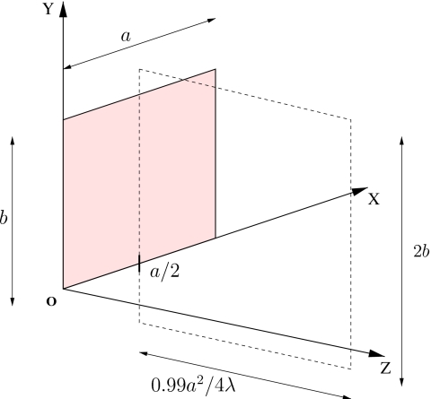
In the derivation that follows, each observation point is denoted by (x,y,z), and each source point is denoted by (μ,ν,0). Figure 1 shows the coordinate system used in the derivation and subsequent evaluations. The rectangular source is located in the z=0 plane, and the origin of the coordinate system O coincides with the lower left corner of the rectangular source. The apodization function of the source is given by f(μ,ν), which is zero outside of the rectangular source. The width of the rectangular source is a and the height is b.
Figure 1.
(Color online) Orientation of the computational grid relative to the rectangular source. The rectangular source, which has width a and height b, lies in the z=0 plane. The dashed lines define the extent of the computational grid in the x=a∕2 plane. The extent of the computational grid is 2b by 0.99a2∕4λ in the y and z directions, respectively.
The FNM expression for a rectangular piston that is excited uniformly is given by McGough.15 A more general unapodized FNM expression for a rectangular piston is obtained from the expression in Ref. 16 for a triangular piston. Here, the FNM expression for the uniformly excited rectangular piston is denoted by p0[μ,ν](x,y,z;k), where the subscript “0” indicates the uniform excitation and μ and ν represent the width and height of the rectangular source, respectively. The near-field pressure for the uniformly excited piston is given by
| (1) |
where ω is the excitation frequency in rad∕s, ρ is the density of the medium, c is the speed of sound, v0 is the constant normal particle velocity evaluated on the surface of the rectangular source, k is the wave number, and σ is an integration variable as defined in Refs. 15, 16. The values of mi and ni, which are functions of μ and ν, represent the upper limits and lower limits of the integral, respectively. In Eq. 1, the values of (mi,ni) are (m1,n1)=(m2,n2)=(μ−x,−x) and (m3,n3)=(m4,n4)=(ν−y,−y), and the values of hi are h1=y, h2=ν−y, h3=x, and h4=μ−x for i=1,2,3,4, respectively. According to Eq. 1, there are two special cases, namely,
| (2) |
where the subelement has zero width or height, respectively. These special cases are utilized in the following derivation of the apodized FNM expression for a rectangular source.
Steady-state apodized FNM expression
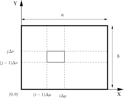
The pressure field papod(x,y,z;k) is obtained by subdividing the rectangular source into N×N small rectangles, where the subscript apod indicates that the pressure is computed with the apodization function f(μ,ν). One of these small rectangles is depicted inside of the rectangular source in Fig. 2. The values Δμ=a∕N and Δν=b∕N denote the width and the height of each small rectangle in the X and Y directions, respectively, and S[i,j] represents the rectangle at the ith column and jth row of the subdivision. The four coordinates of the vertices of S[i,j] are given by ((i−1)Δμ,(j−1)Δμ), (iΔμ,(j−1)Δμ), (iΔμ,jΔμ), and ((i−1)Δμ,jΔμ) for the lower left, lower right, upper right, and upper left coordinates, respectively. The expression p[i,j]=p[iΔμ,jΔν](x,y,z) represents the pressure produced by the uniformly excited rectangular source having width iΔμ and height jΔν, where the lower left corner is located at (0, 0), and the aperture function over the rectangle S[i,j] is defined by q[i,j]=f(iΔμ,jΔν). The total pressure papod(x,y,z;k) is approximated by
| (3) |
According to Eq. 2, p[l,0]=0, and p[0,l]=0, l=1,…,N. By utilizing these restrictions and rearranging Eq. 3,
| (4) |
is obtained. Letting N→∞ such that Δμ→0 and Δν→0, Eq. 4 becomes
| (5) |
where
and
Within these expressions, p0[μ,ν](x,y,z;k) is the single integral from Eq. 1, so papod1(x,y,z;k) is actually a triple integral, papod2(x,y,z;k) and papod3(x,y,z;k) are double integrals that admit further simplification, and papod4(x,y,z;k) is already simplified.
Figure 2.
The decomposition of an apodized rectangular source into smaller rectangles, where each small rectangle is Δμ wide and Δν high. The apodization function f(μ,ν) is defined as constant over each small rectangle.
After substituting the uniformly excited FNM expression p0[μ,ν](x,y,z;k) from Eq. 1, papod1(x,y,z;k) in Eq. 5 becomes
| (6) |
Since the four triple integrals in Eq. 6 all share the same structure, only the derivation of the first integral
| (7) |
is outlined here, where papod1(x,y,z;k)=papod1,i=1(x,y,z;k)+papod1,i=2(x,y,z;k)+papod1,i=3(x,y,z;k)+papod1,i=4(x,y,z;k). Let g1(μ) denote the integral
| (8) |
where h1=y as indicated above. The function g1(μ) is defined in terms of a variable in the upper limit of the integral, so the derivative of g1(μ) with respect to μ is
| (9) |
After integrating by parts with respect to the variable μ, papod1,i=1(x,y,z;k) is rewritten as
| (10) |
According to Eq. 8, g1(0)=0. Substituting the expression for g1(μ) into Eq. 10 and performing an exchange of variables yield the following analytically equivalent expression for the first triple integral:
| (11) |
The other three triple integrals in papod1 are simplified into double integrals using the same strategy.
By substituting p0[μ,b](x,y,z;k) and p0[a,ν](x,y,z;k) from Eq. 1 into papod2(x,y,z;k) and papod3(x,y,z;k) and by using integration by parts, papod2(x,y,z;k) and papod3(x,y,z;k) are converted into the sum of two single integrals and two double integrals, while papod4(x,y,z;k) is already a single integral. After the four terms in Eq. 5 are added and common terms are canceled, the complete FNM expression for an apodized rectangular piston is
| (12) |
where the values of T1i are T11=T12=−∂f(μ,ν)∕∂ν and T13=T14=−∂f(μ,ν)∕∂μ, the values of α1i are α11=α12=μ−x and α13=α14=ν−y, and the values of h1i are h11=y, h12=ν−y, h13=x, and h14=μ−x. The values of T2i are T21=T22=f(σ,b) and T23=T24=f(a,σ), the values of α2i are α21=α22=σ−x and α23=α24=σ−y, the values of h2i are h21=y, h22=b−y, h23=x, and h24=a−x, and the values of (mi,ni) are (m1,n1)=(m2,n2)=(a,0) and (m3,n3)=(m4,n4)=(b,0) for i=1,2,3,4.
The apodized FNM expression in Eq. 12, which contains the summation of four double integrals and four single integrals, describes the pressure generated by an apodized piston for any boundary condition. The apodized FNM expression in Eq. 12 admits further simplification if the apodization function is equal to zero on the piston edge, where
| (13) |
The boundary conditions given by Eq. 13 are equivalent to setting all of the terms T2i equal to 0, so the single integrals with respect to σ in Eq. 12 disappear. The resulting apodized FNM expression is the summation of the four double integrals with respect to μ and ν, so only the first sum in Eq. 12 is needed when the boundary values are all zero.
The FNM expression for the uniformly excited rectangular piston is also a special case of the apodized FNM expression in Eq. 12. For the uniform case, the apodization function is f(μ,ν)=rect(μ∕a)rect(ν∕b) where rect(t)=1 if t∊(0,1) and rect(t)=0 otherwise. The weak derivative of f(μ,ν) is given by ∂f(μ,ν)∕∂μ=δ(μ)−δ(μ−a) and ∂f(μ,ν)∕∂ν=δ(ν)−δ(ν−b). When this apodization function is substituted into Eq. 12, all terms T2i are equal to 0, and the double integrals reduce to a single integral, which is the same as p0[a,b](x,y,z;k) in Eq. 1.
Transient apodized FNM expression
The transient response for an apodized rectangular piston is obtained from the inverse Fourier transform21 of Eq. 12. Defining v(t) as the temporal component of the transient normal particle velocity v(t)f(μ,ν), the transient pressure generated by an apodized rectangular piston is represented by
| (14) |
where the values of T1i, α1i, h1i, T2i, α2i, and h2i are listed immediately after Eq. 12 in the previous section.
The Rayleigh–Sommerfeld integral
The time-harmonic pressure generated by an apodized rectangular source is also computed with the Rayleigh–Sommerfeld integral14 via
| (15) |
where is the distance between the source point (μ,ν,0) and the observation point (x,y,z). The transient pressure generated by an apodized rectangular source with a temporal excitation component v(t) is given by the inverse Fourier transform of Eq. 15, which yields
| (16) |
where is the time derivative of the input excitation pulse v(t). The expressions for the Rayleigh–Sommerfeld integral in Eqs. 15, 16 are analytically equivalent to the apodized FNM expressions in Eqs. 12, 14, but the numerical properties of the two methods differ as demonstrated in the results shown below.
The FIELD II program
The FIELD II program13 is a software package that computes transient and steady-state pressures generated by phased arrays and individual ultrasound transducers. The FIELD II program with the use_rectangles option divides each piston source into small rectangular elements and applies the far-field approximation of the spatial impulse response to each small rectangular element.12FIELD II specifies the apodization at the center point of each small rectangular element. The accuracy of the FIELD II program is dependent on two factors, namely, the sampling frequency and the number of small rectangular elements. With an increase in the sampling frequency or the number of small rectangular elements. FIELD II achieves smaller errors, but the computation time increases accordingly.
Apodization function
The apodization function selected for comparisons between the apodized FNM, the Rayleigh–Sommerfeld integral, and the FIELD II program is the product of sinusoidal functions given by
| (17) |
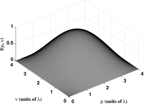
This function corresponds to the lowest order vibration mode of a rectangular membrane with fixed edges.20, 22 Equation 17 is plotted for an apodized rectangular source with each side equal to four wavelengths in Fig. 3.
Figure 3.
The apodization function f(μ,ν)=sin(μπ∕a)sin(νπ∕b) evaluated on the face of a 4λ×4λ square piston. The maximum value of the apodization function is achieved when μ=2λ and ν=2λ.
The apodized FNM equations of Eqs. 12, 14 admit additional simplification when applied to the apodization function in Eq. 17. The apodization function is the product of two sinusoidal functions, so the apodization function is separable with respect to the variables μ and ν. After the derivative of the apodization function with respect to μ and ν is substituted into Eqs. 12, 14, the first and third double integrals contain and terms, respectively. These two integrals are exactly equal to 0, so the first and third double integrals in Eqs. 12, 14 are equal to 0 for the apodization function in Eq. 17 at any observation point. Thus, only the second and fourth double integrals are needed. Furthermore, in Eqs. 12, 14, the second and the fourth double integrals share several terms. Shared terms in the apodized FNM equations are always computed once and stored for use in repeated calculations.
Input transient pulse
For transient calculations, the excitation pulse v(t) is specified by the Hanning-weighted pulse
| (18) |
where rect(t)=1 if t∊(0,1) and rect(t)=0 otherwise. In the transient simulations that follow, the center frequency f0 and the pulse duration W are f0=1.5 MHz and W=2.0 μs, respectively, for the Hanning-weighted pulse.
Time space decomposition
For transient calculations, most of the computation time is expended while evaluating v(t−τ) in Eq. 14 and in Eq. 16. These terms are calculated at each time t. The variable τ is a function of the observation coordinates only, so τ represents the contribution from the spatial variable. The function v(t−τ) can be separated according to the time space decomposition approach in Ref. 21. This expression is decoupled as
| (19) |
where M=6 for transient FNM calculations with the Hanning-weighted pulse in Eq. 18, W is the length of the pulse, and the fm(τ) and gm(t) terms are given in Table 1. The transient input to Eq. 16 is decoupled in the same manner, and the corresponding fm(τ) and gm(t) terms for are given in Table 2 where M=10 for transient Rayleigh–Sommerfeld calculations with the Hanning-weighted pulse. A simplified version of the time space decomposition algorithm is outlined below.
-
(1)
Precompute and store gm(t) in advance for all values of t.
-
(2)
Evaluate τ once for each spatial coordinate.
-
(3)
Compute the values of each fm(τ) term immediately after τ is calculated.
-
(4)
Calculate the value of v(t−τ) according to Eq. 19.
By exploiting repeated calculations, this approach dramatically reduces the computation time without increasing the numerical error.
Table 1.
Terms that define the time space decomposition of the Hanning-weighted pulse v(t−τ) for transient apodized FNM calculations.
| Temporal basis functions gm(t) | |
|---|---|
| Spatial basis functions fm(τ) | |
| f1(τ)=cos(2πf0τ) | |
| f2(τ)=sin(2πf0τ) | |
Table 2.
Terms that define the time space decomposition of the derivative of a Hanning-weighted pulse for transient calculations with the apodized Rayleigh–Sommerfeld integral.
| Temporal basis functions gm(t) | |
|---|---|
| g1(t)=πf0 cos(2πf0t) | |
| g2(t)=πf0 sin(2πf0t) | |
| Spatial basis functions fm(τ) | |
| f1(τ)=cos(2πf0τ) | |
| f2(τ)=sin(2πf0τ) | |
Error calculations
Two error metrics are used in this paper: one is the normalized error distribution η(x,y,z;k), which describes the absolute value of the pressure difference at each spatial point for time-harmonic calculations; and the other is the normalized root mean square error (NRMSE), which describes the overall error performance with a single value. Let p(x,y,z;k) represent the computed pressure field, and let pref(x,y,z;k) represent the reference pressure field. The normalized error distribution η(x,y,z;k) for each spatial point in time-harmonic calculations is given by
| (20) |
The value of η(x,y,z;k) is shown in each depiction of the error mesh. The NRMSE across all spatial points for time-harmonic calculations is
| (21) |
where ∑x,y,z denotes summation over all of the spatial grid points. The NRMSE for transient calculations is
| (22) |
where ∑x,y,z,t denotes summation over all spatial and temporal grid points. The values of the NRMSE are tabulated for each method in the Results section. The reference fields pref(x,y,z;k) and pref(x,y,z;t) for time-harmonic calculations and transient calculations, respectively, are calculated using the Rayleigh–Sommerfeld integral.
For near-field pressure calculations with the apodized FNM expressions and the Rayleigh–Sommerfeld integral, the numbers of abscissas in the μ and ν directions are the same for a square source. The NRMSE values for both methods are computed as the number of abscissas ranges from 2 to 100. The number of abscissas for a given NRMSE is determined by the smallest number of abscissas that has a NRMSE smaller than the desired NRMSE value. For near-field pressure calculations with the FIELD II program, the sampling frequency fs and the number of small rectangular elements are the two factors that determine the value of the NRMSE. The sampling frequency is varied from 16 to 160 MHz with a step size of 16 MHz, and the number of small rectangular elements in each direction ranges from 10 to 60 with a step size of 5. The NRMSE for each combination of the sampling frequency and the number of small rectangular elements is then computed. The sampling frequency and the number of small rectangular elements for a given NRMSE are determined by the combination that has the smallest computation time.
Computational resources
The simulations are performed on a Dell Precision 360 personal computer with a 2.80 GHz Pentium 4 processor. The operating system is Windows XP professional. All simulation programs are written in the C language and run sequentially. The apodized FNM expression and the Rayleigh integral are both evaluated using Gauss quadrature.
RESULTS
Time-harmonic pressure calculations
Reference pressure field
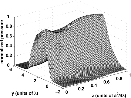
The reference pressure field in Fig. 4 is computed for the apodization function shown in Fig. 3. In Fig. 4, the acoustic field is evaluated in the x=2.0λ plane, where the grid in the x=2.0λ plane extends from −2λ to 6λ in the y direction, and the grid spacing in the y direction is 0.1λ. The grid extends from 0.01a2∕4λ to 1.0a2∕4λ in the z direction with a spacing of 0.01a2∕4λ. The computational grid in the z direction is shifted by 0.01a2∕4λ relative to the source in the z=0 plane for all three methods in order to avoid the most severe singularities in this location. Although the apodized FNM eliminates the worst singularities in the z=0 plane, the grid is nevertheless shifted slightly to reduce the problems that the Rayleigh integral and the FIELD II program encounter on the piston face. The reference pressure field shown in Fig. 4 is obtained using the Rayleigh–Sommerfeld integral evaluated with 100 000 Gauss abscissas in each direction, and the results are computed on an 81×100 spatial grid.
Figure 4.
Simulated reference pressure field generated by an apodized rectangular source with each side equal to four wavelengths. The results are evaluated in the x=2.0λ plane for a time-harmonic excitation.
Error distributions
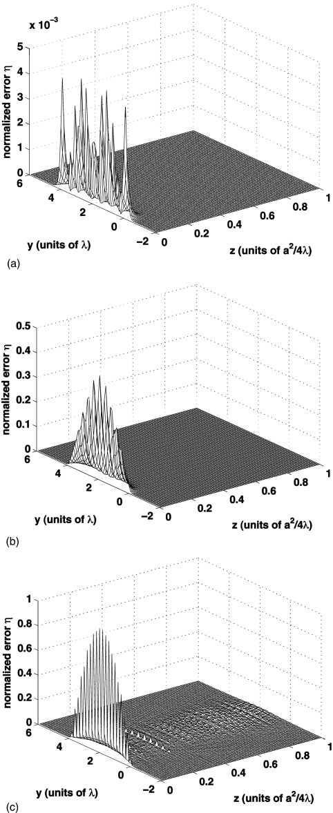
Figure 5 shows the normalized error distribution η(x,y,z;k) between the reference pressure field in Fig. 4 and the simulated pressure field computed using the apodized FNM expression, the apodized Rayleigh–Sommerfeld integral, and the FIELD II program, where each is evaluated with the apodization function specified by Eq. 17. The region near the piston face contains the largest errors for all three methods. The NRMSE for the apodized FNM evaluated with N=16 Gauss abscissas in each direction is 0.0005. The apodized Rayleigh–Sommerfeld integral evaluated with N=16 Gauss abscissas in each direction has a NRMSE of 0.0450. The FIELD II program computed with a 48 MHz sampling frequency and 30 subdivisions in each direction achieves a NRMSE of 0.0808.
Figure 5.
The normalized error distribution η(x,y,z;k) describes the difference between the reference pressure field and the computed pressure field for an apodized 4λ×4λ source. The error distribution η is plotted for (a) the apodized FNM evaluated with 16-point Gauss quadrature in each direction, (b) the apodized Rayleigh integral evaluated with 16-point Gauss quadrature in each direction, and (c) the FIELD II program evaluated with fs=48 MHz and 30 subdivisions in each direction.
Time versus error comparisons for a time-harmonic input
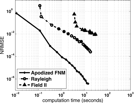
Figure 6 shows the computation times and the error values for near-field pressure calculations with a time-harmonic input applied to the apodized FNM, the Rayleigh–Sommerfeld integral, and the FIELD II program. In Fig. 6, the apodized FNM achieves the smallest errors for a given computation time, and the apodized FNM uses the least amount of time for a given error value. Comparisons between the apodized FNM, the Rayleigh integral, and the FIELD II program are summarized in Table 3. To achieve a NRMSE of 0.1, the apodized FNM needs six abscissas in each direction, and the computation time is 0.07 s. The apodized FNM achieves a NRMSE of 0.01 in 0.18 s with ten abscissas in each direction. Likewise, to achieve a NRMSE of 0.1, the Rayleigh–Sommerfeld integral needs 12 abscissas in each direction, and the computation time is 0.29 s. The Rayleigh–Sommerfeld integral achieves a NRMSE of 0.01 in 2.25 s with 34 abscissas in each direction. Instead of evaluating an integral with a certain number of abscissas, the FIELD II program subdivides the aperture into small rectangular sources and calculates the impulse response at a specified sampling frequency. To achieve a NRMSE of 0.1, the FIELD II program requires a temporal sampling frequency of 64 MHz and 20 subdivisions in each direction, and the result is obtained in 4.61 s. The FIELD II program achieves a NRMSE of 0.01 with a temporal sampling frequency of 160 MHz and 50 subdivisions in each direction. This calculation is completed in 27.91 s. Thus, for a NRMSE of 0.1, the apodized FNM is 4.14 times faster than the Rayleigh integral, and the apodized FNM is 59.43 times faster than the FIELD II program. For a NRMSE of 0.01, the apodized FNM is 12.50 times faster than the Rayleigh integral and the apodized FNM is 155.06 times faster than the FIELD II program. These results are specific to the grid and piston geometry in Fig. 3 and the apodization function in Eq. 17. Although the results vary somewhat for different parameter combinations, the apodized FNM consistently achieves the best performance in time versus error comparisons. The apodized FNM is also an ideal reference for time-harmonic calculations due to the rapid convergence of Eq. 12.
Figure 6.
Normalized root mean square error (NRMSE) plotted as a function of the computation time for time-harmonic calculations with the apodized FNM, the apodized Rayleigh–Sommerfeld integral, and the FIELD II program. This figure demonstrates that the apodized FNM achieves the smallest errors for a given computation time and that the apodized FNM requires the smallest amount of time to achieve a given error value.
Table 3.
Simulation parameters for time-harmonic calculations that achieve normalized root mean square error (NRMSE) values of 0.1 and 0.01. The parameters listed include the number of Gauss abscissas or the corresponding FIELD II parameters, the resulting computation time, and the ratio of the computation time relative to the apodized FNM for the Rayleigh integral and the FIELD II program.
| Time-harmonic calculations | ||||||
|---|---|---|---|---|---|---|
| 0.1 NRMSE | 0.01 NRMSE | |||||
| Apodized FNM | Rayleigh | FIELD II | Apodized FNM | Rayleigh | FIELD II | |
| Simulationparameters | 6×6 abscissas | 12×12 abscissas | fs=64 MHz20×20 subdivisions | 10×10 abscissas | 34×34 abscissas | fs=160 MHz50×50 subdivisions |
| Time (s) | 0.07 | 0.29 | 4.61 | 0.18 | 2.25 | 27.91 |
| Computation timerelative toapodized FNM | 1× | 4.14× | 59.43× | 1× | 12.50× | 155.06× |
Transient field calculations
Reference pressure field
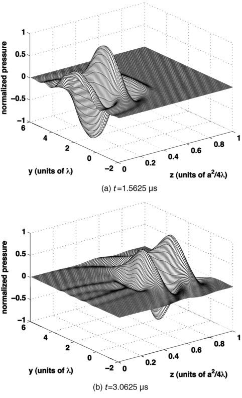
The reference transient field is computed using the transient Rayleigh–Sommerfeld integral in Eq. 16, where the numerical integration is performed with 100 000 Gauss abscissas applied in both the height and width directions. The input pulse is the Hanning-weighted pulse in Eq. 18 with center frequency f0=1.5 MHz and pulse length W=2.0 μs. The speed of sound is c=1.5 mm∕μs, and the wavelength at the center frequency is λ=1.0 mm. The sampling frequency is 16 MHz. The transient field is evaluated in the x=2.0λ plane, where the computational grid extends from −2λ to 6λ in the y direction and from 0.01a2∕4λ to 1.0a2∕4λ in the z direction, as shown in Fig. 1. The reference transient field is calculated on an 81×100 spatial grid evaluated at 192 time points. Figure 7 shows two transient plots of the reference pressure evaluated at times t=1.5625 μs and t=3.0625 μs.
Figure 7.
Simulated reference transient field for an apodized square source excited by the Hanning-weighted pulse in Eq. 18 with f0=1.5 MHz and W=2.0λ. The sides of the square source are equal to 4λ, where the wavelength is defined with respect to the center frequency f0. The apodization function is given by Eq. 17. The transient reference pressure, evaluated in the x=2.0λ plane, is computed with 100 000 Gauss abscissas in each direction using the Rayleigh integral. The results are plotted at (a) t=1.5625 μs and (b) t=3.0625 μs.
Time versus error comparisons for a Hanning-weighted input pulse
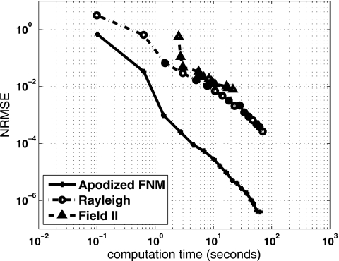
Figure 8 shows the computation times and the numerical errors for the transient pressure field generated by the Hanning-weighted input pulse evaluated with the transient apodized FNM, the transient Rayleigh–Sommerfeld integral, and the FIELD II program. For both the transient apodized FNM and the transient Rayleigh–Sommerfeld integral, the simplified time space decomposition approach is applied as described in Sec. 2G. In Fig. 8, the transient apodized FNM achieves the smallest errors for a given computation time, and the transient apodized FNM requires the smallest amount of time to achieve a given error. Comparisons between the transient apodized FNM, the transient Rayleigh integral, and the FIELD II program are summarized in Table 4. To achieve a NRMSE of 0.1 with the Hanning-weighted pulse, the transient apodized FNM needs eight abscissas in each direction and the computation time is 0.64 s. The transient apodized FNM achieves a NRMSE of 0.01 in 0.72 s with ten abscissas applied in each direction. To achieve a NRMSE of 0.1 with the Hanning-weighted pulse, the transient Rayleigh–Sommerfeld integral needs 14 abscissas in each direction and the computation time is 1.48 s. The transient Rayleigh–Sommerfeld integral achieves a NRMSE of 0.01 in 8.57 s with 34 abscissas in each direction. To achieve a NRMSE of 0.1 with the Hanning-weighted pulse, the FIELD II program requires a temporal sampling frequency of 64 MHz and 20 subdivisions in each source direction, and the result is obtained in 4.68 s. The FIELD II program achieves a NRMSE of 0.01 with a temporal sampling frequency of 128 MHz and 50 subdivisions in each source direction. This calculation is completed in 24.04 s. Thus, for a NRMSE of 0.1, the transient apodized FNM is 2.31 times faster than the transient Rayleigh integral and the transient apodized FNM is 4.66 times faster than the FIELD II program. For a NRMSE of 0.01, the transient apodized FNM is 11.90 times faster than the transient Rayleigh integral and the transient apodized FNM is 24.04 times faster than the FIELD II program. Once again, these results are specific to the grid, apodization function, and piston geometry utilized in this paper. Overall, the transient apodized FNM achieves the best performance in time versus error comparisons with the Hanning-weighted pulse.
Figure 8.
Normalized root mean square error (NRMSE) plotted as a function of the computation time for transient pressure calculations evaluated with the apodized FNM, the apodized Rayleigh–Sommerfeld integral, and the FIELD II program. For the same computation time, the apodized FNM achieves the smallest errors. For the same error, the apodized FNM requires the least amount of time.
Table 4.
Simulation parameters for transient calculations that achieve normalized root mean square error (NRMSE) values of 0.1 and 0.01. The parameters listed include the number of Gauss abscissas or the corresponding FIELD II parameters, the resulting computation time, and the ratio of the computation time relative to the apodized FNM for the Rayleigh integral and the FIELD II program.
| Transient calculations | ||||||
|---|---|---|---|---|---|---|
| 0.1 NRMSE | 0.01 NRMSE | |||||
| Apodized FNM | Rayleigh | FIELD II | Apodized FNM | Rayleigh | FIELD II | |
| Simulationparameters | 8×8 abscissas | 14×14 abscissas | fs=64 MHz20×20 subdivisions | 10×10 abscissas | 34×34 abscissas | fs=128 MHz50×50 subdivisions |
| Time (s) | 0.64 | 1.48 | 2.98 | 0.72 | 8.57 | 17.26 |
| Computation timerelative toapodized FNM | 1× | 2.31× | 4.66× | 1× | 11.90× | 24.04× |
DISCUSSION
Large-scale computation
Despite the dramatic increase in processor speeds and computer memory in recent decades, near-field pressure calculations that numerically evaluate the Rayleigh–Sommerfeld integral are still very slow. This is especially evident in calculations performed on large grids, which take an hour or more on the fastest modern desktop computers. For example, more than 1 h was needed in a recent paper to compute the reference pressure field in the Fresnel zone for a single element using the Rayleigh–Sommerfeld approach.20 More recently, near-field pressure calculations with the Rayleigh–Sommerfeld approach for a single element required 117 h per simulation to achieve a NRMSE of 10−7. Thus, even for simulations of single elements performed in the near-field region, traditional computational methods perform poorly, and faster methods such as the FNM are needed.
Computation times with the Rayleigh–Sommerfeld integral can also be excessively long for phased array simulations. Extending the results shown in Tables 3, 4 and Figs. 68 to a linear phased array with 1024 rectangular elements evaluated on a computational grid with 100×100×100 points in the x, y, and z directions, the Rayleigh–Sommerfeld integral will require about 10 h for a 0.1 NRMSE and about 80 h for a 0.01 NRMSE. For the same array evaluated on the same grid, the FNM will require only 2.5 h for a 0.1 NRMSE and 6.5 h for a 0.01 NRMSE. Thus, for large-scale computations, the time savings achieved by the apodized FNM is substantial. The apodized FNM is also an ideal reference for both time-harmonic and transient calculations.
Time and error comparisons
In addition to the results presented in Tables 3, 4 and Figs. 68 that compare the Rayleigh–Sommerfeld integral and the apodized FNM, the individual computation times and error values were also determined as a function of the number of abscissas. Those results show that, for a given number of abscissas, the apodized FNM achieves much smaller errors than the Rayleigh–Sommerfeld integral, and the computation time of the apodized FNM is slightly less than that of the Rayleigh integral for the same number of abscissas. Therefore, the rapid convergence of the apodized FNM is responsible for the enhancement in performance relative to other methods. However, fair comparisons of these methods require the evaluation of both times and errors, as shown in Tables 3, 4 and Figs. 68. Otherwise, a method that generates large errors in a similar amount of time or a method that requires much more time to achieve a similar error could be incorrectly identified as having comparable performance. Thus, the method with superior performance should consistently achieve the smallest error in the shortest time.
Apodization functions
Equations 12, 14 can be applied to a large class of apodization functions. The only requirement for the apodization functions is that ∂f(μ,ν)∕∂μ and ∂f(μ,ν)∕∂ν exist. Other approaches have different requirements. For example, Fresnel approximations have been obtained for several apodization functions including exponential, sinusoidal, Gaussian, or error-function apodization functions.20 One restriction for these Fresnel approximations is that the surface velocity distribution should be separable such that f(μ,ν)=fx(μ)fy(ν). The advantages of the apodized FNM expressions in Eqs. 12, 14 are that (1) separability of the apodization function is not required and (2) accurate results are obtained very close to the piston face.
Pressures generated by a Gaussian apodization function,23, 24, 25 given by where μ0, ν0, σμ, and σν are constants, were also evaluated with Eq. 12. When the Gaussian apodization function is applied, the entire expressions in Eqs. 12, 14 are needed because the T2i terms are nonzero in this case. Furthermore, the integration limits of the single integrals are either (0,a) or (0,b), so the abscissas and weights computed for the single integrals can also be used for the double integrals. The computation time needed for all terms in Eqs. 12, 14 is only slightly more than that needed to evaluate only the double integrals, especially when the number of abscissas is larger than ten in one direction.
Time space decomposition
The expressions for the transient near-field pressures are computed with the simplified time space decomposition approach outlined in Sec. 2G for both the transient apodized FNM expression and the transient Rayleigh–Sommerfeld integral in Eqs. 14, 16, respectively. The simplified time space decomposition approach provides an important advantage in that, unlike the original time space decomposition method described by Kelly and McGough,18 both one-dimensional (1D) and 2D near-field diffraction integrals are readily computed. The original time space decomposition method of Kelly and McGough18 stores a three-dimensional (3D) K matrix that captures the arrival and departure information for a finite duration pulse, where the transient pressure propagation is described by a single integral FNM expression. Extending the original time space decomposition to handle transient calculations with the 2D apodized FNM expressions in Eq. 14 or the Rayleigh–Sommerfeld integral in Eq. 16 involves replacing the 3D K matrix with a complicated five-dimensional K matrix. With the simplified time space decomposition approach, no matrix storage is needed. Thus, the algorithm complexity and the memory usage are greatly reduced. The simplified time space decomposition in Sec. 2G is preferred for transient calculations with 2D integrals, where a significant reduction in the computation time is achieved relative to other approaches without increasing the numerical error. For transient calculations with 1D integrals, there is a trade-off between the simplified time space decomposition and the original time space decomposition method. The original time space decomposition requires more memory, is more complicated to program, and is slightly faster, while the simplified time space decomposition is much easier to program.
CONCLUSION
A 2D FNM for calculating the near-field pressure generated by an apodized rectangular piston is derived and evaluated, and a simplified time space decomposition technique is outlined for transient apodized FNM and transient apodized Rayleigh–Sommerfeld calculations. Comparisons between the apodized FNM, the Rayleigh–Sommerfeld integral, and the FIELD II program show that the apodized FNM achieves the smallest error in the shortest time for both steady-state and transient calculations. For time-harmonic calculations with a NRMSE of 0.01, the apodized FNM is 4.14 times faster than the Rayleigh–Sommerfeld integral and 59.43 times faster than the FIELD II program. For a NRMSE of 0.01, the time-harmonic apodized FNM is 12.50 times faster than the Rayleigh–Sommerfeld integral and 155.06 times faster than the FIELD II program. For transient calculations with a NRMSE of 0.1, the apodized FNM is 2.31 times faster than the Rayleigh–Sommerfeld integral and 4.66 times faster than the FIELD II program. For a NRMSE of 0.01, the transient apodized FNM is 11.90 times faster than the Rayleigh–Sommerfeld integral and 24.04 times faster than the FIELD II program. In addition, the apodized FNM converges much faster than the Rayleigh–Sommerfeld integral and the FIELD II program. Thus, the apodized FNM is ideal for fast near field pressure calculations and also for accurate reference calculations.
ACKNOWLEDGMENTS
The authors would like to thank James F. Kelly and Xiaozheng Zeng for thoughtful discussions. This work was supported in part by NIH R01 CA093669, NIH R21 CA121235, NSF 0634786, and NIH P01 CA042745.
References
- Harris G. R., “Review of transient field theory for a baffled planar piston,” J. Acoust. Soc. Am. 10.1121/1.386687 70, 10–20 (1981). [DOI] [Google Scholar]
- Greenspan M., “Piston radiator: Some extensions of the theory,” J. Acoust. Soc. Am. 10.1121/1.382496 65, 608–621 (1979). [DOI] [Google Scholar]
- Lafon C., Prat F., Chapelon J. Y., Gorry F., Margonari J., Theillere Y., and Cathignol D., “Cylindrical thermal coagulation necrosis using an interstitial applicator with a plane ultrasonic transducer: In vitro and in vivo experiments versus computer simulations,” Int. J. Hyperthermia 10.1080/02656730050199359 16, 508–522 (2000). [DOI] [PubMed] [Google Scholar]
- Daum D. R. and Hynynen K., “A 256-element ultrasonic phased array system for the treatment of large volumes of deep seated tissues,” IEEE Trans. Ultrason. Ferroelectr. Freq. Control 10.1109/58.796130 46, 1254–1268 (1999). [DOI] [PubMed] [Google Scholar]
- Li Y. and Zagzebski J. A., “A frequency domain model for generating B-mode images with array transducers,” IEEE Trans. Ultrason. Ferroelectr. Freq. Control 10.1109/58.764855 46, 690–699 (1999). [DOI] [PubMed] [Google Scholar]
- Cincotti G., Cardone G., Gori P., and Pappalardo M., “Efficient transmit beamforming in pulse-echo ultrasonic imaging,” IEEE Trans. Ultrason. Ferroelectr. Freq. Control 46, 1450–1458 (1999). [DOI] [PubMed] [Google Scholar]
- Lin Y., Dodson J. M., Hamilton J. D., Kluiwstra J.-U. A., Cain C., and Grosh K., “Theory and experiment for the design of piezoeletric element for phased arrays,” Proc.-IEEE Ultrason. Symp. 2, 1697–1700 (1997). [Google Scholar]
- Prego Borges J. L., Montero de Espinosa F., Salazar J., Garcia-Alvarez J., Chavez J. A., Turo A., and Garcia-Hernandez M. J., “Diffraction aperture non-ideal behaviour of air coupled transducers array elements designed for NDT,” Ultrasonics 44, 667(E)–672(E) (2006). [DOI] [PubMed] [Google Scholar]
- Stepanishen P. R., “Transient radiation from pistons in an infinite planar baffle,” J. Acoust. Soc. Am. 10.1121/1.1912541 49, 1629–1638 (1971). [DOI] [Google Scholar]
- Oberhettinger F., “On transient solutions of the ‘baffled piston’ problem,” J. Res. Natl. Bur. Stand., Sect. B 65B, 1–6 (1961). [Google Scholar]
- Lockwood J. C. and Willette J. G., “High-speed method for computing the exact solution for the pressure variations in the nearfield of a baffled piston,” J. Acoust. Soc. Am. 10.1121/1.1913385 53, 735–741 (1973). [DOI] [Google Scholar]
- Jensen J. A. and Svendsen N. B., “Calculation of pressure fields from arbitrarily shaped, apodized, and excited ultrasound transducers,” IEEE Trans. Ultrason. Ferroelectr. Freq. Control 10.1109/58.139123 39, 262–267 (1992). [DOI] [PubMed] [Google Scholar]
- Jensen J. A., “Field: A program for simulating ultrasound systems,” Med. Biol. Eng. Comput. 10.1007/BF02520003 34, 351–353 (1996). [DOI] [PubMed] [Google Scholar]
- Ocheltree K. B. and Frizzell L. A., “Sound field calculation for rectangular sources,” IEEE Trans. Ultrason. Ferroelectr. Freq. Control 10.1109/58.19157 36, 242–248 (1989). [DOI] [PubMed] [Google Scholar]
- McGough R. J., “Rapid calculations of time-harmonic nearfield pressures produced by rectangular pistons,” J. Acoust. Soc. Am. 10.1121/1.1694991 115, 1934–1941 (2004). [DOI] [PMC free article] [PubMed] [Google Scholar]
- Chen D., Kelly J. F., and McGough R. J., “A fast nearfield method for calculations of time-harmonic and transient pressures produced by triangular pistons,” J. Acoust. Soc. Am. 120, 2450–2459 (2006). [DOI] [PMC free article] [PubMed] [Google Scholar]
- McGough R. J., Samulski T. V., and Kelly J. F., “An efficient grid sectoring method for calculations of the nearfield pressure generated by a circular piston,” J. Acoust. Soc. Am. 10.1121/1.1687835 115, 1942–1954 (2004). [DOI] [PMC free article] [PubMed] [Google Scholar]
- Kelly J. F. and McGough R. J., “A fast time-domain method for calculating the nearfield pressure generated by a pulsed circular piston,” IEEE Trans. Ultrason. Ferroelectr. Freq. Control 10.1109/TUFFC.2006.1642513 53, 1150–1159 (2006). [DOI] [PMC free article] [PubMed] [Google Scholar]
- Zeng X. and McGough R. J., “Evaluation of the angular spectrum approach for simulations of nearfield pressures,” J. Acoust. Soc. Am. 10.1121/1.2812579 123, 68–76 (2008). [DOI] [PMC free article] [PubMed] [Google Scholar]
- Mast T. D., “Fresnel approximations for acoustic fields of rectangularly symmetric sources,” J. Acoust. Soc. Am. 10.1121/1.2726252 121, 3311–3322 (2007). [DOI] [PubMed] [Google Scholar]
- Kelly J. F. and McGough R. J., “An annular superposition integral for axisymmetric radiators,” J. Acoust. Soc. Am. 10.1121/1.2405124 121, 759–765 (2007). [DOI] [PMC free article] [PubMed] [Google Scholar]
- Szabo T. L., “Generalized fourier transform diffraction theory for parabolically anisotropic media,” J. Acoust. Soc. Am. 10.1121/1.381690 63, 28–34 (1978). [DOI] [Google Scholar]
- Wen J. J. and Breazeale M. A., “A diffraction beam field expressed as the superposition of Gaussian beams,” J. Acoust. Soc. Am. 10.1121/1.396508 83, 1752–1756 (1988). [DOI] [Google Scholar]
- Ding D., Zhang Y., and Liu J., “Some extensions of the Gauss beam expansion: Radiation fields of the rectangular and the elliptical transducer,” J. Acoust. Soc. Am. 10.1121/1.1572144 113, 3043–3048 (2003). [DOI] [PubMed] [Google Scholar]
- Cook B. D. and W. J.ArnoultIII, “Gaussian-Laguerre/Hermite formula for the nearfield of an ultrasonic transducer,” J. Acoust. Soc. Am. 10.1121/1.380832 59, 9–11 (1976). [DOI] [Google Scholar]


