Abstract
The original spiral tube support (STS) assembly is improved by changing the shape of the tubing, with 1-cm presses perpendicularly along the length. This modification interrupts the laminar flow of the mobile phase. The tubing in the 4 return grooves to the center of the rotor is flattened by a specially made pressing tool to decrease the dead volume and thus increase the column efficiency. The performance of this spiral tube assembly was tested in separations of dipeptides and proteins with suitable polar two-phase solvent systems. The results revealed that the present system yields high partition efficiency with a satisfactory level of stationary phase retention in a short elution time. The present high-speed counter-current chromatographic system will be efficiently applied to a broad spectrum of two-phase solvent systems including aqueous-aqueous polymer phase systems which are used for separation of biopolymers such as proteins and nucleic acids. .
Keywords: spiral tube support assembly, high-speed counter-current chromatography, Separation of proteins and peptides, polymer phase system (TPAS)
1. Introduction
The conventional multilayer coil separation column for high-speed counter-current chromatography (HSCCC) has been widely used for the separation of natural products [1]. The separation of extremely polar compounds, however, becomes a problem due to the low retention of their solvent systems. In order to solve this problem, a spiral disk assembly has been introduced [2]. It consisted of several inert plastic discs each having a single or 4 spiral grooves to facilitate retention of the stationary phase by the radial centrifugal force acting along its spiral pitch which holds the heavier phase on the outer portion and the lighter phase in the inner portion of each spiral channel. It was found that the system can efficiently separate dipeptides and other peptides with polar butanol solvent systems, but it failed to produce efficient separation for proteins with polymer phase systems [3] despite the satisfactory retention of the stationary phase. The spiral disk has been further improved by segmenting the spiral channel with barricades and introducing a glass bead in every other segment [4, 5]. This mixer-settler HSCCC gives a highly efficient protein separation at several hundred theoretical plates, but the application of this system is limited to the separation of macromolecules with aqueous-aqueous polymer phase systems.
To improve the system, we have made a spiral tube support which is a frame that accommodates a single long PTFE tubing into four interweaved spirals in multiple layers. Each spiral groove is interconnected with a radial groove which joins the outer terminal of the spiral groove to the inner terminal of the next spiral at the center. This STS assembly has been successfully used for separation of dipeptides with a polar butanol solvent system [6]. However, the system gives low efficiency in protein separation, as expected from the studies on the original spiral disk assembly. The present paper describes an improved spiral tube assembly which provides efficient separation of proteins and peptides by modifying the tubing configuration forming intermittent compressions which interrupt laminar flow of the mobile phase.
2. Experimental
2.1. Design of the separation column
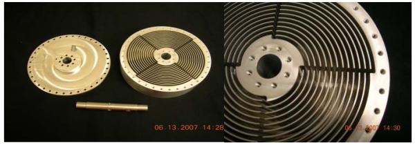
The apparatus used in the present study is a J-type coil planet centrifuge manufactured by P.C. Inc, Potomac, MD, USA. It holds a separation column on one side and a counterweight on the other side of the rotor symmetrically at 10 cm from the central axis of the apparatus. The original STS illustrated in Fig. 1 is designed in our laboratory and fabricated in the National Institutes of Health Machine Instrumentation Facility. The STS is made from an aluminum disk with channels, 5 cm deep and 3 mm in width forming the 4 interweaved spirals. In order to pass the transfer tube, four radial grooves were made as shown in the photograph. The sharp turn at each end of the radial grooves was rounded to prevent kinking of the tubing. The column is made by inserting a single piece of fluorinated plastic tubing of 1.6 mm or 1.35 mm I.D. (PTFE and FEP No.14 or PTFE No.16, Zeus Industrial Products, Orangeburg, SC, USA) into the grooves making the spiral layers. The present design of the STS requires placing a set of four transfer tubes in radial grooves between the neighboring spiral tube layers, taking up space thus limiting the column capacity. In order to increase the column capacity, the tubing in the four radial grooves are pressed down with a metal or hard tool that fits into two or all four of the grooves. This process increases the spiral tube layers that can fit in the spiral tube support frame from 9 to 13 layers, thus increasing the total column capacity from 100 ml to 130 ml for 1.6 mm I.D. tubing. Additionally, the partition efficiency for protein separation was further improved by pressing the tubing with a pair of pliers perpendicularly at every 1 cm to prevent laminar flow formation which substantially reduces partition efficiency of the polymer phase systems for macromolecules such as proteins and nucleic acids.
Fig. 1.
Photograph of the spiral tube support
Each terminal of the spiral tube assembly is connected to 0.85 mm I.D. PTFE flow tubing which is passed through the hollow column holder shaft and then the central shaft of the apparatus to exit the centrifuge. These tubes are tightly supported with a pair of clamps on the top of the centrifuge cover. In this type-J coil planet centrifuge, the flow tubes are not twisted in the revolution so that continuous elution is performed without rotary seals with the accompanying risk of leakage and contamination. The revolution rate of the apparatus is regulated up to 1200 rpm with a speed controller (Bodine Electric, Chicago, IL, USA). A metering pump (Waters 510 HPLC pump, Waters, Milford, MA, USA) was used for pumping the solvents, and the effluent was continuously monitored with a UV detector (LKB Instruments, Stockholm, Sweden). A dialysis cartridge (MicroKros 22 cm, Spectrum, New Brunswick, NJ, USA) inserted at the inlet of the UV monitor to mix the effluent with a suitable solvent (water for the polymer phase system and ethanol for the butanol solvent system) at a 5 : 1 ratio was found to reduce the noise in the chromatogram tracing by dissolving the phase droplets.
2.2. Reagents
HPLC grade 1-butanol was purchased from Fisher Scientific (Park Lawn, NJ. USA). Other solvents such as glacial acetic acid and ethanol were obtained from Mallinckrodt Baker, Inc., Phillipsburg, NJ, USA. Other reagents including PEG (polyethylene glycol)1000, dibasic potassium phosphate, tryptophyl tyrosine (Trp-Tyr), valyl-tyrosine (Val-Tyr), lysozyme (chicken egg) and myoglobin (horse skeletal muscle) were purchased from Sigma, St. Louis, MO, USA.
2.3. Preparation of two-phase solvent systems and sample solutions
Two sets of two-phase solvent systems were prepared: 1-butanol-acetic acid-water (4:1:5, v/v/v) for the separation of dipeptides, and 12.5% (w/w) PEG 1000 and 12.5% (w/w) dibasic potassium phosphate in water for the separation of protein samples. Each solvent system was prepared by mixing the solvents in a separatory funnel by shaking several times and degassing by connecting the outlet of the inversed funnel to a vacuum line for a few seconds two or three times. Sample solutions were prepared as follows: for protein samples, a stock solution was made by dissolving 100 mg each of lysozyme and myoglobin in 20 ml of the upper phase of the solvent system used for separation. After mixing with a vortex mixer, several times, the sample solution was filtered through a membrane (Durapore 0.22 μm membrane, Millipore, Bedford, MA, USA). After filtration, a small amount of lower phase was added to the solution until it showed a cloudy appearance (this indicates two-phase formation that ensures two phase formation with the mobile phase in the column). For each separation, 1 ml (containing 5 mg of each protein) was charged into the sample loop. For dipeptide separation, the stock solution was made by dissolving 25 mg of Trp-Tyr and 100 mg of Val-Tyr in 20 ml of the upper phase of the solvent system used for separation. After dissolving the sample, a small amount of the lower phase was added until the solution became cloudy ensuring the two-phase formation as explained above. In each separation 1 ml of the stock solution (containing 1.25 mg of Typ-Tyr and 5 mg of Val-Tyr) was charged through the sample loop.
2.4. Separation procedure
In each separation, the spiral column was first filled with the stationary phase, either upper or lower phase of a mutually saturated solvent system, followed by sample injection through a l ml-capacity sample loop. Then the apparatus was rotated at a desired rate while the mobile phase is pumped into the inlet of the column at a given flow rate. Out of 8 possible elution modes, a set of four elution modes was examined: lower mobile phase pumped into the internal tail terminal of the spiral (L-I-T); lower mobile phase pumped into the internal head terminal (L-I-H); upper mobile phase pumped into the external tail terminal (U-O-T); and upper mobile phase pumped into the external head terminal (U-O-H). Other 4 elution modes, introducing the lower phase from the external terminal or upper phase from the internal terminal that would give low level of stationary phase retention were eliminated from the present study.
2.5. Computation of partition efficiency
In each separation, partition efficiency in terms of theoretical plate number (N or TP) and peak resolution (RS) was computed from the chromatogram according to the conventional equations:
| (1) |
| (2) |
where R denotes the retention volume and W, the peak width in general (1) or for specified components (2).
The retention of the stationary phase (SF) was estimated from the position of the solvent front or the distance between two peaks (ΔR) using the following equation
| (3) |
where K1 and K2 are the partition coefficient (solute concentration in the stationary phase divided by that in the mobile phase) of two components (K1>K2).
3. Results and discussion
3.1. Design of the spiral tube support
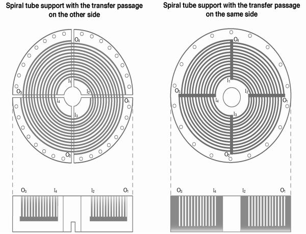
The spiral tube assembly is made solely from a single piece of tubing wound into multiple spiral layers without any joining of segments. There are two ways to make a tube support for this purpose as shown in Fig. 2. The left diagram shows a disk with four interweaved deep spiral grooves. It has an open slot at each spiral terminal through which the tubing can go to the other side. Tube winding is started at the internal terminal of one spiral groove ending at the external terminal which is 90 degrees past the starting point. Then the tubing goes through the outer slot to the lower side of the disk and follows the radial groove toward the center to reach the internal slot where it returns to the upper side to start the second spiral [7]. This design has two problems: The first problem is that the tube must be led through the narrow central opening of the disk for winding each spiral. Secondly, as the spiral layer is increased, the length of the transfer tube or the dead space is also increased. These problems are eliminated in the design shown on the right [7] of Fig. 2. In this design the radial grooves to accommodate the transfer tube are made on the upper side of the disk as indicated on the diagram. In this design the set of four transfer tubes is sandwiched between the tubing layers resulting in reduction of the number of spiral layers accommodated in the disk. However, this problem would be largely alleviated by a special process as described below. We have chosen this design to fabricate the STS for the present study.
Fig. 2.
Two designs of spiral tube support.
3. 2. Separation of dipeptides with the STS containing plain tubing
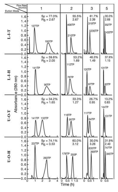
A series of studies was performed to examine the partition efficiency of the spiral tube support assembly in the separation of dipeptides. Fig. 3 shows a set of chromatograms obtained from an STS assembly consisting of about 40 m of 1.6 mm I.D. FEP (fluorinated ethylene propylene copolymer) tubing in 9 spiral layers with a total capacity of 103 ml as previously reported [6]. Similar to the results obtained from the spiral disk assembly [2], two elution modes, L-I-T and U-O-H give the best separation. Partition efficiency in the dipeptides by the present separation is found to be comparable to those obtained from the spiral disk assembly consisting of 8 disks. However, this plain spiral tube assembly shows low partition efficiency for proteins as expected from the previous results obtained from the spiral disk assembly.
Fig. 3.
Dipeptide separation with the plain spiral tube assembly
Apparatus: Type-J coil planet centrifuge with 10 cm revolution radius; separation column: plain spiral tube assembly consisting of 9 spiral layers of ca 40 m long, 1.6 mm I.D. FEP tube with a total capacity of 103 ml; solvent system: 1-butanol-acetic acid-water (4:1:5, v/v); Elution mode: defined in the text; sample: Trp-Tyr (1.25mg) and Val-Tyr (5 mg) in 1 ml of upper phase; revolution speed: 800 rpm; detection: 280 nm. In L-I-T and L-I-H, the first peaks represent Val-Tyr and the second peaks, Trp-Tyr while in U-O-T and U-O-H, the first peaks represent Trp-Tyr and the second peaks, Val-Tyr.
3.3. Separation of proteins and dipeptides with the STS with cross-pressed tubing
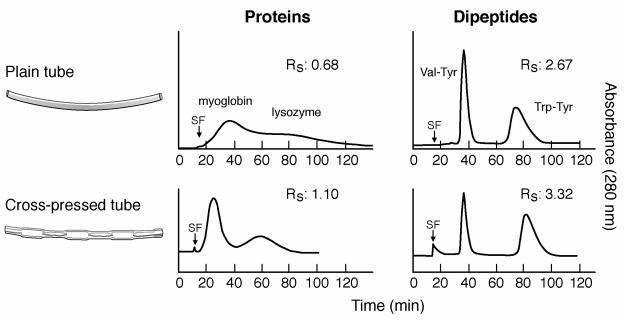
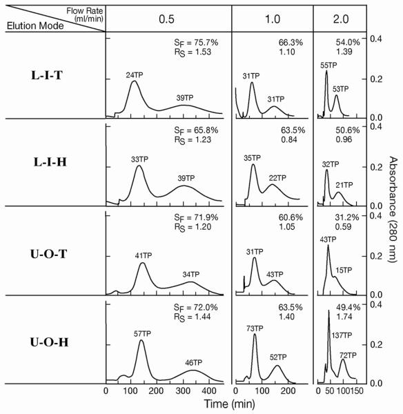
In order to improve the protein separation, 1-cm length presses were made with pliers at 90° angles along the tubing forming a flattened continuously skewed channel which would interrupt the laminar flow of the two phases. This cross-pressing process reduced the total column capacity from 103 ml to 95 ml. The cross-pressing effects on partition efficiency of test samples are shown in Fig. 4 where chromatograms of proteins and dipeptides obtained from the spiral column assemblies made from plain and cross-pressed tubes are compared. In the protein separation, the plain spiral tube assembly yields the peak resolution (RS) of 0.68 which is improved to 1.10 or over 2.6 times in partition efficiency in the cross-pressed STS. In the dipeptide separation, the cross-pressed STS also gives higher peak resolution despite the reduced column length due to less capacity. The results of protein separation obtained by the cross-pressed STS are shown in Fig. 5 where a set of chromatograms are arranged according to the elution modes and the applied flow rates. The partition efficiency in terms of theoretical plate number and peak resolution and retention of the stationary phase are also listed in Table 1. As in the peptide separation obtained from the plain STS, two elution modes of L-I-T and U-O-H yielded the better separation in both peak resolution and stationary phase retention. Two protein peaks were well resolved at a high flow rate of 2 ml/min.
Fig. 4.
Separation of proteins and dipeptides by plain spiral tube and cross-pressed tube assemblies. Apparatus: type-J coil planet centrifuge with 10 cm revolution radius; separation column: plain spiral tube assembly: 9 spiral layers of ca 40 m long, 1.6 mm I.D. FEP tube with a total capacity of 103 ml; cross-pressed spiral tube assembly: 9 spiral layers of ca 40 m long, 1.6 mm I.D. FEP tubing cross-pressed at 1 cm interval with 95 ml capacity; Protein separation: Solvent system: 12.5% (w/w)PEG1000-1.25%(w/w) potassium phosphate in water: for dipeptide separation: sample: lysozyme and myoglobin, each 5 mg in 1 ml of upper phase; elution mode: L-I-T, flow rate: 1 ml/min; detection: 280 nm. revolution: 800 rpm. Dipeptide separation: elution mode: L-I-T, flow rate 2 ml/min; other conditions are described in Fig. 3. SF: solvent front.
Fig. 5.
Protein separation by cross-pressed spiral tube assembly.
Experimental conditions are as described in Fig. 4. In L-I-T and L-I-H, the first peaks represent myoglobin and the second peaks, lysozyme while in U-O-T and U-O-H, the first peaks represent lysozyme and the second peaks, myoglobin.
Table 1.
Experimental conditions and separation efficiencies of proteins with 1.6 mm ID PTFE cross-pressed coil with 95 ml capacity at 800 rpm
| Elution mode | Flow rate (ml/min) |
T P (1st/2nd peaks) | Rs | SF (%) |
|---|---|---|---|---|
| L-I-T (CCW) | 0.5 | 24/29 | 1.53 | 75.7 |
| 1 | 31/31 | 1.10 | 66.3 | |
| 2 | 55/53 | 1.39 | 54.0 | |
| L-I-H (CW) | 0.5 | 33/39 | 1.23 | 65.0 |
| 1 | 35/22 | 0.84 | 63.5 | |
| 2 | 32/21 | 0.96 | 50.6 | |
| U-O-T (CW) | 0.5 | 41/34 | 1.20 | 71.9 |
| 1 | 31/43 | 1.05 | 60.6 | |
| 2 | 43/15 | 0.59 | 31.2 | |
| U-O-H (CCW) | 0.5 | 57/46 | 1.44 | 73.0 |
| 1 | 73/52 | 1.40 | 63.5 | |
| 2 | 137/72 | 1.74 | 49.4 |
L-I-T: lower mobile phase pumped into the inner tail terminal; L-I-H: lower mobile phase pumped into the inner head terminal; U-O-T: upper mobile phase pumped into the outer tail terminal; U-O-H: upper mobile phase pumped into the outer head terminal; direction of rotation viewing the spiral disk :CCW, counterclockwise rotation; CW, clockwise rotation; TP: theoretical plate number; RS: peak resolution; SF(%); % stationary phase retention; 1st peak: myoglobin in L-I-T or L-I-H and lysozyme in U-O-T or U-O-H; 2nd peak: lysozyme in L-I-T or L-I-H and myoglobin in U-O-T or U-O-H.
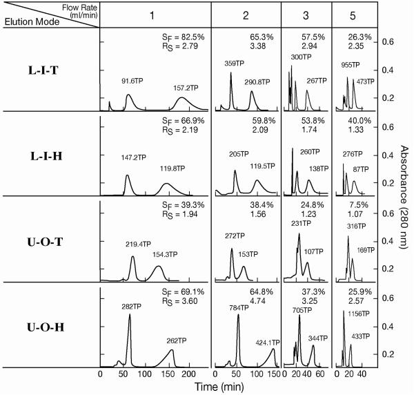
The results of dipeptide separation with the cross-pressed spiral tube assembly are shown in Fig. 6 and Table 2. The data obtained from the plain spiral tube assembly under the same experimental conditions are shown in the parentheses for comparison. In most separations RS values obtained from the cross-pressed STS is greater than those from the plain STS. Among all elution modes the elution mode of U-O-H shows the best peak resolution (RS) which exceeds peak resolution (RS= 3.2) between the corresponding two peaks obtained from the spiral disk assembly [2].
Fig. 6.
Dipeptide separation by cross-pressed spiral tube assembly.
Experimental conditions are described in Fig. 4. In L-I-T and L-I-H, the first peaks represent Val-Tyr and the second peaks, Trp-Tyr while in U-O-T and U-O-H, the first peaks represent Trp-Tyr and the second peaks, Val-Tyr.
Table 2.
Experimental conditions and separation efficiencies of dipeptides with 1.6 mm ID PTFE cross-pressed spiral tube with 95 ml capacity at 800 rpm
| Elution mode | Flow rate (ml/min) |
TP for1st/2nd peaks* | Rs | SF (%) |
|---|---|---|---|---|
| L-I-T (CCW) | 1 | 92/157 (127/193) | 2.79 (2.67) | 82.5 (77.0) |
| 2 | 359/291 (400/210) | 3.38 (2.67) | 65.3 (55.5) | |
| 3 | 300/267 (319/235) | 2.94 (2.39) | 57.5 (61.7) | |
| 5 | 955/473 (352/433) | 2.35 (2.68) | 26.3 (30.0) | |
| L-I-H (CW) | 1 | 147/120 (141/90) | 2.19 (2.05) | 66.9 (59.8) |
| 2 | 205/119 (112/76) | 2.09 (1.69) | 59.8 (53.2) | |
| 3 | 260/138 (120/67) | 1.74 (1.49) | 53.8 (46.3) | |
| 5 | 276/87 (131/63) | 1.33 (1.15) | 40.0 (37.9) | |
| U-O-T (CW) | 1 | 320/154 (141/133) | 1.94 (1.65) | 39.3 (34.2) |
| 2 | 212/153 (118/95) | 1.56 (1.27) | 38.4 (33.3) | |
| 3 | 182/83 (117/64) | 1.23 (0.95) | 24.8 (26.7) | |
| 5 | 316/169 (144/131) | 1.07(0.83) | 7.5 (13.2) | |
| U-O-H (CCW) | 1 | 282/262 (237/263) | 3.60 (3.53) | 69.1 (74.1) |
| 2 | 784/424 (178/355) | 4.74 (3.12) | 64.8 (60.0) | |
| 3 | 708/344 (635/369) | 3.25 (3.28) | 37.3 (30.0) | |
| 5 | 1156/433 (747/345) | 2.57 (2.40) | 25.9 (31.9) |
numbers in the parentheses are the corresponding date obtained from a normal tubing.
L-I-T: lower mobile phase pumped into the inner tail terminal; L-I-H: lower mobile phase pumped into the inner head terminal; U-O-T: upper mobile phase pumped into the outer tail terminal; U-O-H: upper mobile phase pumped into the outer head terminal; direction of rotation viewed from the top of the spiral disk :CCW, counterclockwise rotation; CW, clockwise rotation; TP: theoretical plate number; RS: peak resolution; SF(%); % stationary phase retention; 1st peak: val-tyr in L-I-T or L-I-H and trp-tyr in U-O-T or U-O-H; 2nd peak: trp-tyr in L-I-T or L-I-H and val-tyr in U-O-T or U-O-H.
3.4. Pressed tubing in 4 radial grooves of the STS
As mentioned above, the present design of the spiral tube assembly has a limited number of spiral layers because the transfer tubing lies between the spiral layers. To fit more layers into the assembly can be done by pressing the tubing in the 4 radial grooves with a specially made tool that holds 2 or 4 inserts used to press down the tubing. This process improves the partition efficiency of the STS in the following three different ways: 1) It increases the number of spiral layers accommodated in the support; 2) The dead space in the transfer tubing segment is reduced; and 3) the extra compressing in this radial return segment in each layer further interrupts the laminar flow.
In Table 3 is shown the results of protein separation with the 4-groove compressed spiral tube assembly at various revolution speeds at a flow-rate of 2 ml/min in the two optimum elution modes of L-I-T and U-O-H. In both elution modes, peak resolution (RS) increases with the applied revolution speeds, exceeding RS = 2 at 1200 rpm with a high retention of the stationary phase of over 60 %. In Table 4 are the results of dipeptide separation with the same spiral tube at various flow rates ranging from 1 ml/min to 5 ml/min all at the revolution speed of 800 rpm. The data in the parentheses are those obtained from the plain spiral tube assembly (see Fig. 3) for comparison. It clearly indicates that the 4-groove compressed STS shows substantially higher peak resolution mainly due to the increased number of spiral layers from 9 to 13 which increased the column capacity from 90 ml to 130 ml.
Table 3.
Experimental conditions and separation efficiencies of proteins with 1.6 mm ID PTFE tubing compressed at 4 radial grooves at 2 ml/min flow rate
| Elution mode | rpm | TP (1st/2nd peaks) | Rs | SF (%) |
|---|---|---|---|---|
| L-I-T (CCW) | 600 | 50/42 | 0.86 | 54.2 |
| 800 | 81/57 | 1.23 | 52.4 | |
| 1000 | 147/138 | 1.96 | 67.8 | |
| 1200 | 212/146 | 2.25 | 67.2 | |
| U-O-H (CCW) | 600 | 132/37 | 0.72 | 33.9 |
| 800 | 144/67 | 1.48 | 58.3 | |
| 1000 | 247/121 | 1.85 | 64.2 | |
| 1200 | 441/150 | 2.53 | 73.0 |
L-I-T: lower mobile phase pumped into the inner tail terminal; U-O-H: upper mobile phase pumped into the outer head terminal; direction of rotation viewing the spiral disk :CCW, counterclockwise rotation; TP: theoretical plate number; RS: peak resolution; SF(%); % stationary phase retention; 1st peak: myoglobin in L-I-T and lysozyme in U-O-H; 2nd peak: lysozyme in L-I-T and myoglobin in U-O-H.
Table 4.
Experimental conditions and separation efficiencies of dipeptides in a spiral column with 1.6 mm ID coil with compressed in the 4 radial grooves at 800 rpm (Data obtained from non-compressed spiral column are shown in parentheses for comparison)
| Elution mode | Flow rate (ml/min) |
TP of 1st/2nd peaks | Rs | SF (%) |
|---|---|---|---|---|
| L-I-T (CCW) | 1 | 180/207 (127/93) | 3.55 (2.67) | 77.5 (77.0) |
| 2 | 490/222 (400/210) | 3.35 (2.67) | 60.0 (55.5) | |
| 3 | 514/292 (319/235) | 3.13 (2.39) | 47.2 (61.7) | |
| 5 | 476/443 (352/433) | 2.67 (2.17) | 39.4 (43.3) | |
| L-I-H (CW) | 1 | 206/125 (141/90) | 2.40 (2.05) | 52.0 (59.8) |
| 2 | 146/100 (112/76) | 1.93 (1.69) | 50.4 (53.2) | |
| 3 | 212/109 (120/67) | 1.88 (1.49) | 40.0 (46.3) | |
| 5 | 240/116 (131/63) | 1.65 (1.15) | 34.6 (37.9) | |
| U-O-T (CW) | 1 | 208/181 (141/133) | 1,92 (1.65) | 56.8 (34.2) |
| 2 | 176/145 (118/95) | 1.60 (1.27) | 50.4 (33.3) | |
| 3 | 207/189 (117/64) | 1.46 (0.95) | 53.4 (26.7) | |
| 5 | 243/162 (144/131) | 1.23 (0.83) | 31.4 (13.2) | |
| U-O-H (CCW) | 1 | 308/297 (237/263) | 3.92 (3.53) | 79.2 (74.1) |
| 2 | 414/355 (178/355) | 3.75 (3.12) | 74.6 (60.0) | |
| 3 | 576/425 (635/369) | 3.26 (3.26) | 55.0 (30.0) | |
| 5 | 1363/421(747/345) | 3.08 (2.40) | 47.3 (31.9) |
L-I-T: lower mobile phase pumped into the inner tail terminal; L-I-H: lower mobile phase pumped into the inner head terminal; U-O-T: upper mobile phase pumped into the outer tail terminal; U-O-H: upper mobile phase pumped into the outer head terminal; direction of rotation viewing the spiral disk :CCW, counterclockwise rotation; CW, clockwise rotation; TP: theoretical plate number; RS: peak resolution; SF(%); % stationary phase retention; 1st peak: val-tyr in L-I-T or L-I-H and trp-tyr in U-O-T or U-O-H; 2nd peak: trp-tyr in L-I-T or L-I-H and val-tyr in U-O-T or U-O-H.
3.5. Combined effects of cross-pressing and radial groove compression on partition efficiency
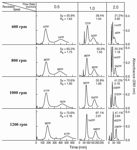
Finally the above two tubing modifications, cross-pressing and 4-radial channel compression, were combined to further improve the protein separation. Fig. 7 and Table 5 show the results obtained from the STS consisting of 15 spiral tubing layers of 0.35 mm I.D. with a total capacity of 85 ml. The separations were performed in the elution modes of L-I-T under various revolution speeds and flow rates. In all separations peak resolution (RS) increases with the applied revolution speeds from 600 rpm to 1200 rpm, The effect of flow rate on the peak resolution is more complex: at low range of revolution rates ranging from 600 rpm to 800 rpm, the peak resolution decreases as the flow rate is increased from 0.5 ml/min to 2.0 ml/min. However, at higher revolution rates over 1000 rpm, the peak resolution tends to increase with flow rates up to 2.0 ml/min. This indicates that the high efficiency of protein separation can be attained under a high rpm with a short separation time. Table 5 provides a set of data obtained by the 4-groove compressed plain STS in parentheses to evaluate the cross-pressing effect on partition efficiency. It clearly indicates that the partition efficiency is substantially improved by cross-pressing the spiral tubing.
Fig. 7.
Protein separation by cross-pressed and 4-way compressed tube assembly.
Separation column: 1. 35 mm ID PTFE cross-pressed spiral tube consisting of 15 spiral layers with 85 ml capacity. It was compressed along four radial grooves to improve the partition efficiency; sample, solvent system and other conditions: see Fig. 4 caption. In L-I-T and L-I-H, the first peaks represent myoglobin and the second peaks, lysozyme while in U-O-T and U-O-H, the first peaks represent lysozyme and the second peaks, myoglobin.
Table 5.
Separation of proteins by a spiral tube assembly with cross-pressed and 4-way compressed 1.35 mm ID PTFE tube with 15 spiral layers and a total capacity of 85 ml.
| Flow | 0.5 ml/min | 1 ml/min | 2 ml/min | ||||||
|---|---|---|---|---|---|---|---|---|---|
| rpm | TP | Rs | SF | TP | Rs | SF | TP | Rs | SF |
| 600 | 43/54(35/28* | 1.62 (1.04) | 55.9(63.0) | 72/50(56/30) | 1.04(1.13) | 39.4(54.3) | 144/46(46/25) | 0.82(0.58) | 21.2(19.7) |
| 800 | 96/66(27/32) | 1.75 (1.27) | 63.2(76.6) | 86/80(44/44) | 1.50(1.24) | 50.0(61.5) | 144/104(128/66) | 1.18(1.11) | 35.3(44.2) |
| 1000 | 51/76(40/91) | 1.90 (1.61) | 70.6(76.0) | 85/104(77/90) | 1.88 (1/78) | 55.9(71.2) | 228/275(88/138) | 2.18(1.81) | 41.2(56.7) |
| 1200 | 68/91 | 2.16 | 70.6 | 144/168(92/122) | 2.61 (2.29) | 67.1(71.2) | 455/249(133/191) | 2.64(2.06) | 47.1(59.6) |
TP: theoretical plate numbers for the first / second peaks; **Rs: Peak resolution; SF: % retention of the stationary phase; elution modea: L-I-T
Figures in parentheses indicate the date from 4-way compressed plain tube with 15 layers and 120 ml capacity.
4. Conclusions
Spiral tube HSCCC can be successfully applied to separation of proteins and dipeptides with a sufficient level of stationary phase retention using highly polar solvent systems which are not efficiently applied in the conventional multilayer coil. Although the plain spiral tube assembly can be used for separation of peptides, the partition efficiency is remarkably improved by modifying the tubing in two steps, cross-pressing along the whole length and pressing down the tubing in all the radial grooves. This is effective especially for protein separation using the polymer phase system. Since the present system gives a satisfactory retention of the stationary phase under a high flow rate of the mobile phase, efficient peak resolution can be attained in a short separation time. We believe that the present spiral tube assembly can be universally applied to all the two-phase solvent systems for HSCCC.
Acknowledgement
The authors are indebted to Messrs. Frank Sharpnak and Howard Metger in the NIH Machine Instrumentation Facility for their help in high-speed counter-current chromatography instrument and separation column fabrication.
References
- 1.Ito Y. CRC Rev. Anal. Chem. 1986;17:65–143. [Google Scholar]
- 2.Ito Y, Yang F-Q, Fitze PE, Sullivan JV. J. Liq. Chromatogr. Rel. Technol. 2003;26(910):1355–1372. [Google Scholar]
- 3.Albertsson PÅ. Partition of Cell Particles and Macromolecules. Wiley-Interscience; New York: 1984. [Google Scholar]
- 4.Ito Y, Qi L, Powell J, Sharpnack F, Metger H, Yost J, Cao X-L, Dong Y-M, Huo L-S, Zhu X, Li T. J. Chromatogr. A. 2007;1151:108–114. doi: 10.1016/j.chroma.2006.11.078. [DOI] [PubMed] [Google Scholar]
- 5.Ito Y, Clary R, Sharpnack F, Metger H, Powell J. J. Chromatogr. A. 2007;1172:151–159. doi: 10.1016/j.chroma.2007.09.078. [DOI] [PubMed] [Google Scholar]
- 6.Ito Y, Clary R, Powell J, Knight M, Finn T. J. Liq. Chromatogr. Rel. Technol. 2008;31:1346–1357. doi: 10.1080/10826070802019913. [DOI] [PMC free article] [PubMed] [Google Scholar]
- 7.Ito Y. Bethesda, MD, USA: 2007. (NIH 366.001). [Google Scholar]


