Abstract
Realistic modeling of medical interventions involving tool-tissue interactions has been considered to be a key requirement in the development of high-fidelity simulators and planners. Organ geometry, the soft-tissue constitutive laws, and boundary conditions imposed by the connective tissues surrounding the organ are some of the factors that govern the accuracy of medical intervention planning. In this study it is demonstrated that (for needle path planning) the organ geometry and boundary constraints surrounding the organ are the most important factors inuencing the deformation. As an example, the procedure of needle insertion into the prostate (e.g. for biopsy or brachytherapy) is considered. Image segmentation is used to extract the anatomical details from magnetic resonance images, while object-oriented finite element analysis (OOF) software is used to generate finite element (FE) meshes from the segmented images. Two-dimensional FE simulations that account for complex anatomical details along with relative motion between the prostate and its surrounding structure using cohesive zone models are compared with traditional simulation models having simple organ geometry and boundary constraints. Nodal displacements for these simpler models were observed to be up to 14 times larger than those obtained from the anatomically accurate models.
Keywords: anatomy, biopsy, brachytherapy, elasticity, finite element modeling, needle insertion, path planning, prostate
1 Introduction
The development of realistic surgical simulation systems requires accurate modeling of organs and their interactions with the surrounding organs and tissues, as well as the instrumentation tools. The benefits of tissue modeling are not only useful for training, planning, and practice of surgical and medical interventional procedures, but also for optimizing surgical tool design, creating “smart” instruments capable of assessing pathology, and understanding tissue injury mechanisms and damage thresholds.
Tool-tissue interaction models, complete simulator design approaches, specific medical applications, and training evaluation methods have been widely studied in the last two decades [17,19,28]. However, developing accurate models for surgical simulation is challenging. Biological tissues are generally inhomogeneous, anisotropic, and viscoelastic, and require complex experimental techniques to measure accurate force versus displacement characteristics in a laboratory. Further, development of organ models requires measurement of tissue properties in vivo, since organs have significantly different dynamics due to variations in temperature and blood circulation, which are impossible to precisely replicate during ex vivo experiments. Moreover, the task of choosing an appropriate constitutive law that describes the stress-strain response of the tissue under various loading conditions is not straightforward. On the other hand, using current medical imaging modalities such as x-ray, ultrasound, computed tomography (CT) scans, and magnetic resonance (MR) images, it is possible to determine organ geometry with a high level of accuracy. Complex boundary constraints and connective tissues that support the organs can also be observed, but to a much lesser degree.
Many surgical and interventional procedures require generating a plan prior to performing the task, which is typically performed with the aid of one or more of the imaging techniques listed above. The development of a patient-specific plan is critical in many surgical and interventional radiology procedures for drug delivery and biopsies, brachytherapies, and tumor ablations, during which needles must reach specific deep-seated locations inside the organ. Prostate brachytherapy is one example of a procedure that requires target-specific needle insertion, in which radioactive seeds are permanently implanted for cancer destruction. Transrectal ultrasound (TRUS) imaging or MR imaging with an endorectal coil are imaging modalities used clinically to guide the needle to its intended target. The success of the brachytherapy depends on the accuracy of placement of seeds, whose locations are determined during the planning stage of the procedure. Deformations caused during the pre-rupture phase, and also during needle insertion and retraction, can result in the needle missing its intended target. Thus, a method to predict the deformation of the organ prior to needle insertion would help clinicians in planning the path of the needle through tissue.
Patient-specific organ models useful for planning surgical or other interventional procedures and predicting tissue deformation require knowledge of the organ anatomy and its surrounding tissues, as well as information about the properties of all tissues involved in the surgical procedure. In this study, we hypothesize that organ geometry and boundary constraints play the most important role in determining the deformation of the organ during planning of procedures such as needle insertion. Several researchers have studied interactions between needles and soft tissues for surgical simulation and planning using continuum mechanics-based formulation techniques [1,2,4,7,10,13,16,23]. Among these studies, [2,13,16] specifically investigated needle insertion during prostate brachytherapy. All these studies presented methods to model the needle-tissue interaction forces and computation techniques required to enhance the simulation environment for real-time applications such as visual display of realistic organ deformations, haptic feedback, or surgical path planning, and did not consider detailed anatomical structures surrounding the organ. For example, Mohamed et al. [20] studied deformations of the prostate by considering a simple geometry (the prostate was an egg-shaped structure and while the rectum was a cylinder) and limited boundary conditions (sacrum and pubic arch) along with a nonlinear elasticity-based model. By considering some anatomical details, a nonlinear constitutive law, and statistical modeling techniques, their goal was to predict deformations of the prostate. In another example, Dehghan and Salcudean [9] compared the effects of linear and nonlinear finite element (FE) models on the mesh displacement during needle insertion and concluded that in the presence of asymmetric boundary conditions, noticeable differences result. All of the studies mentioned above emphasized the importance of realistic tissue properties in their work and few studies have also incorporated anatomical details in their models. However, no prior work has quantified the effects of both material properties and realistic anatomical details on accurate simulation of invasive procedures, such as needle insertion.
The present study shows that when an organ is subjected to displacements during needle insertion, the geometry and boundary constraints surrounding the organ dominate its deformation response, rather than the constitutive model. For this work, we considered the clinical application of needle insertion into the prostate (e.g. for biopsy or brachytherapy). We extracted pertinent anatomical structures from an MR image and generated a FE mesh in order to study the deformation of the prostate. In order to simulate the relative contact between the prostate and its surrounding tissue we employed cohesive zone models. Finally, we conducted sensitivity studies to show the effects of including of these boundary constraints in the model.
This paper is organized as follows: Section 2 presents representative cases that highlight the importance of geometry and boundary constraints for path planning surgical procedures. Section 3 applies these approaches specifically to needle insertion into the prostate and describes a method to generate FE meshes from MR images, while Section 4 presents the results of the sensitivity studies. Section 5 concludes by summarizing the results of this paper and providing potential areas for future work.
2 Study of Model Systems
The deformation of organs when interacting with interventional tools is fundamentally governed by the following factors: (1) organ geometry, (2) soft tissue properties, and (3) boundary constraints due to surrounding structures that support the organ. In surgical and other interventional procedures such as needle insertion, the clinician intends to reach a designated target. This implies that the input to the system is a displacement that results in deformation of the organ. In order to understand and quantify the significance of each of the items, we performed a set of simulation studies of model systems, in which two sets of geometries (square and circle), linear and nonlinear elasticity-based material properties, and different boundary conditions were compared. Table 1 shows the range of variables considered, and Figure 1 depicts the simulation cases considered with the boundary conditions and applied displacements.
Table 1.
Study of some of the factors affecting deformation of organs viz. geometry, boundary condition, and material behavior; combinations of the various factors result in 8 simulation cases with the following nomenclature: SFL, SFH, SPL, SPH, CFL, CFH, CPL, and CPH.
| Geometry | Square (S) | Circle (C) |
| Boundary condition | Fixed edge (F) | Partially constrained (P) |
| Material behavior | Linear elastic (L) | Hyperelastic (H) |
Fig. 1.
Simulation scenarios where the top edge was completely fixed and partially constrained edges, for objects with square and circular geometries. These represent a total of 8 simulation cases, in which the constitutive laws of the objects are described by linear elastic or hyperelastic models.
2.1 Constitutive Models
Most simulators today use a linear elastic assumption. For homogenous and isotropic models, the Cauchy stress tensor, σ, and the infinitesimal strain tensor, ε, given in component form, are related by
| (1) |
where E and ν are the Young’s modulus and Poisson’s ratio of the material, respectively, and δij is the Kronecker delta.
However, since biological organs undergo large strains, hyperelastic models are better suited to describe the constitutive behavior of soft tissues. Hyperelastic models are defined by a strain energy density function, W, associated with the material. The Mooney-Rivlin model is commonly used to approximate the response of rubber-like materials and some biological tissues [12], and was chosen for our analysis. For incompressible and isotropic materials, the Mooney-Rivlin model is of the form
| (2) |
where I1 and I2 are the invariants of the right Cauchy-Green deformation tensor, C = FTF, and F is the deformation gradient tensor. C1 and C2 are material properties. The Piola-Kirchhoff stresses in the material as a result of deformation can be obtained from
| (3) |
The Cauchy stress tensor, σ, and first Piola-Kirchhoff stress tensor, P, are related by
| (4) |
with J = det (F). The invariants of C are
| (5) |
| (6) |
| (7) |
2.2 Modeling Methods
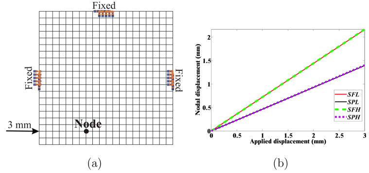
The simple square- and circular-shaped objects with distinctly different boundary constraints and elastic behavior provide example models that allow us to assess the importance of factors affecting the object’s deformation under applied displacement conditions. We performed two-dimensional (2D) FE simulations to quantify the relevance of these factors, namely object geometry, boundary condition, and material behavior. FE simulations of the 8 cases, as highlighted in Table 1 and Figure 1, were performed using the ABAQUS/Standard [37] simulation environment. The elements consisted of 8-node biquadratic plane strain quadrilaterals (ABAQUS element CPE8H) with nodes placed 1 mm apart for the square- and circular-shaped geometric objects. Plane strain FE models assume that the object is infinitely thick, so out-of-plane strains are not considered. This assumption is applicable for both models considered in this section and for the 2D simulation models presented in the following sections. Mesh resolution sensitivity studies were also performed to ensure that nodes placed 1 mm apart resulted in convergence of solution. Figure 3(a) provides as an example, a mesh of coarser resolution used for the square object with partially fixed boundary constraints and shows the location of applied displacement. Also shown in the figure is the location of one representative node whose displacements were scrutinized in detail.
Fig. 3.
Simulation conditions for the square object: (a) Example mesh where nodes are placed 5 mm apart for clarity, with partially constrained boundary conditions, applied displacement of 3 mm, and representative node. (b) Magnitude of nodal displacement for the 4 simulation cases (SFL, SPL, SFH, and SPH) at the representative node.
ABAQUS provides the capability to input both linear and nonlinear constitutive laws, along with user-defined boundary conditions and input displacements. For the linear elastic case, the Young’s modulus, E, and the Poisson’s ratio, ν, were set to 15 kPa and 0.49, respectively, which were reported in [27] as a linear elastic approximation to liver. For the nonlinear case, we choose the Mooney-Rivlin model, as stated in (2), and the material parameters C1 and C2 were assigned to be 3.46 kPa and 2.78 kPa, respectively, which were obtained via in vivo indentation studies on porcine liver [27].
2.3 Simulation Results for Model Systems
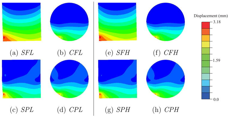
Contour plots depicting the resultant magnitude of the computed nodal displacements for the square- and circular-shaped geometries are shown in Figure 2. For both the square and circular geometric objects, the differences in boundary constraints result in varying displacement contour plots. Thus, the displacement fields are insensitive to material properties. However, the maximum increase in the von Mises stress, for a given geometry and boundary constraint, was observed to be 188.6%. This increase was between the CPL and CPH cases. Figure 3(a) depicts a representative node used to compare nodal displacements for the 4 simulation cases for the square object, while Figure 3(b) provides the magnitude of the displacements at the node. The maximum increase in nodal displacement between the SPL (or SPH) and SFL (or SFH) cases was observed to be 55.1% at the representative node.
Fig. 2.
Contour plots depicting the magnitude of the nodal displacements for the 8 simulation cases.
Needle insertion procedures are primarily displacement-driven problems, and our results indicate that the deformation response of the object is sensitive to boundary conditions surrounding it and not to its material properties. The SFL and SPL results are quantitatively different, as are SFL and CFL. This is because when the input to the system is displacement, the deformation of the object is relatively insensitive to the constitutive law. On the other hand, the stresses induced in the material are very different for the linear and nonlinear elastic models, since displacements are related to the stresses via the material properties, as shown in (1) and (4) for linear and nonlinear elastic models, respectively. This implies that for needle insertion procedures in which linear approximations of the tissue properties are available and needle bending is not of concern, greater emphasis must be placed on accurately modeling the organ geometry and tissues surrounding the organ.
3 Prostate Model
In the previous section, we compared square and circular geometric objects with simplified boundary constraints, which do not represent specific human organs. In this section, we apply the results obtained from the previous section to invasive procedures involving needle insertion, examples of which are biopsies, brachytherapies, and tumor ablations. In order to determine the importance of organ geometry and boundary constraints during a clinically relevant interventional procedure, we will examine needle insertion into the prostate for the purpose of brachytherapy. Prostate cancer is one of the most common malignancies among men and prostate brachytherapy represents one of the treatments options. This procedure consists of permanently placing radioactive seeds, most often 125I, inside the prostate via needles passing through the perineum, relying intensively on imaging guidance using TRUS [8] or MR imaging [30].
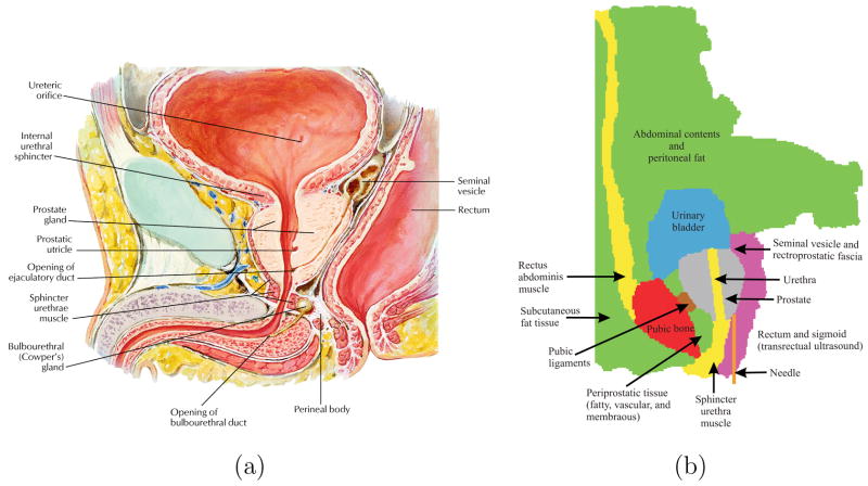
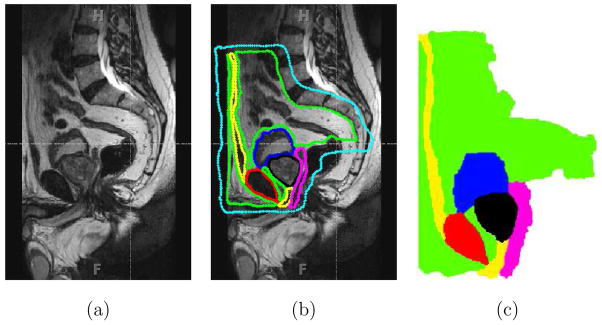
In order to model the boundary constraints of the prostate accurately, we need to identify the various anatomical structures, that surround the prostate and connect it to other organs. Figure 4(a) shows an anatomically accurate drawing of the male human pelvis in the sagittal plane, while Figure 4(b) provides a sagittal schematic of the various fatty tissue, ligaments, muscle, and bone surrounding the prostate based on an MR image (Figure 5). The urethra passes through the prostate and there are pubic ligaments attached to the prostate and the pubic bone. Also, shown in Figure 4(b) is the probable needle insertion location and applied displacement during insertion. In addition to identifying the boundary constraints of the prostate gland, it is necessary to model the geometry of the prostate as well as its surrounding tissue. In order to accomplish this, we extracted the geometric information from a sagittal view of an MR image. As opposed to other imaging modalities, MR images have larger field of view and produce the highest resolution of detail for pelvic soft tissues including prostate and surrounding structures, which in turn results in better segmentation of organ geometry. The MR image was acquired in a three-dimensional (3D) T2-weighted sequence of the male pelvis at 3.0 T magnetic field strength (TR: 1600 ms, TE: 115 ms, field of view: 35 cm, slice thickness: 1 mm with no gap) and was reconstructed in the sagittal plane. The various anatomical parts identified in Figure 4(b) and extracted from an MR image in Figure 5(b), were segmented using the random walker algorithm presented in [15]. Figure 5(c) shows the final segmented image generated from the input MR image, with the prostate in black. The random walker algorithm uses image intensities to segment an image without any prior model for the segmentation target. Therefore, it is dificult to categorize the accuracy of segmentation since the algorithm is a general purpose segmentation tool as opposed to being application specific. However, note that the random walker algorithm is an interactive technique and one can easily correct any errors in the segmentation results obtained in the first attempt. In particular, if the user is not satisfied with the required result, additional scribbles can be added to improve the segmentation. Due to the lack of ground truth segmentation, we performed a qualitative evaluation of our segmentation. More specifically, an experienced radiologist confirmed that the estimated segmentation (shown in Figure 5(c)) is of high level of accuracy. Moreover, there has been a comparison of the random walker algorithm with state of the art segmentation schemes and it has been shown that the algorithm’s performance is robust to changes in placement of the scribbles [29]. Further, in this study segmentation is an intermediate step in the process of developing FE meshes and the random walker algorithm was able to segment the MR image with desired accuracy levels.
Fig. 4.
Boundary constraints surrounding the prostate gland: (a) A close-up view of an anatomically accurate drawing of the male human pelvis [22]. (Reprinted from Netter Anatomy Illustration Collection, cElsevier Inc. All Rights Reserved. Top portion only of original image used.) (b) Sketch identifying the various tissues and organs. The urethra passes through the prostate and connects the urinary bladder to the sphincter urethra muscle, and the pubic ligaments connect the prostate to the pubic bone.
Fig. 5.
Segmentation of an MR image using the random walker algorithm [15]. (a) Sagittal view of the male pelvis. (b) Approximate location of the prostate and surrounding tissue identified, where the cyan color indicates the anatomy not of interest. (c) Segmented image, where the colors red, magenta, green, yellow, black, and blue signify bone, fascia, fat, muscle, prostate, and urinary bladder, respectively and also entered in Figure 4.
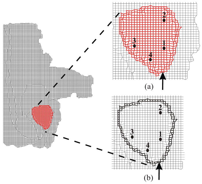
Software for conversion from segmented images to FE meshes exist, examples of which are [11,31]. Bharatha et al. [3] used the FE mesh generation algorithm described in [11] in order to generate a mesh while Crouch et al. [6] generated a FE mesh after image segmentation using the m-rep technique, which are a multiscale medial means for modeling 3D solid objects. Both studies only segmented the prostate gland. On the other hand, Sullivan et al. [31] developed a system to generate 3D elements and applied their technique to the abdominal region of a human body model and meshed the following regions: air, water, fat, bone, kidney, rectum, stomach, appendix, muscle, liver, bladder, prostate, and intestines. For our study, the FE mesh was generated from the segmented MR image using the open source object-oriented finite element analysis (OOF) [38] software developed by the US National Institute of Standards and Technology (NIST). OOF was designed to help materials scientists calculate macroscopic properties of materials from images of microstructures. The FE mesh generated consisted of 8090 4-node bilinear plane strain quadrilateral elements (ABAQUS element CPE4) as shown in Figure 6. Further, mesh resolution sensitivity studies were done to ensure that 8090 elements resulted in convergence of solution. The material properties assigned to the prostate and surrounding tissue are given in Table 2. It is dificult to acquire and test tissue samples of the prostate gland and surrounding organs. Further, most soft tissue constitutive model parameters are based on data acquired ex vivo (rather than in vivo) and there exists limited published data [12,35].
Fig. 6.
FE mesh of the prostate with its surrounding tissue generated from the segmented MR image used for simulation studies. (a) Close-up view of the simulation case where no cohesive elements surround the prostate (NoCoh). (b) Close-up view of the simulation case where prostate gland is surrounded by cohesive elements (in bold black) (Coh). Also shown are the data points at which nodal displacement were measured and the point of applied displacement used to simulate needle insertion.
Table 2.
Material properties of prostate and surrounding tissue were obtained from [5] and [35], respectively. These model constitutive parameters were derived from ex vivo tests. The properties of the urinary bladder were assumed to be that of water, with a bulk modulus, K = 2.2 GPa i.e. E = 3K (1 − 2ν).
| Tissue | E (kPa) | ν |
|---|---|---|
| Bone | 1.80 × 10⁶ | 0.3 |
| Fascia | 4249.78 | 0.45 |
| Fat | 3.25 | 0.45 |
| Ligament | 489.71 | 0.45 |
| Muscle | 29.85 | 0.45 |
| Prostate | 60.0 | 0.45 |
| Urinary bladder | 1.32 × 10⁴ | 0.499 |
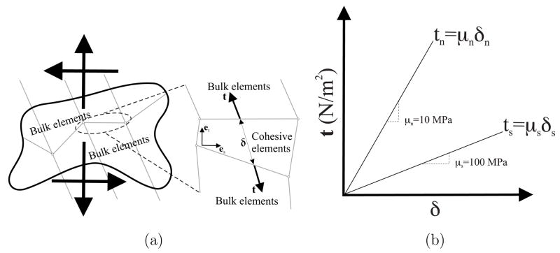
As the needle indents, punctures, and travels through the prostate, the gland slides and shears with respect to its surrounding tissue. In order to simulate this interaction between the prostate and its surrounding structure, we employ cohesive zone (also known as relative slip) models (Figure 7). Cohesive zone modeling techniques are commonly used to simulate interface failure in composite structures [36]. The cohesive zone is a mathematical approach to modeling the fact that work must be done to separate the two surfaces at an interface. This work is described in terms of a prescribed relationship between the forces required to separate the surfaces and the relative displacements of those surfaces. A detailed explanation of the numerical implementation of cohesive zone models is presented in [34]; cohesive zone elements are placed between bulk elements, as shown in Figure 7. Alternatively, modeling the relative slip between the prostate and its surrounding tissue could be simulated as a contact problem. This method is computationally challenging since the interaction forces and displacements between elements are computed on the basis of the inter-penetration distance between elements. Cohesive zone models are not plagued by such numerical instabilities and present an efficient solution to simulate interaction between elements.
Fig. 7.
The cohesive zone model. (a) A sketch depicting application of cohesive zone elements along the bulk element boundaries; tensile/compressive (normal) and shear displacements result in deformation of the cohesive elements. (b) Linear traction-strain laws with 10 MPa and 100 Pa normal elastic and shear elastic moduli, respectively.
The cohesive zone elements were defined around the prostate and are placed between continuum (bulk) elements, as shown in Figure 7(a). In our FE models, the cohesive zone was implemented using 4-node elements (ABAQUS element COH2D4). The applied displacement primarily results in sliding of the prostate with respect to its surrounding tissue, and cohesive zone elements open up and deform in order to simulate this behavior. All of the cohesive elements use a traction-strain law (Figure 7(b)), which defines the relationship between the vectorial tractions (force density vectors), t, and strains, δ, across the element. For unit original constitutive thickness of the cohesive element, which is different from the geometric thickness (which is typically close or equal to zero), the separation displacement is equal to the strain of the cohesive element. Thus, the tractions and strains are given by
| (8) |
where
| (9) |
and ts, tn and δs, δn are tractions and strains in the shear and normal directions, respectively. The description of the deformation and the traction evolution in these elements is governed by a linear traction law, as shown in Figure 7(b). Given that the relative tangential sliding is expected to be easier than normal separation or inter-penetration, we arbitrarily choose a tensile/compressive (normal) elastic modulus, μn, of 10 MPa and shear elastic modulus, μs, of 100 Pa. Changing the individual elastic moduli values by an order of magnitude did not produce significant variations in results. Experimentally-derived values for these moduli could be obtained from force-displacement measurements of the prostate interacting with its surrounding tissue, but are not currently available.
4 Sensitivity Studies for the Prostate Model
The deformation of the prostate gland during needle insertion can be classified into the following three distinct phases [18,24]:
First, the prostate undergoes elastic deformation as the tip of the needle indents the outer surface of the gland prior to puncturing the gland’s capsule. The prostatic capsule is a fibromuscular membrane encasing the prostate.
Second, the user-defined needle displacement induces a load on the prostate. When this load reaches a critical threshold the gland ruptures. The rupture process is characterized by a sharp and recognizable peak in the local organ deformation and load.
Third, following rupture, the needle can penetrate the tissue by cutting its surface. The fracture toughness of the material is the energy necessary to increase the area of fracture by an incremental amount and governs the propagation of rupture through tissue.
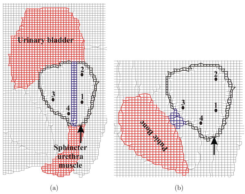
Consultations with clinicians and observations of needle insertion procedures indicate that maximum organ deformation occurs during the pre-rupture (first phase) stage of the prostate and the simulation of this phase is described in the paper. In order to simulate this process, a displacement boundary condition of 3.25 mm was applied to nodes on the outer periphery of the prostate as shown in Figure 6. The external boundary of the FE model (Figure 6) was fixed since this represents regions that are outside the human body or far away from the prostate gland, so they do not affect the prostate’s deformation. Further, the region marked as rectum and sigmoid in Figure 4(b) contains the transrectal probe or endorectal coil (depending on the imaging modality used for guiding the needle). These devices are relatively stiff and so are simulated as a fixed boundary condition. It should be noted that the MR image (Figure 5(a)), from which the FE models were generated, does not contain a transrectal probe. But an image with a transrectal probe could be segmented and meshed using the procedure described earlier. As highlighted in the anatomical drawing and sketch in Figures 4(a) and (b), respectively, the urethra is embedded in the prostate tissue and pubic ligaments are not visible in an MR image, but (because of their relative stifinesses) they should be accounted for in the simulation model. Figures 8(a) and (b) depict the elements assigned to be urethra muscle and pubic ligaments, respectively, and the cohesive zone has been modified to account for the urethra and pubic ligaments. The material properties for these tissues are given in Table 2.
Fig. 8.
Close-up views of FE meshes used for sensitivity studies. (a) Inclusion of the urethra (in blue) passing through the prostate (CohUr). (b) Pubic ligaments (in blue) connecting the prostate to the pubic bone (CohLig). The elements corresponding to the urethra and pubic ligaments have material properties associated with muscle and ligaments as provided in Table 2, respectively. The figure also shows the modified cohesive zone (in bold black) surrounding the prostate, location of applied displacement, and representative nodes.
In order to understand and compare the various modeling techniques we performed simulation studies with the following scenarios:
NoCoh: No cohesive zone or relative slip model employed (Figure 6(a)).
Coh: Cohesive zone model between the prostate and surrounding organs (Figure 6(b)).
CohUr: Cohesive zone model around the prostate and urethra passing through the prostate (Figure 8(a)).
CohLig: Cohesive zone model around the prostate and pubic ligaments attached to the prostate (Figure 8(b)).
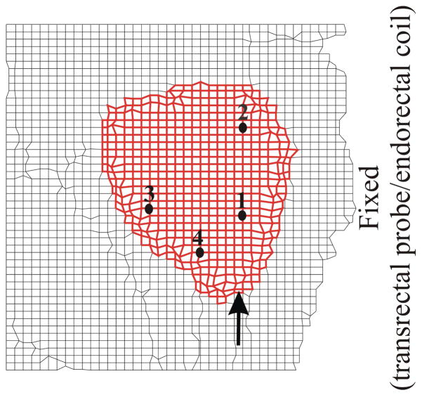
Crop: A simpler model that is a cropped version of our original mesh wherein the surrounding tissue properties had been assigned a single value of 30 kPa and the boundary mesh had been fixed only in the region to the right of the prostate, to signify the presence of the transrectal probe or endorectal coil (Figure 9). This simulation case represents a 2D approximation to traditionally performed modeling scenario for prostate brachytherapy where detailed organ geometry and boundary conditions are not considered [2,13,32].
Fig. 9.
Simplified mesh generated by cropping the original mesh with only the right-hand side fixed (Crop). Location of representative nodes are also shown.
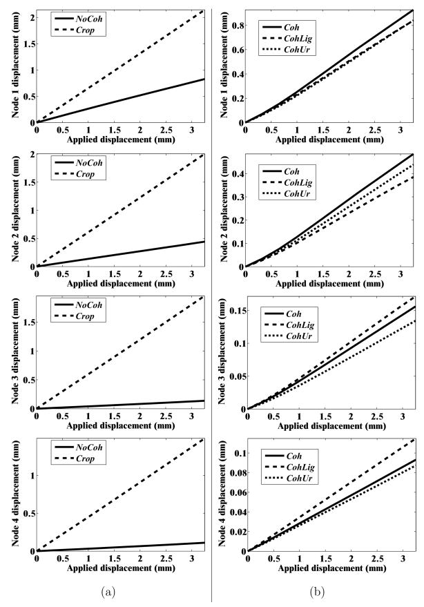
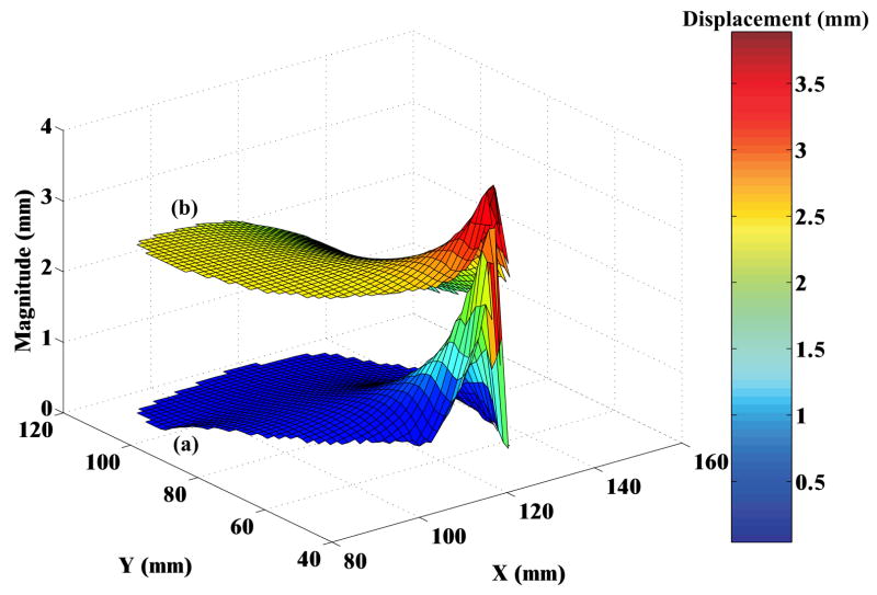
In order to quantify the deformation of the prostate mesh for the five simulation cases, we observed the nodal displacement at the same 4 nodes specified in Figures 6(a) and (b), 8(a) and (b), and 9. Figure 10 provides the nodal displacement for the 5 simulation cases. In Figure 10(a) we provide the nodal displacement for simulation cases NoCoh and Crop, model with detailed anatomy and cropped up mesh, respectively. The maximum nodal displacement at node 3 for Crop was 14 times larger than that observed for NoCoh. Figure 11 depicts the magnitude of prostate nodal displacement for both NoCoh and Crop simulation cases. The deformation of the nodes is similar for both cases close to the location of the input displacement, but further away the magnitudes of displacement are highly dissimilar. In Figure 10(b) we compare nodal displacements for the simulation cases Coh, CohUr, and CohLig. In addition to having complex geometry and boundary conditions, these simulation cases also include cohesive zones, the urethra passing through the prostate, and pubic ligaments connecting the prostate to the pubic bone, respectively. A 9.5% (at node 1) and 20.4% (at node 2) increase in maximum nodal displacement was observed for the CohUr and CohLig cases, respectively, when compared to Coh. Thus, in the 2D simulation cases, the inclusion of the urethra and pubic ligaments did not cause large differences in the nodal displacement. However, significant differences in nodal displacement are observed between the anatomically accurate versus simpler models.
Fig. 10.
Nodal displacement for the 5 simulation cases: (a) NoCoh and Crop (b) Coh, CohUr, and CohLig
Fig. 11.
Surface plots depicting the magnitude of nodal displacements for the prostate, where X and Y axes represent the nodal co-ordinates of the prostate in the FE model. (a) Simulation with complex anatomy and boundary conditions (NoCoh) and (b) simulation with simple organ geometry and boundary conditions (Crop). For both simulation cases relative motion between the prostate and surrounding tissue is not modeled.
5 Conclusion and Future Work
Biopsies, brachytherapies, and other needle insertion procedures are primarily displacement-driven interventional operations. This means that the clinician applies an input displacement to the needle in order to reach the target, and this applied displacement results in deformation of the organ. For one such task, our results show that the organ geometry and boundary constraints surrounding the organ (rather than the constitutive behavior of the tissue) dominate its deformation. We apply this approach to the clinical procedure of needle insertion into the prostate by identifying boundary constraints and tissue surrounding the prostate gland, and simulated the pre-rupture deformation of tissue. We compare our results to a case where the anatomy surrounding the prostate was not accurately defined, and our results show that the use of more detailed geometry results in significantly smaller displacements (by a factor of 14 at one representative point). It should be noted that this study does not attempt to equate greater or lesser nodal displacements to better performance of the model. Rather, it presents sensitivity studies in which simulation models of varying fidelity (in terms of realistic organ geometry and surrounding boundary constraints) are compared. We believe our study is the first to consider this level of sophistication in simulation by incorporating anatomical details and using the concept of cohesive zone models to account for relative slip between the prostate and surrounding tissue.
The objective of this research was to quantitatively demonstrate that anatomically valid organ geometry models and appropriate boundary constraints are essential for accurate simulation of organ deformation during invasive procedures such as, needle insertion into the prostate. Each procedure brings to bear different tissue constitutive models, geometry, and boundary conditions. The extent to which our hypothesis is valid for any specific procedure needs to be examined, and only then can its general validity be considered. The current study considered 2D organ models and future work should include 3D geometry and boundary constraints. There exist several challenges in going from 2D to 3D models, which include acquiring 3D MR image data sets, generation of 3D elements, 3D mesh modification to simulate needle insertion, visualization of 3D mesh deformation, and significant increase in computational time. Also, unlike OOF (which is developed by NIST) there does not exist a standard validated method to generate 3D FE meshes. Further, with changes in boundary condition as the needle interacts with tissue, the simulation of 3D contact and 3D cohesive zone models is an ongoing research topic. For boundary value problems in which the input is an applied displacement, the induced stresses in the system are intrinsically linked to the material properties. Thus, for surgical simulation applications where force is fed back to the user, the constitutive model of the organ and surrounding tissue should be studied in detail. In addition to accurate calculation of stresses developed, simulators with haptic feedback also require that the interaction forces be rendered in real time, which can be computationally challenging. Further, for needle insertion procedures in which the needle is exible and bends due to interactions with tissues [1,10,14,33], high-fidelity tissue models need to be considered. But for scenarios in which stiff needles are used, the boundary conditions govern the deformation of the organ.
To date, we have not compared the tissue deformation model to data from actual needle insertion tasks such as prostate biopsy or brachytherapy. Model validation will be addressed in future work, and could be accomplished by recording tissue deformation data from a sequence of ultrasound or MR images and comparing them to simulation data. The validation of the simulation model requires experiments in which a needle is inserted in a controlled manner (possibly by a robotic device) into the patient and organ deformation is quantitatively recorded by soft tissue registration. During these in vivo needle insertion experiments, cutting forces would also need to be separated from the puncture and friction forces. Further, advanced simulation environments requiring accurate tissue deformation models might need to incorporate tissue rupture models using concepts from fracture mechanics.
Nonetheless, our work does reiterate the fact and provides quantitative evidence that realistic geometry and boundary conditions are important for surgical simulation and planning. More importantly for surgical planning, the geometry and boundary conditions govern the deformation of the tissue. With existing medical imaging technology it is possible to extract pertinent patient-specific anatomical details prior to a surgical procedure. Most conventional techniques for measuring tissue properties are done ex vivo, unless it is possible to replicate in vivo conditions in an elaborate experimental setup (e.g. [26]), or by using specialized in vivo apparatus (e.g. [21]). Alternatively, non-invasive methods like elastography can be used to estimate relative stifiness of the tissue [25]. In order to predict deformation of the tissue, anatomical details derived from medical images could be fed into a simulation model containing approximate material properties of the tissue. This methodology could be the current “gold standard” for patient-specific surgical planning, until better techniques are available to measure tissue properties in vivo.
Acknowledgments
This work was supported by the National Institutes of Health Grant Nos. R01-EB002004 and R01-EB006435, National Science Foundation Grant No. EIA-0312551, and a Link Foundation Fellowship. The authors thank Andrew Douglas (Ph.D.), Gabor Fichtinger (Ph.D.), Ulrike Hamper (M.D.), Danny Song (M.D.), Li-Ming Su (M.D.), Dheeraj Singaraju, and Debjoy Mallick for their help and advice.
Footnotes
Publisher's Disclaimer: This is a PDF file of an unedited manuscript that has been accepted for publication. As a service to our customers we are providing this early version of the manuscript. The manuscript will undergo copyediting, typesetting, and review of the resulting proof before it is published in its final citable form. Please note that during the production process errorsmaybe discovered which could affect the content, and all legal disclaimers that apply to the journal pertain.
References
- 1.Abolhassani N, Patel RV. Deection of a exible needle during insertion into soft tissue. Proc. 28th IEEE EMBS Annual Int’l Conf.; New York, USA. 2006. pp. 3858–3861. [DOI] [PubMed] [Google Scholar]
- 2.Alterovitz R, Goldberg K, Pouliot J, Taschereau R, Hsu CI. Needle insertion and radioactive seed implantation in human tissues: simulation and sensitivity analysis. Proc. IEEE Int’l. Conf. on Robotics and Automation; Taipei, Taiwan. 2003. pp. 1793–1799. [Google Scholar]
- 3.Bharatha A, Hirose M, Hata N, Warfield SK, Ferrant M, Zou KH, Suarez-Santana E, Ruiz-Alzola J, D’Amico A, Cormack RA, Kikinis R, Jolesz FA, Tempany CM. Evaluation of three-dimensional finite element-based deformable registration of pre- and intra-operative prostate imaging. Medical Physics. 2001;28(12):2551–2560. doi: 10.1118/1.1414009. [DOI] [PubMed] [Google Scholar]
- 4.Bro-Nielsen M. Finite element modeling in surgery simulation. Proc IEEE. 1998;86(3):490–503. [Google Scholar]
- 5.Chi Y, Liang J, Yan D. Material sensitivity study of deformable organ registration. Medical Physics. 2006;33(2):421–433. doi: 10.1118/1.2163838. [DOI] [PubMed] [Google Scholar]
- 6.Crouch JR, Pizer SM, Chaney EL, Zaider M. Medially based meshing with finite element analysis of prostate deformation. 6th Int’l Conf. on Medical Image Computing and Computer Assisted Intervention. Lecture Notes in Computer Science 2878; Montreal, Canada. 2003. pp. 108–115. [Google Scholar]
- 7.Crouch JR, Schneider CM, Wainer J, Okamura AM. A velocity-dependent model for needle insertion in soft tissue. 8th Int’l Conf. on Medical Image Computing and Computer Assisted Intervention. Lecture Notes in Computer Science 3750; Palm Springs, USA. 2005. pp. 624–632. [DOI] [PubMed] [Google Scholar]
- 8.Daanen V, Gastaldo J, Giraud JY, Fourneret P, Descotes JL, Bolla M, Collomb D, Troccaz J. MRI/TRUS data fusion for brachytherapy. The Int’l Journal of Medical Robotics and Computer Assisted Surgery. 2006;2(3):256–261. doi: 10.1002/rcs.95. [DOI] [PubMed] [Google Scholar]
- 9.Dehghan E, Salcudean SE. Comparison of linear and non-linear models in 2D needle insertion simulation. 9th Int’l Conf. on Medical Image Computing and Computer Assisted Intervention. Workshop Proc. Computational Biomechanics for Medicine; Copenhagen, Denmark. 2006. pp. 117–124. [Google Scholar]
- 10.DiMaio SP, Salcudean SE. Needle insertion modeling and simulation. IEEE Trans Robotics and Automation. 2003;19(5):864–875. [Google Scholar]
- 11.Ferrant M, Warfield SK, Guttmann CRG, Mulkern RV, Jolesz FA, Kikinis R. 3D image matching using a finite element based elastic deformation model. 2nd Int’l Conf. on Medical Image Computing and Computer Assisted Intervention. Lecture Notes in Computer Science 1679; Cambridge, UK. 1999. pp. 202–209. [Google Scholar]
- 12.Fung YC. Biomechanics: Mechanical Properties of Living Tissues. 2. W. B. Springer-Verlag Inc; New York, USA: 1993. [Google Scholar]
- 13.Goksel O, Salcudean SE, DiMaio SP, Rohling R, Morris J. 3D needle-tissue interaction simulation for prostate brachytherapy. 8th Int’l Conf. on Medical Image Computing and Computer Assisted Intervention. Lecture Notes in Computer Science 3749; Palm Springs, USA. 2005. pp. 827–834. [DOI] [PubMed] [Google Scholar]
- 14.Glozman D, Shoham M. Image-guided robotic exible needle steering. IEEE Trans Robotics. 2007;23(3):459–467. [Google Scholar]
- 15.Grady L. Random walks for image segmentation. IEEE Trans Pattern Analysis and Machine Intelligence. 2006;28(11):1768–1783. doi: 10.1109/TPAMI.2006.233. [DOI] [PubMed] [Google Scholar]
- 16.Hing JT, Brooks AD, Desai JP. Reality-based needle insertion simulation for haptic feedback in prostate brachytherapy. Proc. IEEE Int’l. Conf. on Robotics and Automation; Orlando, USA. 2006. pp. 619–624. [Google Scholar]
- 17.Liu A, Tendick F, Cleary K, Kaufmann C. A survey of surgical simulation: applications, technology, and education. Presence: Teleoperators & Virtual Environments. 2003;12(6):599–614. [Google Scholar]
- 18.Mahvash M, Hayward V. Haptic rendering of cutting: a fracture mechanics approach. Haptics-e. 2001;2(3):1–12. [Google Scholar]
- 19.Misra S, Ramesh KT, Okamura AM. Modelling of tool-tissue interactions for computer-based surgical simulation: a literature review. Presence: Teleoperators & Virtual Environments. 2008;17(5) doi: 10.1162/pres.17.5.463. In Press. [DOI] [PMC free article] [PubMed] [Google Scholar]
- 20.Mohamed A, Davatzikos C, Taylor R. A combined statistical and biomechanical model for estimation of intra-operative prostate deformation. 5th Int’l Conf. on Medical Image Computing and Computer Assisted Intervention. Lecture Notes in Computer Science 2489; Tokyo, Japan. 2002. pp. 452–460. [Google Scholar]
- 21.Nava A, Mazza E, Kleinermann F, Avis NJ, McClure J. Determination of the mechanical properties of soft human tissues through aspiration experiments. 6th Int’l Conf. on Medical Image Computing and Computer Assisted Intervention. Lecture Notes in Computer Science 2878; Montreal, Canada. 2003. pp. 222–229. [Google Scholar]
- 22.Netter FH. Atlas of Human Anatomy. 4. W. B. Saunders Company; Philadelphia, USA: 2006. [Google Scholar]
- 23.Nienhuys H-W, van der Stappen FA. A computational technique for interactive needle insertions in 3D nonlinear material. Proc. IEEE Int’l. Conf. on Robotics and Automation; New Orleans, USA. 2004. pp. 2061–2067. [Google Scholar]
- 24.Okamura AM, Simone C, O’Leary MD. Force modeling for needle insertion into soft tissue. IEEE Trans Biomedical Engineering. 2004;51(10):1707–1716. doi: 10.1109/TBME.2004.831542. [DOI] [PubMed] [Google Scholar]
- 25.Ophir J, Alam SK, Garra BS, Kallel F, Konofagou EE, Krousko T, Merritt CRB, Righett R, Souchon R, Srinivasan S, Varghese T. Elastography: imaging the elastic properties of soft tissues with ultrasound. Journal Medical Ultrasonics. 2002;29(4):155–171. doi: 10.1007/BF02480847. [DOI] [PubMed] [Google Scholar]
- 26.Ottensmeyer MP, Kerdok AE, Howe RD, Dawson SL. The effects of testing environment on the viscoelastic properties of soft tissues. Int’l Symposium on Medical Simulation. Lecture Notes in Computer Science 3078; Cambridge, USA. 2004. pp. 9–18. [Google Scholar]
- 27.Samur E, Sedef M, Basdogan C, Avtan L, Duzgun O. A robotic indenter for minimally invasive measurement and characterization of soft tissue response. Medical Image Analysis. 2007;11(4):361–373. doi: 10.1016/j.media.2007.04.001. [DOI] [PubMed] [Google Scholar]
- 28.Satava RM. Accomplishments and challenges of surgical simulation. Surgical Endoscopy. 2001;15(3):232–241. doi: 10.1007/s004640000369. [DOI] [PubMed] [Google Scholar]
- 29.Sinop AK, Grady L. A seeded image segmentation framework unifying graph cuts and random walker which yields a new algorithm. Proc. IEEE Int’l. Conf. on Computer Vision; Rio de Janeiro, Brazil. 2007. pp. 1–8. [Google Scholar]
- 30.Susil RC, Camphausen K, Choyke P, McVeigh ER, Gustafson GS, Ning H, Miller RW, Atalar E, Coleman CN, Ménard C. System for prostate brachytherapy and biopsy in a standard 1.5 T MRI scanner. Magnetic Resonance in Medicine. 2004;52(3):683–687. doi: 10.1002/mrm.20138. [DOI] [PMC free article] [PubMed] [Google Scholar]
- 31.Sullivan JM, Charron G, Paulsen KD. A three-dimensional mesh generator for arbitrary multiple material domains. Finite Elements in Analysis and Design. 2000;25(3):219–241. [Google Scholar]
- 32.Wang X, Fenster A. A virtual reality based 3D real-time interactive brachytherapy simulation of needle insertion and seed implantation. Proc. IEEE Int’l Symposium Biomedical Imaging: From Nano to Macro; Arlington, USA. 2004. pp. 280–283. [Google Scholar]
- 33.Webster RJ, III, Kim JS, Cowan NJ, Chirikjian GS, Okamura AM. Nonholonomic modeling of needle steering. Int’l J Robotics Research. 2006;25(3–6):509–525. [Google Scholar]
- 34.Xu XP, Needleman A. Numerical simulations of fast crack growth in brittle solids. J Mechanics Physics Solids. 1994;42(9):1397–1434. [Google Scholar]
- 35.Yamada H. Strength of Biological Materials. 1. The Williams & Wilkins Company; Baltimore, USA: 1970. [Google Scholar]
- 36.Zhang H, Ramesh KT, Chin ESC. Effects of interfacial debonding on the rate-dependent response of metal matrix composites. Acta Materialia. 2005;53(17):4687–4700. [Google Scholar]
- 37.Simulia (Dassault Systèmes) Rising Sun Mills, 166 Valley Street, Providence, RI 02909 USA. http://www.simulia.com/
- 38.National Institutes of Standards and Technology. 100 Bureau Drive, Stop 1070, Gaithersburg, MD 20899 USA. http://www.ctcms.nist.gov/oof/


