Abstract
K0.5Na0.5NbO3-(KNN) based lead free materials have been found to exhibit good piezoelectric properties (d33∼250 pC∕N) due to the orthorhombic-tetragonal polymorphic phase transition (PPT) temperature compositionally shifted downward to near room temperature. However, associated with the PPT are issues of temperature and domain instability, making them impractical for applications. In this work, CaTiO3 (CT) was used to effectively shift the PPT downward in effort to mitigate these issues. As expected, CT modified KNN based materials exhibited nearly temperature independent properties (−50∼200 °C) and fatigue-free behavior, together with its relatively high d33 value of ∼200 pC∕N, make the CT modified KNN based materials excellent candidates for lead free actuators and transducers.
K0.5Na0.5NbO3 (KNN) lead free piezoelectric ceramics were first reported in 1959.1 Their relatively low piezoelectric coefficient, d33∼80 pC∕N, and difficulties in fabrication made them unattractive for practical applications.1 Recently, high piezoelectric coefficients d33>200 pC∕N have been reported for modified KNN using LiNbO3 (LN), LiSbO3 (LS), LiTaO3 (LT), BaTiO3, SrTiO3, etc., with the added advantage of improved processibility.2, 3, 4, 5, 6, 7, 8, 9, 10, 11, 12, 13, 14, 15, 16, 17, 18, 19 However, the enhanced properties are the result of compositionally shifting the orthorhombic to tetragonal polymorphic phase transition (PPT) downward from ∼200 °C to near room temperature.6, 7, 8, 19 Associated with a PPT are strong temperature dependent properties and degradation associated with domain instability during thermal cycling between the two distinct different ferroelectric domain states, making them impractical for various applications.6
Based on the above, it is desirable to shift the PPT out of the application temperature range (usually −50∼200 °C), in order to improve thermal stability and mitigate property degradation, while maintaining high piezoelectric properties. It was reported that the addition of LN, LT, or LS in KNN effectively increased the piezoelectric properties owing to the shift of the PPT to near room temperature, but further shifts downward to below room temperature could not be achieved owing to solubility limitations (∼6%–8%), where excess addition(s) lead to undesirable second phase(s), thus deteriorating the properties.2
Following the work on modified BaTiO3,20, 21 the first lead free piezoelectric ceramic, the addition of CaTiO3 (CT) was proposed to modify the KNN-based systems, as such to further shift the orthorhombic to tetragonal PPT downward to below room temperature, achieving a more temperature stable piezoelectric material.17
The conventional solid-state reaction method was used to prepare the KNN-based materials with and without CT modifications. High purity oxides and∕or carbonates K2CO3, Na2CO3, Li2CO3, Nb2O5, Sb2O5, and CT were used as the starting materials and weighed according to the nominal compositions. After vibratory milling in anhydrous ethanol, the mixed powders were calcined at 880 °C for 2 h, and then the synthesized materials were milled again and followed by the addition of binder. The granulated powders were pressed into pellets with 12 mm in diameter prior to the removal of the binder. The pellets were sintered at 1120–1180 °C in sealed alumina crucibles for 2 h. X-ray powder diffraction (XRD) analysis was performed on ground sintered samples using Cu Kα radiation (PANalytical X’Pert PRO). Narrow region slow scanning was employed using Si as a standard and the test condition was 0.01∕step with 20 s. The diffraction spectrum was refined using the X’PERT HIGHSCORE PLUS 2.0 software.22 Samples for electrical measurements were polished parallel and electroded using fire-on silver paste (DuPont 6160). Polarization of the samples was achieved by the application of an electric field of 50–60 kV∕cm at 60 °C, with the samples allowed to age 24 h prior to electrical measurements. Samples with dimensions of 3×12×0.5 mm3 were used to measure the dielectric permittivity and piezoelectric coefficient d31 using an HP4194A impedance analyzer according to IEEE standards.23 Thermal cycling studies were carried out over the temperature range of −50∼200 °C. Samples for polarization fatigue studies used disk samples being 10 mm in diameter and 0.5–1 mm in thickness. The samples were first annealed at 500 °C for 2 h to release any mechanical stress generated during the grinding and polishing processes, and then fire-on silver paste applied as the electrode. A modified Sawyer–Tower circuit and linear variable differential transducer driven by a lock-in amplifier (Stanford Research System, model SR830) were used to determine the polarization hysteresis and strain behavior. A high electric field of 50 kV∕cm (two to three times of the coercive field of the samples) with a triangular bipolar wave form and frequency of 1 Hz was generated using a computer controlled high voltage amplifier (Trek Model 609C-6). During the studies, the samples were emerged in Fluorinert™ type insulating fluid to avoid electrical arcing, while maintaining the sample at room temperature.
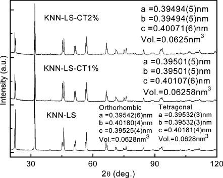
Figure 1 shows the XRD pattern for KNN-LS and CT modified KNN-LS materials at room temperature. The refinement of the tetragonal and orthorhombic structures for the KNN-LS material gave similar results, with unit cell volumes of 0.0628 nm3, demonstrating that the coexistence of both phases are plausible for KNN-LS at room temperature. This is in agreement with the dielectric-temperature behavior (as shown in the Fig. 2 inset), where the orthorhombic-tetragonal PPT was found to be located around room temperature.6 It is observed from Fig. 1 that the CT modified KNN-LS ceramics possess pure tetragonal perovskite phase, due to the PPT being shifted downward to −15 to −40 °C with 1–2 wt % CT additions, as can be seen in the inset of Fig. 2.17 The c∕a ratio was found to be on the order of 1.015 with a unit cell volume on the order of 0.06258 and 0.0625 nm3, for KNN-LS with 1% and 2% CT additions, respectively. The unit cell volume decreased due to the addition of CT in KNN-LS material, since the ionic radius of Ca2+ is smaller than K+ and Na+, while the ionic radius of Ti4+ is smaller than Nb5+, indicating that the CT goes into the perovskite crystal lattice.
Figure 1.
XRD pattern for pure and CT modified KNN-LS materials.
Figure 2.
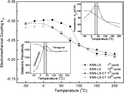
Electromechanical coupling k31 as a function of temperature for pure and CT modified KNN-LS materials on the first and tenth thermal cycle (insets show the temperature and thermal cycling behavior of dielectric permittivity and piezoelectric coefficient).
Figure 2 presents the temperature behavior and thermal cycling characteristics of the electromechanical coupling factor k31, for KNN-LS and CT modified KNN-LS materials in the temperature range of −50∼200 °C. The small insets in Fig. 2 give the thermal cycling of the dielectric permittivity and piezoelectric coefficient d31, respectively. It is observed that the temperature characteristics of the piezoelectric coefficient and dielectric permittivity for KNN-LS exhibits a local anomaly at room temperature due to the PPT, while the CT modified counterpart(s) exhibits a linear decrease over this temperature range. The data for the first cycle and the tenth cycle are also given in the figures. It is worthy to note that the effect of the thermal cycling within the tetragonal and orthorhombic phases is significantly different. As shown in Fig. 2, there are no variation in piezoelectric and dielectric properties for the KNN-based ceramics within the tetragonal phase, however, in the orthorhombic and∕or phase coexistence regions of the KNN-LS material, the d31 value is found to decrease by 6% after ten cycles due to domain instability during thermal cycling. The electromechanical coupling factor k31 exhibits a similar tendency with a peak value found to occur at room temperature for KNN-LS ceramic, decreasing by 20%–30% after thermal cycling in the orthorhombic region. In the tetragonal region, the change was found to be on the order of <5% after cycling. The values for the CT modified KNN-LS ceramics, however, are found to linearly decrease with increasing temperature, maintaining similar values after thermal cycling.
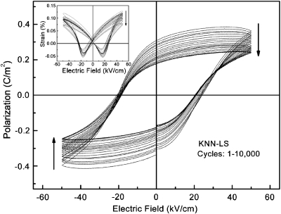
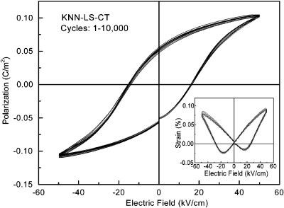
Figures 34 show the bipolar polarization hysteresis as a function of switching cycle for pure and CT modified KNN-LS ceramics, respectively. The electric field-strain behavior is also investigated and gives in the small insets. From Fig. 3, it can be observed that the KNN-LS material exhibits fatigue behavior, whereupon the spontaneous and remnant polarizations are found to decrease by 50%, with a corresponding decrease in strain levels. For the CT modified materials, however, no fatigue behavior up to 10 000 switching cycles is observed, as shown in Fig. 4. It is also observed from Figs. 34 that the saturated polarization of KNN-LS is on the order of 39 μC∕cm2, much higher than the value of the CT modified ceramics (∼11 μC∕cm2). The high saturated polarization is expected in KNN-LS material due to the coexistence of tetragonal and orthorhombic phases near the PPT at room temperature, which is related to the summation of possible crystallographic orientations, with 12 ⟨110⟩ spontaneous polarization (Ps) directions in an orthorhombic phase and six ⟨001⟩ Ps directions in the tetragonal phase.19
Figure 3.
Polarization hysteresis as a function of switching cycles, for KNN-LS material (inset shows the strain behavior).
Figure 4.
Polarization hysteresis as a function of switching cycles, for CT modified KNN-LS material (inset shows the strain behavior).
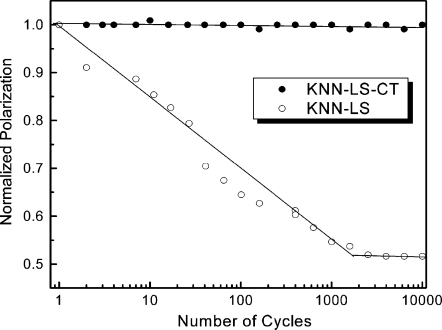
Figure 5 shows the normalized polarization as a function of switching cycle for pure and CT modified KNN-LS materials, where no electrical fatigue is observed for the CT modified material, while fatigue follows a logarithmic decay with switching for the pure KNN-LS material. Analogous to other perovskite systems with coexisting phases at room temperature,24 90° domain switching occurs much easier in the KNN-LS ceramics when compared to the CT modified samples, owing to the coexistence of tetragonal and orthorhombic phases. It is widely accepted that bipolar fatigue generates microscopic defects and∕or defect clusters in bulk ceramics, effectively pinning 90° domain wall motion, resulting in the loss of switchable polarization during continuous electric field switching.25, 26, 27 With the building up of defect clusters, no more 90° domains can be pinned and the polarization is found to maintain the same value with increasing switching cycles. As can be seen in Fig. 5, no fatigue is observed in KNN-LS materials for switching cycles over 2000.
Figure 5.
Normalized polarization as a function of switching cycle, for pure and CT modified KNN-LS materials.
In summary, CT was used to shift the orthorhombic-tetragonal PPT in a modified KNN piezoelectric material to below room temperature. XRD patterns revealed a pure tetragonal phase for CT modified KNN-LS. The KNN-LS material exhibited strong temperature dependent properties and electrical fatigue due to the coexistence of orthorhombic and tetragonal phases at room temperature. The CT modified KNN based materials exhibited good reliability and fatigue-free characteristics. Together with its relatively good piezoelectric properties (d33 and d31 on the order of 200 and −87 pC∕N, respectively) and wide temperature usage range (−50∼200 °C), demonstrate that CT modified KNN based materials are potentially good candidates for applications in actuators and transducers, where requiring lead free piezoelectrics.
Acknowledgments
This work was supported by the ONR and NIH under No. P41-RR11795. The author SJZ would like to thank Professor Wenhua Sun for the XRD analysis.
References
- Egerton L. and Dillon D. M., J. Am. Ceram. Soc. 10.1111/j.1151-2916.1959.tb12971.x 42, 438 (1959). [DOI] [Google Scholar]
- Saito Y., Takao H., Tani T., Nonoyama T., Takatori K., Homma T., Nagaya T., and Nakamura M., Nature (London) 10.1038/nature03028 432, 84 (2004). [DOI] [PubMed] [Google Scholar]
- Guo Y., Kakimoto K., and Ohsato H., Appl. Phys. Lett. 10.1063/1.1813636 85, 4121 (2004). [DOI] [Google Scholar]
- Guo Y., Kakimoto K., and Ohsato H., Mater. Lett. 10.1016/j.matlet.2004.07.057 59, 241 (2005). [DOI] [Google Scholar]
- Hollenstein E., Davis M., Damjanovic D., and Setter N., Appl. Phys. Lett. 10.1063/1.2123387 87, 182905 (2005). [DOI] [Google Scholar]
- Zhang S. J., Xia R., Shrout T. R., Zang G. Z., and Wang J. F., J. Appl. Phys. 10.1063/1.2382348 100, 104108 (2006). [DOI] [Google Scholar]
- Dai Y. J. and Zhang X. W., Appl. Phys. Lett. 10.1063/1.2751607 90, 262903 (2007). [DOI] [Google Scholar]
- Hollenstein E., Damjanovic D., and Setter N., J. Eur. Ceram. Soc. 10.1016/j.jeurceramsoc.2007.02.100 27, 4093 (2007). [DOI] [Google Scholar]
- Wang K. and Li J. F., Appl. Phys. Lett. 10.1063/1.2825280 91, 262902 (2007). [DOI] [Google Scholar]
- Zang G. Z., Wang J. F., Chen H. C., Su W. B., Wang C. M., Qi P., Ming B. Q., Du J., Zheng L. M., Zhang S. J., and Shrout T. R., Appl. Phys. Lett. 10.1063/1.2206554 88, 212908 (2006). [DOI] [Google Scholar]
- Zhang S. J., Xia R., Shrout T. R., Zang G. Z., and Wang J. F., Solid State Commun. 10.1016/j.ssc.2007.01.007 141, 675 (2007). [DOI] [Google Scholar]
- Matsubara M., Kikuta K., and Hirano S., J. Appl. Phys. 10.1063/1.1926396 97, 114105 (2005). [DOI] [Google Scholar]
- Wang R., Xie R., Hanada K., Matsusaki K., Bando H., and Itoh M., Phys. Status Solidi A 10.1002/pssa.200510014 202, R57 (2005). [DOI] [Google Scholar]
- Park H. Y., Cho K. H., Paik D. S., Nahm S., Lee H. G., and Kim D. H., J. Appl. Phys. 10.1063/1.2822334 102, 124101 (2007). [DOI] [Google Scholar]
- Park H. Y., Ahn C. W., Song H. C., Lee J. H., Nahm S., Uchino K., Lee H. G., and Lee H. J., Appl. Phys. Lett. 10.1063/1.2335816 89, 062906 (2006). [DOI] [Google Scholar]
- Li J. F., Wang K., Zhang B. P., and Zhang L. M., J. Am. Ceram. Soc. 10.1111/j.1551-2916.2005.00743.x 89, 706 (2006). [DOI] [Google Scholar]
- Zhang S. J., Xia R., and Shrout T. R., Appl. Phys. Lett. 10.1063/1.2794400 91, 132913 (2007). [DOI] [Google Scholar]
- Kusumoto K., Jpn. J. Appl. Phys., Part 1 45, 7440 (2006). [Google Scholar]
- Shrout T. R. and Zhang S. J., J. Electroceram. 19, 111 (2007). [Google Scholar]
- Schofield D. and Brown R. F., Can. J. Phys. 35, 594 (1957). [Google Scholar]
- Jaffe B., Cook W., and Jaffe H., Piezoelectric Ceramics (Academic, New York, 1971), pp. 135–171. [Google Scholar]
- http://www.panalytical.com
- IEEE Standards on Piezoelectricity ANSI∕IEEE Standard No. 176-1987, 1987.
- Li J. Y., Rogan R. C., Ustundag E., and Bhattacharya K., Nat. Mater. 10.1038/nmat1485 4, 776 (2005). [DOI] [PubMed] [Google Scholar]
- Shvartsman V. V., Kholkin A. L., Verdier C., Yong Z., and Lupascu D. C., J. Eur. Ceram. Soc. 10.1016/j.jeurceramsoc.2005.03.100 25, 2559 (2005). [DOI] [Google Scholar]
- Lupascu D. C., Solid State Ionics 177, 3161 (2006). [Google Scholar]
- Lupascu D. C., Fatigue in Ferroelectric Ceramics and Related Issues (Springer, New York, 2004). [Google Scholar]


