Abstract
Objective
To test the hypothesis that bilayer ceramic cylinders and spheres can provide valid confirmation of thermal incompatibility stresses predicted by finite element analyses.
Methods
A commercial core ceramic and an experimental core ceramic were used to fabricate open-ended cylinders and core ceramic spheres. The core cylinders and spheres were veneered with one of four commercial dental ceramics representing four thermally compatible groups and four thermally incompatible groups. Axisymmetric thermal and viscoelastic elements in the ANSYS finite element program were used to calculate temperatures and stresses for each geometry and ceramic combination. This process required a transient heat transfer analysis for each combination to determine input temperatures for the structural model.
Results
After fabrication, each specimen was examined visually using fiberoptic transillumination for evidence of cracking. There were 100% failures of the thermally incompatible cylinders while none of the thermally compatible combinations failed. Among the spheres, 100% of the thermally incompatible systems failed, 16% of one of the thermally compatible systems failed, and none of the remaining compatible combinations failed. The calculated stress values were in general agreement with the experimental observations, i.e., low residual stresses for the specimens that did not fail and high residual stresses for the specimens that did fail.
Significance
Simple screening geometries can be used to identify highly incompatible ceramic combinations, but they do not identify marginally incompatible systems.
Keywords: Finite elements, thermal compatibility, cylinders, spheres, viscoelasticity, thermal contraction, residual stresses, dental ceramics
Introduction
All-ceramic dental prostheses have become a popular restoration of choice for crown and bridge applications because of their superior aesthetics and biocompatibility compared with metal-ceramic systems. Although the success rate for all-ceramic single crowns has been fairly high, manufacturers have begun to recommend these systems for fixed partial dentures, resulting in higher failure rates. A major factor contributing to the potential for catastrophic failure is the presence of residual tensile stress as a result of the thermal contraction mismatch between the core and veneering ceramics. When developing new all-ceramic systems for clinical use, manufacturers have no single test to ensure that core-veneer systems will be thermally compatible. Currently, the procedure entails several tests, one of which is to match the thermal contraction behaviors as closely as possible. This match is usually based on comparisons of average contraction coefficients measured from 500 °C to 25 °C or in some cases from 400 °C to 25 °C
There are few published studies of metal-ceramic or ceramic-ceramic systems for which determination of thermal contraction mismatch limits is the major objective. Walton and O’Brien [1] determined the effect of thermal contraction mismatch and geometry on thermally induced stress failures in metal-ceramic disks and spheres. For a ceramic/metal thickness ratio of 1/1, 100% of the spheres and disks failed for positive mismatch values (Δαmc = αm − αc) of 1.8 ppm/K and 3.8 ppm/K, respectively. Anusavice et al. [2] veneered a Ni-Cr six-unit framework with either a high expansion, medium expansion or low expansion experimental opaque-body ceramic combination to study the effect of thermal contraction mismatch on crack development in clinically relevant geometries. No bridges failed for a mismatch (Δαmb = αm − αb) of +0.7 ppm/K and 100% failed for a mismatch of +2.3 ppm/K. Anusavice and Gray [3] studied the relative influence of framework design, metal-ceramic thermal contraction mismatch, heating rate, cooling rate, and the number of firing cycles on immediate or delayed checking in ceramic veneers of three-unit fixed dental prostheses. While it was difficult to isolate individual effects, the percentage of failures for the system with a mismatch (Δαmb) of −0.9 ppm/K was consistently higher than the system with a mismatch of +0.2 ppm/K. Steiner et al. [4] fired nine commercially available body porcelains on an IPS Empress central incisor core and concluded that a “safe” limit was ±0.6 ppm/K. However, they also indicate that most experts would disagree with the concept that standard dilatometry data are sufficient to predict clinical success or failure of metal-ceramic or all-ceramic systems.
There are also a number of studies that provide indirect information of thermal compatibility by the absence of thermal stress failures of various geometries of all-ceramic systems. Anusavice et al. [5] studied the effect of three cooling rates on crack development in opaque porcelain-body ceramic disks and reported no failures after fast cooling (bench cooling) for systems with alpha mismatches (Δαob = αo − αb) ranging from − 1.5 ppm/K to +3.2 ppm/K. Mora and O’Brien [6] performed shock tests on an anterior crown composed of a magnesia core veneered with three commercial veneering ceramics and reported no failures of crowns with positive thermal contraction mismatches (Δα = αc − αv) of +1.3 ppm/K, +1.9 ppm/K, and +2.6 ppm/K after normal cooling. Isgro et al. [7] measured the effects of thermal contraction mismatch on the deflection behavior of all-ceramic disks composed of one core material veneered with six different veneering ceramics. In this study no failures were reported after bench cooling for combinations with mismatch values ranging from −3.7 ppm/K to +3.8 ppm/K. In each of these studies fiberoptic transillumination or other visual techniques were not used to detect cracks after bench cooling and, therefore, we cannot be certain that cracks did not exist in some cases. At any rate, there does not appear to be sufficient published data to define an average alpha mismatch between the core and veneering ceramics that would ensure thermal compatibility or predict thermal incompatibility with certainty.
The prevalent use of all-ceramic prostheses in dental practice makes thermal compatibility and the resulting thermal stresses produced during fabrication a critical, contemporary issue. Furthermore, while companies develop their products thoughtfully, there is still a relatively high incidence of laboratories combining ceramics from different commercial systems, which could place the restorations in jeopardy. Systematic use of simple, yet reliable, predictor test models could provide a viable means of evaluation for all-ceramic combinations to determine failure potential. Therefore, the objectives of this study were to: (1). test the hypothesis that bilayer cylinders and spheres can provide reliable information on thermal compatibility of ceramic-ceramic systems and (2). test the hypothesis that stress calculations using viscoelastic finite element analyses correlate with the experimental results obtained with the simple geometries.
Materials and methods
Material combinations
Solid-core spheres and hollow-core cylinders were fabricated using IPS Empress 2® (E2C) and an experimental core material (EXC) (Ivoclar, Amherst, NY), both of which were lithia-disilicate-based glass-ceramics. Four different commercial dental veneering ceramics were used: IPS Empress 2® (E2V), IPS Eris® (ERV) (Ivoclar, Amherst, NY), Vita VMK68 body ceramic (VV) (Vident, Brea, CA), and Finesse dentin (FV) (DENTSPLY Ceramco, Burlington, NJ). Four core-veneering combinations were selected as compatible groups (CG) and four that were deemed to be incompatible (IG). These combinations are given in Table 1.
Table 1.
Core ceramic-veneering ceramic combinations.
| E2V | ERV | VV | FV | |
|---|---|---|---|---|
| E2C | CG | CG | IG | IG |
| EXC | CG | CG | IG | IG |
Dilatometry
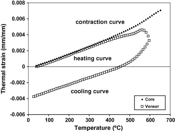
Contraction behavior for each ceramic was measured in a single push-rod dilatometer (Model 1000R, Orton, Westerville, OH) using a rectangular specimen with dimensions of 5 mm by 5 mm by 25.4 mm. A force of 1.96 N was applied to the flat-end pushrod to maintain specimen contact. Each specimen was ground to ensure that both ends were parallel. The dilatometer was calibrated using a NIST platinum standard at a heating rate of 3°C/min. A K-type thermocouple was in contact with each specimen to register the thermal history during each run. Each specimen was heated at a rate of 3°C/min until creep occurred at a specified expansion limit, followed by convective cooling in the furnace (furnace power terminated). Temperature and expansion/contraction data were recorded at one degree intervals. The coefficients of thermal contraction were calculated on the cooling curve only. Typical heating/cooling curves are shown in Fig. 1 for E2C core ceramic and E2V veneering ceramic. Only the contraction curve for the core material is shown since the heating and cooling curves nearly coincide. Note that the cooling curve for the veneer is displaced from the heating curve due to creep that occurs at about 540 °C. Also note the change in slope of the veneer’s heating curve at about 480 °C which is commonly called “relaxation of excess volume”. Because of this effect, expansion values from first run heating curves are unreliable and contraction values are generally preferred [8]. Moreover, it makes more sense to use the contraction curve since residual stresses in dental prostheses develop as the prostheses cool from the firing temperature.
Fig. 1.
Expansion/contraction curves for E2C core and E2V veneering ceramics.
Viscoelastic finite element analysis
The constitutive theory for the two-dimensional viscoelastic element (VISCO88) in the ANSYS finite element program (ANSYS, Inc, Canonsburg, PA) is based on stress and structural relaxation theory [9, 10, 11, 12]. The viscoelastic option of the ANSYS program has been used previously to study the effects of cooling rate, including tempering, on the stress development in metal-ceramic disks [13]. Details of the theoretical development of viscoelasticity in the ANSYS program are available in the theoretical manual. Of special interest is the form of the free thermal strain for elastic behavior given by
| (1) |
and in the viscoelastic material by
| (2) |
where αe is the thermal contraction coefficient in the elastic state, αL is the thermal contraction coefficient in the liquid state, Tf is the fictive temperature [12], and To is the initial temperature. The thermal contraction coefficients are assumed to be equilibrium values and the effects of cooling rates are included through the fictive temperature which is cooling rate dependent.
Regression techniques were used to fit polynomials to the thermal strain versus temperature curve in the elastic range (usually 500-25 °C) and the liquid range (above 500 °C). The coefficients of thermal contraction are determined from the derivative of the regression polynomials. The contraction coefficients can be represented by:
| (3) |
where αe and αL are the elastic and liquid coefficients of contraction, respectively, T is the temperature (°C), and the “a” values are the regression coefficients given in Table 2. The R2 values for the regression fits are included in Table 2 and range from 0.9945 to 0.9999. The efficacy of viscoelastic finite element simulation of the contraction behavior of a dental ceramic measured in a dilatometer has been demonstrated in a previous publication [14].
Table 2.
Regression coefficients for thermal contraction coefficients.
| Materials | αe (mm/mm·°C) | αL (mm/mm·°C) | 500α25 (mm/mm·°C) | ||||||
|---|---|---|---|---|---|---|---|---|---|
| a0 (1/°C) 10−6 | a1(1/°C)2 10−8 | a2(1/°C)3 10−11 | R2 | a0 (1/°C) 10−6 | a1(1/°C)2 10−8 | a2(1/°C)3 10−11 | R2 | 10−6 | |
| Empress 2® core | 10.614 | −1.519 | 4.035 | 0.9999 | NA | NA | NA | NA | 10.18 |
| Experimental core | 9.709 | −66.228 | 2.830 | 0.9999 | NA | NA | NA | NA | 10.40 |
| Empress 2® veneer | 10.751 | −2.421 | 5.727 | 0.9995 | −39.118 | 11.530 | 0.0 | 0.9999 | 9.38 |
| Eris® veneer | 9.057 | −0.115 | 1.209 | 0.9997 | −65.105 | −18.091 | 0.0 | 0.9999 | 10.79 |
| Vita VMK68 body | 8.913 | 1.053 | 0.0 | 0.9991 | −14.214 | 6.303 | 0.0 | 0.9945 | 11.66 |
| Finesse body | 15.401 | −5.438 | 13.379 | 0.9976 | −87.040 | 24.760 | 0.0 | 0.9999 | 13.78 |
Specimen Fabrication
Spheres
The core-ceramic spheres (6.3 mm diameter) were pressed using the conventional lost-wax method. In this case, acrylic spheres with wax sprues and stems were assembled. A mold was designed and used to ensure that each pattern was constructed with a consistent size and angle. The core-ceramic patterns were fabricated, invested, burned out and hot pressed. The processing of the core ceramics was in accordance with the manufacturer’s recommendations. The core ceramic sphere specimens were divested and cleaned. Each completed core ceramic sphere had a protruding stem that measured ~1 mm diameter × ~5 mm in length to facilitate handling during specimen fabrication.
After pressing, the two spherical core materials (n=48) were randomly divided into four groups (n=6 per group). A thin coating (~0.25 mm) of the designated veneer was applied to each spherical core specimen and fired at the required temperature for each veneering porcelain. After the first 0.25 mm veneer firing, the spheres were then coated with the remainder of a 1.8-mm-thick layer of the veneering ceramic, producing a 10-mm-diameter sphere. Upon application of the veneering ceramic, the stem was inserted into a square of insulation material (Thermoz, American Dental Supply Inc., Easton, PA.) on a honeycomb sagger tray (National Keystone Products CO., Cherry Hill, NJ) to stabilize the sphere during firing. Each veneered specimen was fired individually in a programmable furnace (Vista Wizard Jelrus, Jelrus International, Hicksville, NY). The furnace has a mobile platform that elevates into the chamber and lowers post firing. Therefore, the specimens were quickly exposed to ambient air, followed by free convective cooling in ambient air to reach room temperature (bench cooling). The veneer applications received two heat treatments.
Cylinders
Open-ended cylindrical forms (9 mm high, 11 mm inner diameter) were cast in wax. There were three different sets of core cylinders with wall thicknesses of 0.5 mm, 0.8 mm, and 1.1 mm. The core ceramics were hot pressed per the manufacturer’s recommendation using the cylindrical wax patterns (n=72). The hollow core ceramic cylinder specimens were divested and cleaned according to the manufacturer’s instructions. Then the core specimens were randomly divided into four experimental groups according to wall thickness (n=3 per thickness, per veneer). The first thin coating (~0.25 mm) of the designated veneer was applied to the exterior of each cylindrical core specimen and fired. Each veneering layer was fired at its specified temperature. After the cylinders were completely veneered, every specimen had a total wall thickness of 2 mm (core and veneer combined). Each veneered specimen was fired individually in a programmable furnace (Vista Wizard Jelrus, Jelrus International, Hicksville, NY). The cooling procedure was similar to that described above for the spheres. The veneer coatings were fired twice.
Material properties
The core materials were assumed to behave elastically during cooling while the veneer ceramics exhibited time-dependent viscoelastic behavior. The three-dimensional stress-strain relationships for a linear isotropic viscoelastic material are given by:
| (4) |
where σij is the Cauchy stress tensor, eij is the deviatoric strain tensor, δij is the Kronecker delta, G(t) is the shear relaxation function, K(t) is the bulk relaxation function, θ(t) is the volumetric strain, t is the present time, and τ is the past time. It has been shown [15] that the shear relaxation function for the veneering ceramics can be characterized by a four-term Prony series represented in the form:
| (5) |
where G0 = G(0) is the initial shear modulus, λi is the shear relaxation time (i=1,2,3,4) and .
It is known that dilatational relaxation has a minor effect on stress calculations for most stress states [16]. Therefore, the dilatational behavior of the dental ceramics has been assumed to be elastic. Thus,
| (6) |
The stress relaxation coefficients were determined from creep data measured in a beam bending viscometer (BBV) following the procedures described by DeHoff and Anusavice [15]. The elastic and thermal properties of the materials used in this study are presented in Table 3 while the viscoelastic properties are given in Table 4.
Table 3.
Elastic and thermal properties of the dental ceramics.
| Dental ceramics | Modulus (GPa) | Poisson’s ratio | Density (kg/mm3) | Specific heat J/kg·K) | Conductivity (W/mm·K |
|---|---|---|---|---|---|
| Empress 2® core1 | 96 | 0.24 | 2.514E-6 | 734 | 4.03E-3 |
| Experimental core1 | 86 | 0.27 | 2.567E-6 | 711 | 5.35E-3 |
| Empress 2® veneer | 65 | 0.26 | 2.531E-6 | 734 | 1.01E-2 |
| Eris® veneer1 | 68 | 0.24 | 2.640E-6 | 711 | 2.40E-2 |
| Vita VMK68 body2 | 69 | 0.22 | 2.4E-6 | 700 | 1.05E-3 |
| Finesse body | 773 | 0.243 | 3.11E-63 | 7004 | 1.05E-34 |
Values from DeHoff and Anusavice [14]
Values from Biomaterials Properties Database, University of Michigan
Elastic properties measured at the University of Florida
Thermal values assumed equal to feldspathic porcelain
Table 4.
Viscoelastic properties at a reference temperature of 700°C for the veneering dental ceramics.
| Ceramic | G0 (MPa) | K0 (MPa) | C1 | C2 | C3 | C4 | λ1 (s) | λ2 (s) | λ3 (s) | λ4 (s) |
|---|---|---|---|---|---|---|---|---|---|---|
| IPS Empress 2® | 23800 | 35900 | 0.9971 | 0.0015 | 0.0012 | 0.0002 | 1.450E-3 | 2.000E-3 | 4.000E-3 | 6.000E-3 |
| IPS Eris™ | 27400 | 43600 | 0.9980 | 0.0005 | 0.0002 | 0.0013 | 7.490E-6 | 5.560E-6 | 1.640E-5 | 3.200E-4 |
| Vita VMK68 | 28400 | 41300 | 0.9960 | 0.0030 | 0.0006 | 0.0004 | 1.316E-2 | 1.000E-1 | 5.000E-3 | 3.000E-3 |
| Finesse | 31100 | 49400 | 0.9990 | 0.0004 | 0.0004 | 0.0002 | 3.456E-5 | 7.143E-4 | 8.065E-4 | 8.772E-4 |
Finite element models
The cylinders and spheres were modeled with 8-node axisymmetric thermal (SOLID77) and viscoelastic (VISCO88) elements. Because of symmetry, only half the height of the cylinder and a quarter of the sphere were modeled. The number of elements and nodes used for the cylinder for each case varied depending on the core thickness. For the spheres, 190 elements and 546 nodes were used. Shown in Fig. 2 is the finite element model of the cylinder with a core thickness of 0.8 mm, while the model for the sphere is shown in Fig. 3. Although the analyses are essentially two dimensional (axisymmetric), for illustrative purposes the finite element model is shown rotated through 270° for the cylinder and 90° for the sphere. The analyses required a transient heat transfer run for each combination to determine input temperatures for the structural model. The thermal element was used to simulate free convective cooling of the cylinder from an initial temperature of 700 °C to room temperature. Because stress relaxation is quite rapid at high temperatures, the initial temperature of 700 °C, rather than the actual sintering or pressing temperatures, was chosen to reduce the number of calculations. A constant convective heat transfer coefficient equal to 1.7031E-5 W/mm2·K was applied to the exposed surfaces to provide an initial cooling rate at the surface of each specimen of approximately 640 °C/min, which simulates typical bench cooling of dental prostheses. This value for the convective coefficient was selected based on thermocouple data reported by Anusavice et al. [5] for cooling of bilayer ceramic disks from the firing temperature. Nodal temperatures were calculated at a specific number of time steps and these temperatures served as the input to the structural model using the viscoelastic element. The structural model was used to analyze transient and residual stresses for each of the specimens.
Fig. 2.
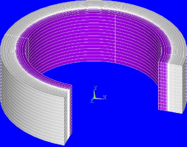
Finite element model of the cylinder with 0.8 mm thick core and 1 mm thick veneer. Elements are shown rotated through 270°.
Fig. 3.
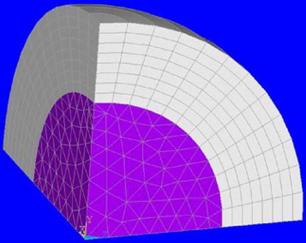
Finite element model of the sphere. Elements are shown rotated through 90°.
Results
Experimental
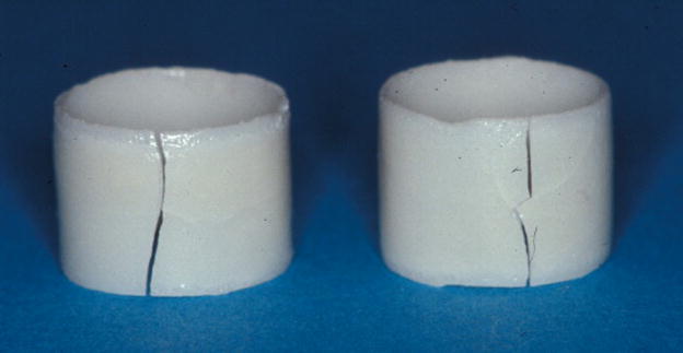
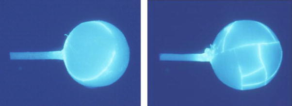
After individual fabrication (pressing, veneering, firing and bench cooling) each specimen was examined visually for cracks, followed by fiberoptic transillumination to search for any cracks possibly not observed under room light in the first inspection. Specimens from each geometric and material configuration for each treatment group were immersed in a fluorescing dye solution and photographed under black light. The observed cracks occurred within the first 5-min of bench cooling and there were no delayed failures after the initial 5-min cooling time. None of the E2C/E2V (Δα = +0.8 ppm/K), E2C/ERV (Δα = −0.61 ppm/K), EXC/E2V (Δα = +1.02 ppm/K), or EXC/ERV (Δα = −0.39 ppm/K) cylinders showed any evidence of cracking while 100% of the E2C/VV (Δα = −1.48 ppm/K), E2C/FV (Δα = −3.01 ppm/K), EXC/VV (Δα = −1.26 ppm/K), and EXC/FV (Δα = −2.79 ppm/K) cylinders failed, either at the wash coat firing stage or after the final firing. For the spherical geometry, 16% of the E2C/E2V specimens failed while none of the EXC/E2V, E2C/ERV, or EXC/ERV specimens showed evidence of cracking. All spheres veneered with Vita or Finesse ceramics failed with E2C or EXC, either at the wash coat stage or after final firing. Crack patterns of failed cylinders and spheres are shown in Fig. 4 and Fig. 5, respectively. Crack patterns in the cylinders and spheres suggest that failure occurred primarily because of hoop stresses. For the sphere, the tangential stresses are essentially the same in all directions and, therefore, the cracks shown in Fig. 5 are consistent with failure caused by tangential stresses. The calculated stresses in the cylinders and spheres are maximum at the interface whereas the cracks shown in Figs. 4 and 5 are at the surface. However, we have not determined where the cracks originated so it is possible that first cracking occurred at the interface. The observed cracks occurred within the first 5-min of bench cooling and all cracks in the veneer constituted a failed specimen. There were no ‘delayed failures’, i.e., after the initial 5-min cooling time.
Fig. 4.
Failed 0.8 mm E2C core cylinders with FV veneer (left) and VV veneer (right).
Fig. 5.
Failed E2C core spheres with VV body (left) and FV veneer (right).
Finite element calculations
Finite element stress results are available throughout each model at each of the time increments. However the maximum residual stresses and the maximum transient stresses developed during cooling are of primary interest. Shown in Fig. 6 is a plot of the residual hoop stresses (Sz) for the upper half of a cylinder composed of 0.8-mm-thick E2C core veneered with a 1.2-mm-thick layer of Vita porcelain. We expect failure to occur when the maximum principal tensile stress reaches the tensile strength of each specimen. The mean strength of feldspathic porcelain is approximately 60 MPa in the absence of flaws. For the cylinders the hoop stress component is generally equal to the maximum principal stress. Note that the maximum tensile stress of 77 MPa occurs in the veneer layer within the interface area near the top edge. We would expect a crack to initiate at this point and then propagate down the interface to form a longitudinal crack which would then proceed to the surface. Initially, the residual stresses in the core material are primarily compressive; however, when the veneer layer cracks, it changes the stress pattern in the core so that high tensile stresses sufficient to cause failure of the core can develop. The crack patterns shown in Fig. 4 are consistent with this scenario for the E2C/VV and E2C/FV cases since the longitudinal cracks caused complete separation of core and veneer.
Fig. 6.
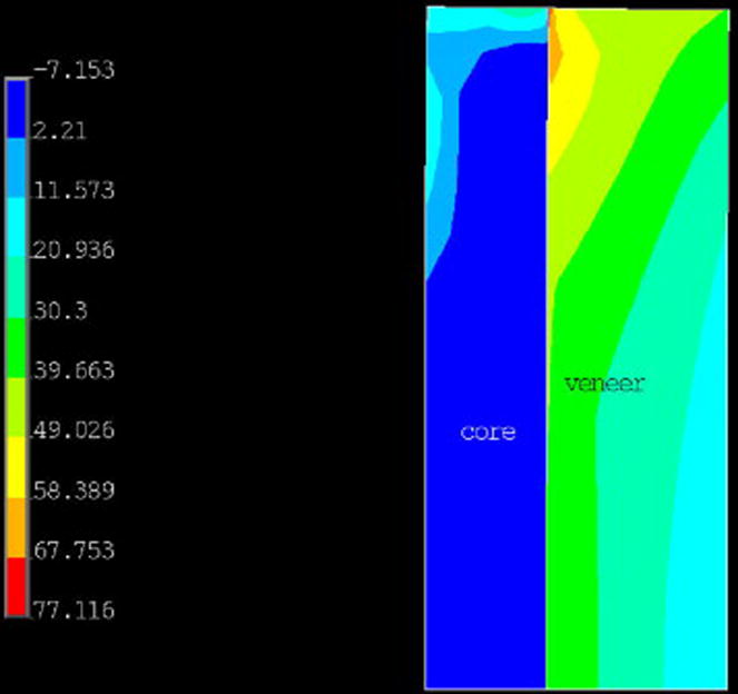
Plot of residual hoop stresses (MPa) in the E2C/VV cylinder composed of a 0.8-mm-thick core with a 1.2-mm-thick veneer layer. Tensile stresses are indicated as positive.
Shown in Fig. 7 is a plot of residual hoop stresses for a quarter section of the sphere composed of the solid E2C core with Vita veneer. The maximum tensile stress of 45 MPa occurs in the veneer adjacent to the core/veneer interface. For the sphere, the tangential stress components (hoop stress) are the same in all directions so a crack could form in any direction, depending on the presence of any flaws. The crack patterns shown in Fig. 5 for the E2C/VV and E2C/FV spheres are consistent with symmetric stress patterns. Again, we expect cracks to initiate at the interface and propagate to the surface. The stresses in the core material are initially compressive, and then, tensile stresses develop after the veneer fails, but there is no evidence that the core cracked in these cases.
Fig. 7.
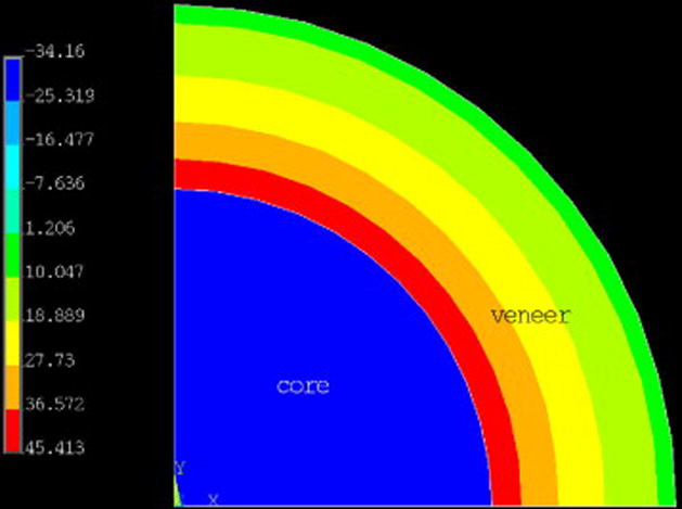
Plot of residual (hoop) stresses (MPa) in the E2C/VV sphere. Tensile stresses are indicated as positive.
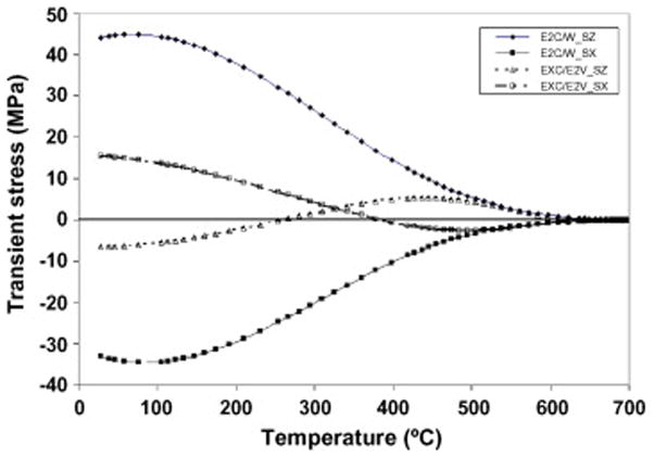
As indicated previously, cracking of the specimens occurred within the first 5 min of the bench cooling process, which suggests that transient stresses are higher than the residual values. Finite element calculations confirm this fact as shown in Fig. 8 which is a plot of hoop stress (SZ) and radial stress (SX) components during the cooling process. This plot is for the E2C/VV and EXC/E2V spheres and it shows that transient stresses (SZ) for the EXC/E2V case peak at approximately 75 °C (4 min into simulated bench cooling), but the values are only slightly higher than the residual values. Note that for the E2C/VV case, the tensile stress components (SZ) are associated with compressive radial stresses (SX). This agrees with the common understanding that in a sphere or cylinder, a negative mismatch (αc < αv) leads to tensile hoop stresses and compressive radial stresses in the veneer layer while the opposite is true for αc > αv, as is the case for EXC/E2V.
Fig. 8.
Transient stress versus temperature in the veneer layer at the core/veneer interface for the sphere. SZ is the hoop stress component and SX is the radial stress component.
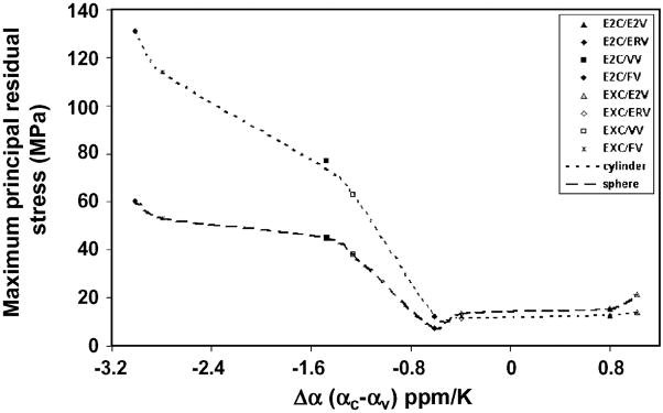
Shown in Fig. 9 is a plot of the maximum principal stress (S1) in the veneer layer at the interface as a function of thermal contraction mismatch (Δα) for both geometries. Note that the stress magnitudes are relatively constant for Δα’s ranging from −0.61 ppm/K to +1.02 ppm/K and then increase rapidly for Δα’s less than −0.61 ppm/K. Also note that the stresses in the cylinder are greater than those in the sphere for Δα’s less than −0.61 ppm/K. This is the result of a stress concentration effect at the ends of the cylinder that is not present in the sphere. The stresses in the cylinder away from the edges are well below the maximum values (see Figs. 6&7) and more nearly equal to those in the sphere.
Fig. 9.
Maximum principal residual stress in the veneer layer adjacent to the interface for the 0.8-mm-thick core cylinder and sphere for each of the veneering ceramics.
The finite element stresses for all geometries are presented in Table 5. Note that the calculated residual tensile stresses are below 22 MPa for the compatible systems E2C/E2V, EXC/E2V, E2C/ERV, EXC/ERV) and greater than 38 MPa for the incompatible systems (E2C/VV, EXC/VV, E2C/FV, EXC/FV). If we assume that the failure strengths for the veneering ceramics are on the order of 60 MPa, then the calculated values are in agreement with the experimental results. We expect that the presence of flaws and a wet environment would reduce the effective failure strength and would lead to variability in failure data. Also note that high stresses were calculated for the incompatible systems at the end of the wash coat, which also agrees with the experimental evidence.
Table 5.
Calculated residual tensile stresses (MPa) in the veneer layer for bilayer cylinders and spheres.
| Cylinder | E2C/E2V | EXC/E2V | E2C/ERV | EXC/ERV | E2C/VV | EXC/VV | E2C/FV | EXC/FV | E2C/VV | E2C/FV |
|---|---|---|---|---|---|---|---|---|---|---|
| Core layer | Δα = +0.8 | Δα = +1.02 | Δα = −0.61 | Δα = −0.39 | Δα = −1.48 | Δα = −1.26 | Δα = −3.01 | Δα = −2.79 | WC* | WC* |
| 0.5 mm | 12.3 | 14.9 | 10.3 | 11.4 | 61 | 50 | 128 | 90 | 81 | 128 |
| 0.8 mm | 12.5 | 14.0 | 12.2 | 11.6 | 77 | 63 | 131 | 114 | 83 | 132 |
| 1.1 mm | 8.8 | 9.7 | 10.3 | 8.9 | 83 | 68 | 133 | 116 | 80 | 124 |
|
| ||||||||||
| Sphere | 15.5 | 21.3 | 7.3 | 13.3 | 45 | 38 | 60 | 53 | NA | NA |
Cylindrical specimens that failed after the wash coat (WC) firings (0.25mm thick) did not receive further treatment. Δα values are given in units of ppm/K.
Discussion
Although the finite element and experimental results of this study suggest that a “safe” thermal contraction mismatch (Δα) lies in the range −0.61 ppm/K to +1.02 ppm/K, there are a number of factors to consider. The contraction mismatch values represented only eight distinct combinations so significant gaps in experimental data exist. Each ceramic has its specific elastic, thermal, and viscoelastic properties, along with a particular thermal contraction pattern. There is the usual scatter in data for each property and there is the possibility of batch-to-batch variation. In terms of finite element modeling, the calculations are only as good as the input data and the simulation of the physical situation. For example, the thermal analysis assumed a rotationally symmetric cooling pattern while the actual bench cooling could have induced some asymmetrical thermal gradients. The structural finite element model assumed perfect coupling at the core/veneer interface, which is distinct in the model and most likely “fuzzy” in the actual specimens. In spite of the limitations, the finite element results do tend to confirm the experimental results.
While it would be beneficial if the results of this study suggested that compatible all-ceramic systems could be identified with certainty on the basis of a limiting value for the thermal contraction mismatch between core and veneer, this is not the case. The eventual clinical success or failure of a ceramic combination depends on many factors including strength, fracture toughness, contraction mismatch, stress corrosion susceptibility, geometry, fabrication techniques, relaxation behavior, glass transition temperatures, and the magnitude and orientation of occlusal loads. However, we can state with some confidence that severely mismatched combinations such as VV and FV with any low expansion core (Δα < −1.2 ppm/K) should lead to clinical failure of single crowns or fixed dental prostheses. Such incompatible combinations can be identified with simple geometries such as the cylinders or spheres. However, for more closely matched systems, it seems unlikely that the simple screening geometries can reliably predict success or failure in clinical situations. This is especially true when one considers that manufacturers report average thermal expansion/contraction values with a standard deviation as large as ±0.5 ppm/K so that nominally compatible systems could become incompatible at the extremes of the values.
Conclusions
Simple geometries such as the cylinder, which simulates a crown, and the sphere, which simulates a pontic, can be used to screen out highly incompatible ceramic-ceramic systems but they cannot be used to establish a “safe” mismatch value. Viscoelasic finite element analyses can prove useful for identifying the effects on transient and residual stress of factors such as cooling rates, geometry, and material properties. Because of these interacting factors, manufacturers should be cautious in recommending all-ceramic prostheses for potentially high-stress situations.
Acknowledgments
This study was supported by NIH-NIDCR Grant No. DE06672 and the Mechanical Engineering Department at UNC Charlotte. The ceramic materials were provided by Ivoclar Vivadent (Amherst, NY), Vident (Brea, CA), and DENTSPLY Ceramco (Burlington, NJ).
Footnotes
Publisher's Disclaimer: This is a PDF file of an unedited manuscript that has been accepted for publication. As a service to our customers we are providing this early version of the manuscript. The manuscript will undergo copyediting, typesetting, and review of the resulting proof before it is published in its final citable form. Please note that during the production process errors may be discovered which could affect the content, and all legal disclaimers that apply to the journal pertain.
References
- 1.Walton TR, O’Brien WJ. Thermal stress failure of ceramic bonded to a palladium silver alloy. J Dent Res. 1985;64:476–480. doi: 10.1177/00220345850640031801. [DOI] [PubMed] [Google Scholar]
- 2.Anusavice KJ, DeHoff PH, Gray A, Lee RB. Delayed crack development in ceramic due to incompatibility stress. J Dent Res. 1988;67:1086–1091. doi: 10.1177/00220345880670080501. [DOI] [PubMed] [Google Scholar]
- 3.Anusavice KJ, Gray AE. Influence of framework design, contraction mismatch, and thermal history on ceramic checking in fixed partial dentures. Dent Mater. 1989;5:58–63. doi: 10.1016/0109-5641(89)90095-x. [DOI] [PubMed] [Google Scholar]
- 4.Steiner PJ, Kelly JR, Giuseppetti AA. Compatibility of ceramic-ceramic systems for fixed prosthodontics. 1997. Int J Prosthodont. 1997;4:375–380. [PubMed] [Google Scholar]
- 5.Anusavice KJ, DeHoff PH, Hojjatie B, Gray A. Influence of tempering and contraction mismatch on crack development in ceramic surfaces. J Dent Res. 1989;68:1182–1187. doi: 10.1177/00220345890680070801. [DOI] [PubMed] [Google Scholar]
- 6.Mora GP, O’Brien WJ. Thermal shock resistance of core reinforced all-ceramic crown systems. J Biomed Mater Res. 1994;28:189–194. doi: 10.1002/jbm.820280208. [DOI] [PubMed] [Google Scholar]
- 7.Isgro G, Wang H, Kleverlaan CJ, Feilzer AJ. The effects of thermal mismatch and fabrication procedures on the deflection of layered all-ceramic discs. Dent Mater. 2005;21:649–655. doi: 10.1016/j.dental.2004.09.001. [DOI] [PubMed] [Google Scholar]
- 8.Fairhurst CW, Anusavice KJ, Hashinger DT, Ringle RD, Twiggs SW. Thermal expansion of dental alloys and porcelains. J Biomed Mater Res. 1980;14:435–446. doi: 10.1002/jbm.820140410. [DOI] [PubMed] [Google Scholar]
- 9.Narayanaswamy OS. Stress and structural relaxation in tempering glass. J Am Ceram Soc. 1978;161:146–152. [Google Scholar]
- 10.Scherer GW, Rekhson SM. Viscoelastic-elastic composites: I, general theory. J Am Ceram Soc. 1982;65:352–360. [Google Scholar]
- 11.Zienkiewicz OC, Watson M, King IP. A numerical method of viscoelastic stress analysis. Int J Mech Sci. 1968;10:807–827. [Google Scholar]
- 12.Markovsky A, Soules TF. An efficient and stable algorithm for calculating fictive temperatures. J Am Ceram Soc. 1984;67:C56–57. [Google Scholar]
- 13.DeHoff PH, Anusavice KJ, Vontivillu SB. Analysis of tempering stresses in metal-ceramic disks. J Dent Res. 1996;75:743–751. doi: 10.1177/00220345960750020301. [DOI] [PubMed] [Google Scholar]
- 14.DeHoff PH, Anusavice KJ, Götzen N. Viscoelastic finite element analysis of an all-ceramic fixed partial denture. J Biomech. 2006;39:40–48. doi: 10.1016/j.jbiomech.2004.11.007. [DOI] [PubMed] [Google Scholar]
- 15.DeHoff PH, Anusavice KJ. Shear stress relaxation of dental ceramics based on creep behavior. Dent Mater. 2004;20:717–725. doi: 10.1016/j.dental.2003.10.005. [DOI] [PubMed] [Google Scholar]
- 16.Scherer GW. Relaxation in glass and composites. New York: John Wiley and Sons, Inc; 1986. p. 87. [Google Scholar]


