Abstract
Purpose: To compare the performance of equivalently sized radiofrequency and microwave ablation applicators in a normal porcine lung model.
Materials and Methods: All experiments were approved by an institutional animal care and use committee. A total of 18 ablations were performed in vivo in normal porcine lungs. By using computed tomographic (CT) fluoroscopic guidance, a 17-gauge cooled triaxial microwave antenna (n = 9) and a 17-gauge cooled radiofrequency (RF) electrode (n = 9) were placed percutaneously. Ablations were performed for 10 minutes by using either 125 W of microwave power or 200 W of RF power delivered with an impedance-based pulsing algorithm. CT images were acquired every minute during ablation to monitor growth. Animals were sacrificed after the procedure. Ablation zones were then excised and sectioned transverse to the applicator in 5-mm increments. Minimum and maximum diameter, cross-sectional area, length, and circularity were measured from gross specimens and CT images. Comparisons of each measurement were performed by using a mixed-effects model; P < .05 was considered to indicate a significant difference.
Results: Mean diameter (3.32 cm ± 0.19 [standard deviation] vs 2.70 cm ± 0.23, P < .001) was 25% larger with microwave ablation and mean cross-sectional area (8.25 cm2 ± 0.92 vs 5.45 cm2 ± 1.14, P < .001) was 50% larger with microwave ablation, compared with RF ablation. With microwave ablation, the zones of ablation were also significantly more circular in cross section (mean circularity, 0.90 ± 0.06 vs 0.82 ± 0.09; P < .05). One small pneumothorax was noted during RF ablation but stabilized without intervention.
Conclusion: Microwave ablation with a 17-gauge high-power triaxial antenna creates larger and more circular zones of ablation than does a similarly sized RF applicator in a preclinical animal model. Microwave ablation may be a more effective treatment of lung tumors.
© RSNA, 2009
Thermal ablation is becoming an increasingly attractive choice for the treatment of unresectable tumors in the lung, both as a primary treatment strategy and as an adjuvant to external radiation (1–3). To date, radiofrequency (RF) energy has seen the most utility worldwide for pulmonary ablation. However, there are significant technical deficiencies in the delivery of RF energy to the lung that have reduced enthusiasm for this technique. Inflated lung tissue creates a high-impedance path for RF current flow that can be several times greater than the impedance encountered in normal liver, even when considering a solid tumor embedded in the lung (4–6). Higher impedance reduces energy deposition from current RF generators, which, in turn, leads to a smaller temperature increase and potentially increased treatment failure rates (7). In particular, the lack of heating in the lung may prevent ablation of satellite tumor deposits just beyond the periphery of the targeted tumor (8,9). The inherently high impedance of normal lung is exacerbated by other fundamental limitations in RF ablation, such as an inability to heat charred or desiccated tissue or overcome even moderate heat sinks (eg, vessels larger than 3 mm in diameter) (10,11). The use of multiprong electrodes, which increase total electrode surface area, and ionic fluid infusion have been shown to decrease impedance to RF current flow in the lung (2,5,6). Although effective, these techniques are not without drawbacks. Fluid infusion is unpredictable and has been associated with an increased risk of complications (12). Multitined electrodes increase invasiveness, can be difficult to use in solid tumors situated in normal lung tissue, and have been associated with irregular zones of ablation and increased rates of occurrence of pneumothorax (2,13,14).
Microwave energy penetration is not limited by the lower electrical permittivity and conductivity of inflated lung, desiccated tissue, or charred tissue (4). Unlike RF electrodes, microwave antennas do not require the placement of grounding pads, and multiple antennas can be operated simultaneously in close proximity without switching (15–17). In addition to the demonstrated advantages of microwave ablation compared with RF ablation for treatment of tumors in the liver, recent preclinical and clinical studies have shown that microwaves can be effective for pulmonary ablation of tumors there (18–24). However, to our knowledge, no comparison between microwave ablation and RF ablation has been performed in a relevant preclinical lung model. Thus, the purpose of this study was to compare the performance of equivalently sized RF and microwave ablation applicators in a normal porcine lung model.
MATERIALS AND METHODS
All studies in animals were performed with approval from the Animal Care and Use Committee of our institution and in accordance with the Guide for Care and Use of Laboratory Animals issued by the National Research Council (25).
In Vivo Experimental Procedure
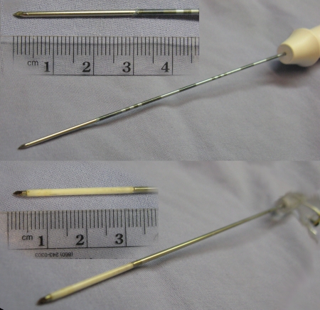
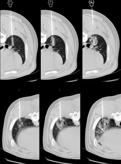
Three female domestic swine (University of Wisconsin Agricultural Research Station, Arlington, Wis) with a mean weight of 65 kg (range, 60–70 kg) were used for this study. Prior to administration of the anesthetic, sedation was achieved with 7 mg/kg of intramuscularly administered tiletamine hydrochloride and zolazepam hydrochloride (Telazol; Wyeth, Fort Dodge, Iowa) and 2.2 mg/kg of xylazine hydrochloride (Xyla-Ject; Phoenix Pharmaceutical, St Joseph, Mo). Endotracheal intubation was performed in the standard fashion, facilitated by means of 0.05 mg/kg atropine (Phoenix Pharmaceutical). Anesthesia was then induced and maintained with 2% inhaled isoflurane (Halocarbon Laboratories, River Edge, NJ) to effect. Once anesthetized, animals were placed prone on the bed of a computed tomographic (CT) scanner (LightSpeed Plus; General Electric, Waukesha, Wis). RF and microwave ablation applicators were placed in peripheral aspects of the porcine lungs by using CT fluoroscopic guidance with the same scanner. Applicators were placed to ensure no overlap of ablation zones and to prevent heat sinks, such as large vessels, that might skew the results. Three applicators of each energy type were used in each animal, for a total of six ablations per animal (Fig 1). The placement, location, and order of application were varied to balance the study groups on the basis of treatment of the right or the left lung and the lobe location.
Figure 1:
Two applicators used for RF ablation at top and two used for microwave ablation at bottom. RF and microwave applicators were 17 gauge (1.5-mm diameter).
RF (n = 9) and microwave (n = 9) ablations were performed in the lung parenchyma during normal ventilation. RF energy was delivered through a 17-gauge internally cooled electrode (Cool-tip; Valleylab, Boulder, Colo) with 3-cm active length powered by a 200-W (maximum) generator with impedance-based pulsing. The high-power microwave ablation system consisted of a prototypic 17-gauge water-cooled triaxial antenna delivering power from a 2.45-GHz generator with 125-W output (Cober Muegge, Norwalk, Conn) (26,27). Power was transferred from the generator to the antenna through 1.5-m-long coaxial cables (RG-400; Pasternack Enterprises, Irvine, Calif), resulting in a theoretical power delivery at the antenna tip of approximately 70 W. The treatment duration was 10 minutes for both RF and microwave ablations and was the only treatment end point. The cooling-water flow rate was approximately 100 mL/min in both systems. During each ablation, CT fluoroscopic images were acquired at 1-minute intervals to monitor ablation zone growth. After all ablations were complete, animals were sacrificed by using an intravenous injection of 0.2 mL/kg of 390 mg/mL of pentobarbital sodium and 50 mg/mL of phenytoin sodium (Beuthanasia-D; Schering-Plough, Kenilworth, NJ), and the lungs were removed en bloc.
Measurement Details
Ablation zones were sliced transverse to the electrode insertion track in approximately 5-mm increments. Slices were placed on a flatbed scanner, and digital images were saved electronically. Measurements of minimum diameter, maximum diameter, cross-sectional area, and isoperimetric ratio of the gross ablation zones, on the basis of the outer edge of the transition zone, were then performed by two observers (C.L.B., P.F.L., each with 4 years of experience) with software (ImageJ, version 1.39e; National Institutes of Health, Bethesda, Md) (19). The isoperimetric ratio, calculated as 4π · A/Pe2, where A is area and Pe is perimeter, is a measure of the circularity of a two-dimensional object, where values near unity represent more circular shapes and values approaching zero represent oblate or cleft shapes. Initial impedances and final tip temperatures after RF ablations and the power reflection coefficient (calculated as RP/IP, where RP is reflected power and IP is input power) during microwave ablations were also recorded. Temperatures inside the ablation zone could not be measured with the prototypic antenna.
Ablation lengths and diameters were also measured from intraprocedural CT images on the basis of the area of ground-glass opacity (28,29). These measurements were used to estimate the ablation volume by using an ellipsoid assumption, calculated as π · L · D2/6, where L is length and D is diameter. An aspect ratio of the imaging measurements was also calculated, with D/L, and was compared between RF and microwave ablation. Intraprocedural CT images also were analyzed to identify any pertinent details in appearance or to identify unintended thermal damage.
Statistical Analysis
Descriptive statistics were calculated for each measurement. Comparisons between ablation zones created by using RF and those created by using microwave energy also were performed for each measurement by using a linear mixed-effects model, with animals modeled as random effects because multiple observations were obtained in each animal. Because the study size was relatively small, we did not use a correlation structure in the model but rather assumed that intraanimal errors were independent. Statistical analysis was performed by using an open-source statistical package (R, version 2.7.1; R Foundation for Statistical Computing, Vienna, Austria; www.r-project.org). P values of less than .05 were considered to indicate a significant difference.
RESULTS
All animals tolerated the procedures without major complications. One small pneumothorax was observed in one animal after the first RF ablation was performed in that animal, but stabilization was achieved without intervention. No other major complications were noted.
Ablation Zone Measurements
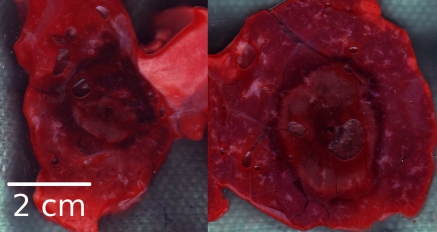
At gross pathologic analysis, ablation zones achieved with microwave ablation were 25% larger in mean diameter (3.32 cm ± 0.19 [standard deviation] vs 2.70 cm ± 0.23, P < .001) and 50% larger in cross-sectional area (8.25 cm2 ± 0.92 vs 5.45 cm2 ± 1.14, P < .001) when they were compared with ablation zones achieved with RF ablation (Table 1, Fig 2). Ablation zones achieved with microwave ablation were significantly more circular in cross section than ablation zones achieved with RF ablation (mean isoperimetric ratio, 0.90 ± 0.06 vs 0.82 ± 0.09; P = .03). For gross measurements, the standard deviations for microwave ablation were also slightly lower than those for RF ablation.
Table 1.
Measurements of Gross RF and Microwave Ablation Specimens
Note.—Nine samples each were obtained for RF ablation and microwave ablation.
Data are the mean ± standard deviation.
Figure 2:
Cross sections at gross pathologic analysis. Left: RF ablation. Right: Microwave ablation. Microwave ablation zones were generally larger and more circular in cross section and typically contained sharper transition between ablation zone and surrounding lung parenchyma. Samples from both RF and microwave ablation contained hemorrhage in parenchyma adjacent to ablation zone.
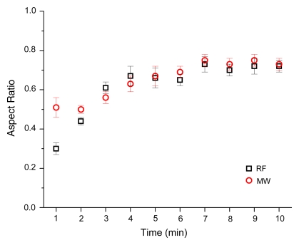
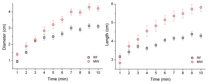
Imaging assessment of ablation zone size and shape was confounded by the appearance of local hemorrhage peripheral to the ablation zone. On CT images, ablation zones achieved with microwave ablation were longer (mean, 5.82 cm ± 0.66 vs 4.29 cm ± 0.38; P < .001) and larger in mean diameter (4.21 cm ± 0.56 vs 3.11 cm ± 0.40, P < .001) than ablation zones achieved with RF ablation (Table 2). Therefore, ablation zones achieved with microwave ablation were 133% larger in volume than those achieved with RF ablation (mean, 32.46 cm3 ± 5.22 vs 13.92 cm3 ± 5.72; P < .001). There was no significant difference between aspect ratios calculated for microwave or RF ablation after 10 minutes (mean, 0.73 ± 0.09 vs 0.72 ± 0.08; P > .99), although ablation zones achieved with RF ablation began more elongated and thinner than ablation zones achieved with microwave ablation (Fig 3). Ablation zones achieved with microwave ablation also grew faster than those achieved with RF ablation (Fig 4). Three of nine ablation zones achieved with microwave ablation extended into the body wall, as noted by using attenuation changes on CT images. Imaging measurements included any body wall involvement to more accurately depict the ablation zone size.
Table 2.
Imaging Measurements of Final RF and Microwave Ablation Zones
Note.—Nine samples each were obtained for RF ablation and microwave ablation.
Data are the mean ± standard deviation.
Figure 3:
Aspect ratio versus time for RF and microwave ablation. RF ablation zones were characterized as elongated at early times and grew in diameter over time.
Figure 4:
RF and microwave ablation zones as measured by using CT. Left: Plot of mean diameter. Right: Plot of mean length. Overall, microwave ablation zones grew faster and to larger dimensions than did RF ablation zones.
Other Observations
Mean initial impedance in the RF group was 149 Ω (minimum, 130 Ω; maximum, 165 Ω). Mean final tip temperature was 69.4°C (minimum, 61°; maximum, 83°). Mean reflection coefficient from microwave antennas was 5.02% (minimum, 1.4%; maximum, 9.6%). On CT images, RF ablation zones were qualitatively characterized by a small zone of low attenuation at the center of the ablation zone that varied from image to image, surrounded by a zone of increased attenuation when compared with the surrounding lung parenchyma (Fig 5). Microwave ablation zones were characterized by a zone of low attenuation at the center of the ablation zone that was typically larger and more persistent over time than the ablation zone during RF ablation and was surrounded by a zone of increased attenuation similar to that observed in RF ablation zones.
Figure 5:
Top: RF ablation zones. Bottom: Microwave ablation zones. Left to right: Images obtained at 1, 3, and 10 minutes. RF ablation zones grew from figure-eight pattern and were characterized by zone of slightly lower attenuation surrounded by zone of increased attenuation. Microwave ablation zones grew from more circular pattern and were characterized by larger areas of very low attenuation at core of ablation zone, with increased attenuation in periphery. Both RF and microwave ablation zones were surrounded by varying degrees of hemorrhage, as confirmed at examination of gross specimen.
DISCUSSION
To our knowledge, this study is the first to compare RF and microwave ablation devices of equivalent applicator diameter in a normal porcine lung model. Our results indicate that microwave ablation by using a high-power generator and cooled-power delivery system outperforms RF ablation for increased ablation zone size and circularity in normal porcine lung. Measurement variability was also slightly lower with microwave ablation, and this finding may indicate improved repeatability with the use of microwave energy.
The most likely reason for improved performance with the use of microwave energy is the capability of delivering power continuously over a target volume during the treatment sessions. RF power delivery is limited by the intrinsically high impedance of normal lung tissue because of its high air content and is limited even more by charred or desiccated tissue. In some systems, RF power is pulsed on and off when impedance spikes occur to allow the tissue to cool and potentially rehydrate, which facilitates additional RF heating (30). In other systems, RF power is ramped or controlled to maintain a constant temperature around the electrode tips. Each of these solutions reduces the average RF power applied when compared with the maximal output capability of the generator of the system. To date, none of these power application schemes have been optimized for use in the lung. By contrast, microwaves do not require electrical current conduction but, rather, create electromagnetic heating in a volume around the applicator. Therefore, active microwave heating is not hampered by aerated, charred, or desiccated tissue. Continuous heating at maximal power levels may be the most important advantage of the use of microwaves for pulmonary ablation.
Image quality was affected by the fluoroscopic CT dose; as a result, the border between the hemorrhage and the ablation zone was rarely clear. Therefore, imaging findings were considered somewhat speculative. On the basis of previous experience showing that microwave ablation creates higher temperatures and has a larger core of desiccation when compared with RF ablation, and our observation that the zone of low attenuation was larger with microwave ablation, we hypothesize that this zone may relate to tissue desiccation that occurs at high temperatures (31,32). More study is necessary to verify this theory. The outer zone of increased attenuation was probably a combination of the peripheral ablation zone and hemorrhage, but quantitative comparison of the imaging and gross pathologic findings was beyond the scope of this study.
Investigators in previous studies (19–24) have already shown that microwave energy can be effectively used to ablate normal lung and pulmonary tumors of multiple types. In none of those studies was a comparison made between the application microwave energy and the more established RF energy. In another study (18), results of a comparison of RF and microwave energies have suggested that microwave energy may be more effective for liver ablation. However, in that study, systems with dissimilar device sizes (13–14-gauge microwave antenna vs 17-gauge RF applicators) outside of the lung were compared. More invasive interventional probes (ie, larger diameter) may increase the risk of complications such as bleeding or pneumothorax, especially in the lung (33,34). In addition, the drastic differences in electrical properties of the liver and the lung limit the applicability of findings in studies about ablation performed in the liver to pulmonary ablation. The goal of the present study was to compare RF and microwave ablation by using percutaneous devices of a similar size (17-gauge) in a normal lung tissue model.
This study was limited by its use of a normal tissue model. The properties of lung tumors are probably different from the properties of normal lung parenchyma and possibly the adjacent atelectatic lung parenchyma. Inflated lung tissue is known to have a high electrical impedance for RF energy and, hence, this factor limits the power deposition of current RF ablation systems. However, normal lung tissue often completely surrounds tumors and limits RF current flow in the same way as if the electrode were immersed in parenchyma (5,6,8,9). In addition, pulmonary tumors often need to be treated by using multiple electrodes to establish a sufficient ablative margin, which typically exposes at least part of the ablation applicator to the surrounding parenchyma. Therefore, we believe that the use of a normal model for this comparative study was warranted. Although no major complications were observed during this study, a larger experience with these devices is needed for a more robust assessment of safety. Peripheral burns encountered during this study were caused by placements that were too superficial to contain the ablation zone. Burns of the body wall could potentially cause severe discomfort or fistulas in a clinical setting. Better characterization of the microwave system used in this study and its performance in lung tissue will probably prevent this problem in later studies.
In conclusion, high-power microwave ablation by using a 17-gauge triaxial antenna appears to create larger, more circular zones of ablation than does RF ablation by using applicators of similar diameter. Additional study is warranted to compare these devices with others in clinical use for a more complete characterization of the pulmonary ablation armamentarium.
Practical application: The results of this study suggest that microwave energy may be preferred for pulmonary tumor ablation when applied through applicators suitable for percutaneous use.
ADVANCES IN KNOWLEDGE
The results of a comparison of percutaneous radiofrequency (RF) and microwave devices of equal diameter indicate that microwaves create larger and more circular cross-sectional zones of ablation than does RF energy.
Pulmonary microwave ablation zones grow faster than do RF ablation zones.
IMPLICATION FOR PATIENT CARE
Larger and more circular ablation zones with microwave ablation devices may allow more complete treatment of a wider range of pulmonary tumors than can be treated with current RF ablation devices.
Abbreviations
RF = radiofrequency
See also Science to Practice in this issue.
Author contributions: Guarantor of integrity of entire study, C.L.B.; study concepts/study design or data acquisition or data analysis/interpretation, all authors; manuscript drafting or manuscript revision for important intellectual content, all authors; manuscript final version approval, all authors; literature research, C.L.B., F.T.L.; experimental studies, C.L.B., P.F.L., L.A.S., F.T.L.; statistical analysis, C.L.B.; and manuscript editing, all authors
C.L.B., P.F.L., and F.T.L. are shareholders of Neuwave Medical, and C.L.B., P.F.L., and L.A.S. are consultants for the same company. F.T.L. is coauthor of patent applications relating to radiofrequency ablation switching technology.
Funding: This research was supported by the National Institutes of Health (grant R01 CA CA108869-01).
References
- 1.Grieco CA, Simon CJ, Mayo-Smith WW, DiPetrillo TA, Ready NE, Dupuy DE. Percutaneous image-guided thermal ablation and radiation therapy: outcomes of combined treatment for 41 patients with inoperable stage I/II non-small-cell lung cancer. J Vasc Interv Radiol 2006;17:1117–1124. [DOI] [PubMed] [Google Scholar]
- 2.Rose SC, Thistlethwaite PA, Sewell PE, Vance RB. Lung cancer and radiofrequency ablation. J Vasc Interv Radiol 2006;17:927–951. [DOI] [PubMed] [Google Scholar]
- 3.Steinke K, Sewell PE, Dupuy D, et al. Pulmonary radiofrequency ablation: an international study survey. Anticancer Res 2004;24:339–343. [PubMed] [Google Scholar]
- 4.Gabriel S, Lau RW, Gabriel C. The dielectric properties of biological tissues. II. Measurements in the frequency range 10 Hz to 20 GHz. Phys Med Biol 1996;41:2251–2269. [DOI] [PubMed] [Google Scholar]
- 5.Lee JM, Youk JH, Kim YK, et al. Radio-frequency thermal ablation with hypertonic saline solution injection of the lung: ex vivo and in vivo feasibility studies. Eur Radiol 2003;13:2540–2547. [DOI] [PubMed] [Google Scholar]
- 6.Gananadha S, Morris DL. Saline infusion markedly reduces impedance and improves efficacy of pulmonary radiofrequency ablation. Cardiovasc Intervent Radiol 2004;27:361–365. [DOI] [PubMed] [Google Scholar]
- 7.Steinke K, Glenn D, King J, Morris DL. Percutaneous pulmonary radiofrequency ablation: difficulty achieving complete ablations in big lung lesions. Br J Radiol 2003;76:742–745. [DOI] [PubMed] [Google Scholar]
- 8.Liu Z, Ahmed M, Weinstein Y, Yi M, Mahajan RL, Goldberg SN. Characterization of the RF ablation-induced ‘oven effect’: the importance of background tissue thermal conductivity on tissue heating. Int J Hyperthermia 2006;22:327–342. [DOI] [PubMed] [Google Scholar]
- 9.Solazzo SA, Liu Z, Lobo SM, et al. Radiofrequency ablation: importance of background tissue electrical conductivity—an agar phantom and computer modeling study. Radiology 2005;236:495–502. [DOI] [PubMed] [Google Scholar]
- 10.Lu DS, Raman SS, Limanond P, et al. Influence of large peritumoral vessels on outcome of radiofrequency ablation of liver tumors. J Vasc Interv Radiol 2003;14:1267–1274. [DOI] [PubMed] [Google Scholar]
- 11.Oshima F, Yamakado K, Akeboshi M, et al. Lung radiofrequency ablation with and without bronchial occlusion: experimental study in porcine lungs. J Vasc Interv Radiol 2004;15:1451–1456. [DOI] [PubMed] [Google Scholar]
- 12.Kim TS, Lim HK, Kim H. Excessive hyperthermic necrosis of a pulmonary lobe after hypertonic saline-enhanced monopolar radiofrequency ablation. Cardiovasc Intervent Radiol 2006;29:160–163. [DOI] [PubMed] [Google Scholar]
- 13.Steinke K, King J, Glenn DW, Morris DL. Percutaneous radiofrequency ablation of lung tumors with expandable needle electrodes: tips from preliminary experience. AJR Am J Roentgenol 2004;183:605–611. [DOI] [PubMed] [Google Scholar]
- 14.Pereira PL, Trübenbach J, Schenk M, et al. Radiofrequency ablation: in vivo comparison of four commercially available devices in pig livers. Radiology 2004;232:482–490. [DOI] [PubMed] [Google Scholar]
- 15.Wright AS, Lee FT Jr, Mahvi DM. Hepatic microwave ablation with multiple antennae results in synergistically larger zones of coagulation necrosis. Ann Surg Oncol 2003;10:275–283. [DOI] [PubMed] [Google Scholar]
- 16.Brace CL, Laeseke PF, Sampson LA, Frey TM, van der Weide DW, Lee FT Jr. Microwave ablation with multiple simultaneously powered small-gauge triaxial antennas: results from an in vivo swine liver model. Radiology 2007;244:151–156. [DOI] [PubMed] [Google Scholar]
- 17.Lee FT Jr, Haemmerich D, Wright AS, Mahvi DM, Sampson LA, Webster JG. Multiple probe radiofrequency ablation: pilot study in an animal model. J Vasc Interv Radiol 2003;14:1437–1442. [DOI] [PubMed] [Google Scholar]
- 18.Wright AS, Sampson LA, Warner TF, Mahvi DM, Lee FT Jr. Radiofrequency versus microwave ablation in a hepatic porcine model. Radiology 2005;236:132–139. [DOI] [PubMed] [Google Scholar]
- 19.Durick NA, Laeseke PF, Broderick LS, et al. Microwave ablation with triaxial antennas tuned for lung: results in an in vivo porcine model. Radiology 2008;247:80–87. [DOI] [PubMed] [Google Scholar]
- 20.Feng W, Liu W, Li C, et al. Percutaneous microwave coagulation therapy for lung cancer. Zhonghua Zhong Liu Za Zhi 2002;24:388–390. [PubMed] [Google Scholar]
- 21.Furukawa K, Miura T, Kato Y, et al. Microwave coagulation therapy in canine peripheral lung tissue. J Surg Res 2005;123:245–250. [DOI] [PubMed] [Google Scholar]
- 22.Seki T, Wakabayashi M, Nakagawa T, et al. Percutaneous microwave coagulation therapy for solitary metastatic liver tumors from colorectal cancer: a pilot clinical study. Am J Gastroenterol 1999;94:322–327. [DOI] [PubMed] [Google Scholar]
- 23.Wolf FJ, Grand DJ, Machan JT, Dipetrillo TA, Mayo-Smith WW, Dupuy DE. Microwave ablation of lung malignancies: effectiveness, CT findings, and safety in 50 patients. Radiology 2008;247:871–879. [DOI] [PubMed] [Google Scholar]
- 24.He W, Hu X, Wu D, et al. Ultrasonography-guided percutaneous microwave ablation of peripheral lung cancer. Clin Imaging 2006;30:234–241. [DOI] [PubMed] [Google Scholar]
- 25.Institute of Laboratory Animal Resources, Commission on Life Sciences, National Research Council. Guide for the care and use of laboratory animals. Washington, DC: National Academy Press, 1996.
- 26.Brace CL, Laeseke PF, van der Weide DW, Lee FT. Microwave ablation with a triaxial antenna: results in ex vivo bovine liver. IEEE Trans Microw Theory Tech 2005;53:215–220. [DOI] [PMC free article] [PubMed] [Google Scholar]
- 27.Brace CL, Laeseke PF, Sampson LA, Frey TM, van der Weide DW, Lee FT Jr. Microwave ablation with a single small-gauge triaxial antenna: in vivo porcine liver model. Radiology 2007;242:435–440. [DOI] [PMC free article] [PubMed] [Google Scholar]
- 28.Yamamoto A, Nakamura K, Matsuoka T, et al. Radiofrequency ablation in a porcine lung model: correlation between CT and histopathologic findings. AJR Am J Roentgenol 2005;185:1299–1306. [DOI] [PubMed] [Google Scholar]
- 29.Goldberg SN, Gazelle GS, Compton CC, McLoud TC. Radiofrequency tissue ablation in the rabbit lung: efficacy and complications. Acad Radiol 1995;2:776–784. [DOI] [PubMed] [Google Scholar]
- 30.Goldberg SN, Stein MC, Gazelle GS, Sheiman RG, Kruskal JB, Clouse ME. Percutaneous radiofrequency tissue ablation: optimization of pulsed-radiofrequency technique to increase coagulation necrosis. J Vasc Interv Radiol 1999;10:907–916. [DOI] [PubMed] [Google Scholar]
- 31.Yang D, Converse MC, Mahvi DM, Webster JG. Measurement and analysis of tissue temperature during microwave liver ablation. IEEE Trans Biomed Eng 2007;54:150–155. [DOI] [PubMed] [Google Scholar]
- 32.Diaz T, Sampson L, Hinshaw L, Lee FJ, Brace C. Ablation induced tissue shrinking: ablation zone measurements do not accurately reflect pre-ablation volumes in liver and lung tissue. Presented at the World Conference on Interventional Oncology, Los Angeles, Calif, June 22–25, 2008.
- 33.Geraghty PR, Kee ST, McFarlane G, Razavi MK, Sze DY, Dake MD. CT-guided transthoracic needle aspiration biopsy of pulmonary nodules: needle size and pneumothorax rate. Radiology 2003;229:475–481. [DOI] [PubMed] [Google Scholar]
- 34.Hiraki T, Tajiri N, Mimura H, et al. Pneumothorax, pleural effusion, and chest tube placement after radiofrequency ablation of lung tumors: incidence and risk factors. Radiology 2006;241:275–283. [DOI] [PubMed] [Google Scholar]


