Abstract
Background
Conventional internal fixation entails the use of an interfragmentary lag screw along with a plate. Not all acetabular fractures are amenable to the placement of an interfragmentary lag screw, and the fracture may be displaced during tightening of the interfragmentary lag screw. Locking plates are a possible solution. We sought to determine whether a locking plate construct can provide stability equivalent to that provided with a conventional construct for transverse acetabular fractures.
Methods
We used 5 paired fresh-frozen cadaveric acetabula. We fixed one side with the conventional technique and the other side with a locking plate. We subjected each fixation to a cyclic compressive force up to 500 cycles, followed by compressive force until failure. We monitored 3-dimensional motion of the fracture.
Results
The average fracture gap at 50 N compressive force after 500 loading cycles was 0.41 (standard deviation [SD] 0.49) mm for the conventional plate and lag screw construct compared with 0.76 (SD 0.62) mm for the locked plate construct (p = 0.46). The force to failure, as defined by 2 mm of fracture gap, was 848 (SD 805) N for the conventional plate and lag screw construct compared with 506 (SD 277) N for the locked plate fixation (p = 0.34).
Conclusion
The locking plate construct is as strong as the conventional plate plus interfragmentary lag screw construct for fixing transverse acetabular fractures. Locking plates may improve management of acetabular fractures by eliminating the need for placement of an interfragmentary lag screw. Furthermore, they may be helpful in revision hip arthroplasty in patients with pelvic discontinuity.
Abstract
Contexte
Les fixations internes classiques obligent à utiliser une vis tire-fond interfragmentaire et une plaque. Les fractures acétabulaires ne se prêtent pas toutes à la mise en place d’une vis tire-fond interfragmentaire et la fracture peut être déplacée pendant le serrement de ce genre de vis. Les plaques d’immobilisation sont une solution possible. Nous avons cherché à déterminer si un montage à plaque d’immobilisation offre autant de stabilité que le montage classique pour les fractures acétabulaires transversales.
Méthodes
Nous avons utilisé 5 paires d’acétabulum de cadavre frais congelé. Nous avons fixé un côté au moyen de la technique classique et l’autre, au moyen d’une plaque d’immobilisation. Nous avons soumis chaque fixation à une force de compression cyclique jusqu’à 500 cycles, suivie d’une force de compression jusqu’à la défaillance. Nous avons surveillé les mouvements tridimensionnels de la fracture.
Résultats
L’écart moyen de la fracture à une compression de 50 N après 500 cycles de chargement s’établissait à 0,41 (écart-type [ET] 0,49) mm dans le cas du montage classique à plaque et vis tire-fond comparativement à 0,76 (ET 0,62) mm dans celui du montage à plaque d’immobilisation (p = 0,46). La force de défaillance, définie par un écart de 2 mm au niveau de la fracture, s’est établie à 848 (ET 805) N dans le cas du montage classique à plaque et vis tire-fond comparativement à 506 (ET 277) N dans celui du montage à plaque d’immobilisation (p = 0,34).
Conclusion
Le montage à plaque d’immobilisation est aussi robuste que le montage classique à plaque et vis tire-fond interfragmentaire pour réduire une fracture acétabulaire transversale. Les plaques d’immobilisation peuvent améliorer la gestion des fractures acétabulaires en évitant d’avoir à mettre en place une vis tire-fond interfragmentaire. De plus, elles peuvent être utiles dans le contexte d’une révision d’une arthroplastie de la hanche chez les patients qui ont une discontinuité pelvienne.
Recently, a new generation of internal fracture fixation has been developed using locking plates and screws. This technology has theoretical advantages over conventional internal fixation relating both to fracture biology and fracture biomechanics1–3 The stability of a conventional plate–screw construct results from friction between the undersurface of the plate and the bone. However, with the locking plate system, the threads on the screw head lock into corresponding threads of the plate, thus maintaining the integrity of the periosteum, preserving the blood supply under the plate and preventing stress shielding.4–6 In addition, the flexible construct allows enough movement at the fracture site to facilitate secondary bone healing.7,8 The biomechanical strength of a locking plate construct is stronger because each locked screw offers independent strength and functions as a small blade plate, whereas the standard screw–plate construct can undergo toggle and progressive loosening.
The locking screw–plate construct, in conjunction with minimally invasive techniques, was designed to facilitate internal fixation of metaphyseal tibial and femoral fractures.9,10 These metaphyseal regions have tenuous soft-tissue coverage, limited area for insertion of internal fixation and soft cancellous bone. In addition, the internal fixation experiences a large cantilever bending force at these sites. Locking plates are designed to be inserted using minimally invasive techniques to preserve the limited soft-tissue envelope. Furthermore, a number of locking screws can be inserted into a relatively small area of bone, thus improving fracture stability.
The use of locking plate technology has been broadened to provide fracture fixation in other areas. In distal radius fracture fixation11 the locking screw configuration creates a fixed angle device such that fixation can be attained in very comminuted fracture patterns where conventional plate fixation has traditionally been poor. Laboratory testing has shown the fixed-angle plate to be 2.4 times stronger and more rigid than conventional constructs.12,13 In addition, the locking plate fixation may be placed from the volar surface, where soft-tissue coverage is much more abundant than the dorsal surface. Similarly, in complex proximal humerus fractures, especially 3- and 4-part fractures, the locking plate is useful as a fixed-angle device,14 and fracture fixation is facilitated by allowing multiple locking screw fixation into the limited area of metaphyseal bone.
Acetabular fractures have their own inherent problems; fracture exposure can be difficult, and accurate articular reduction often remains the biggest challenge in acetabular fracture fixation.15 Once satisfactory reduction has been achieved, maintaining that reduction while internal fixation is applied can be problematic. In using conventional internal fixation, an inadequately contoured plate or poorly placed lag screw will act as a deforming force at the fracture site.16 Furthermore, placement of lag screws along the anterior or posterior column is technically difficult. Locking plates may therefore offer a solution. The locked plate should not act as a deforming force, thus obviating perfect anatomic contouring. In addition, the locking plate construct may be as biomechanically strong as a conventional plate plus interfragmentary lag screw construct, eliminating the need for insertion of the lag screw. Locking plates may therefore be considered a useful adjunct to fracture fixation as in other areas of the body. However, to establish the proposed benefit of locking plates in acetabular fixation, the biomechanical strength in maintaining fracture reduction must be examined. Several studies have evaluated the biomechanical strength of conventional internal fixation for acetabular fractures; however, to our knowledge, none have evaluated the use of locking plates.16–19
The purpose of this study was to determine the biomechanical strength of locking plates when used to fix a standardized acetabular fracture. We hypothesized that locking plates would be equivalent in strength to the conventional interfragmentary lag screw–plate construct.
Methods
Preparation of the acetabulum and the transverse fracture
We obtained 5 fresh-frozen whole pelvic specimens from 2 male and 3 female donors with an average age of 63 (49–79) years (Table 1). We examined each specimen visually and radiographically for evidence of any abnormalities of the pelvis. We removed all soft tissue, including the sacrotuberous and sacrospinous ligaments, from the specimens. We sectioned each pelvis sagittally through the midline of the sacrum and the symphysis. The specimens had been initially used for another study that required reaming of the acetabulum. We used ace-tabular reamers (Zimmer) to simulate the femoral head.
Table 1.
Characteristics of cadaveric specimens used to compare conventional acetabular internal fracture fixation with locking plate fixation
| Specimen | Sex | Age, yr | Cause of death | Race |
|---|---|---|---|---|
| 1 | M | 51 | Multiple sclerosis | White |
| 2 | M | 67 | Melanoma | White |
| 3 | F | 79 | COPD | White |
| 4 | F | 49 | GI cancer | White |
| 5 | F | 70 | COPD | White |
COPD = chronic obstructive pulmonary disease; F = female; GI = gastrointestinal; M = male.
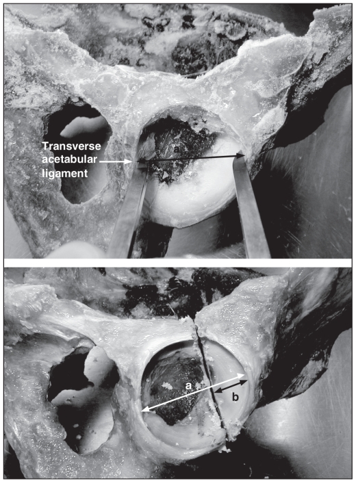
We standardized the transverse acetabular fracture. We defined the cephalad–caudad axis of the acetabulum by the greatest diameter measured from the transverse acetabular ligament to the opposite pole (Fig. 1). We created the transverse acetabular fracture at one-third the distance of the greatest acetabulum diameter from the superior pole. The osteotomy was at 90° with respect to the sagittal plane of the acetabulum (Fig. 1).
Fig. 1.
To create the transverse type fracture, first, the cephalad–caudad axis of the acetabulum is defined. This is defined by the greatest diameter (a) measured from the transverse ace-tabular ligament to the opposite pole (b). Next, the transverse ace-tabular fracture is created at one-third the distance of the greatest acetabulum diameter (i.e., 1/3 × a = b), from the superior pole.
Fixation of the fracture
Initially, we attained and temporarily fixed anatomic reduction with 2 crossed Kirschner wires (K-wires). We applied all internal fixation from the posterior aspect of the acetabulum.
Group 1: conventional plate–lag screw construct
We fixed each of the right acetabular fractures with an interfragmentary lag screw and 3.5-mm reconstruction plate. We placed the 4.5-mm interfragmentary lag screw along the posterior column in 4 of 5 specimens and along the anterior column in the fifth specimen owing to lack of satisfactory bone. We appropriately contoured an 8-hole, 3.5-mm reconstruction plate (Synthes) to the posterior column of the acetabulum, extending from the ischial tuberosity onto the iliac wing. We placed 3 screws distally into the ischial tuberosity and 3 screws proximally.
Group 2: locking plate construct
We fixed each of the left acetabular fractures with an 8-hole, 3.5-mm locking plate (Synthes) approximately contoured to the posterior column of the acetabulum, extending from the ischial tuberosity to the iliac wing, without an interfragmentary lag screw. Because the direction of the locking screws are dictated by the plate, some of the screws were directed toward the acetabulum. We measured such screws 2 mm short of the articular surface. Otherwise the locking screws attained bicortical purchase.
Biomechanical testing
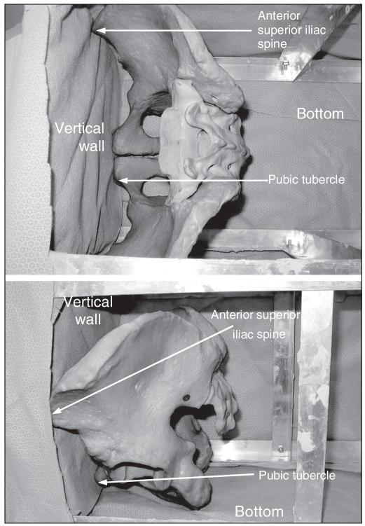
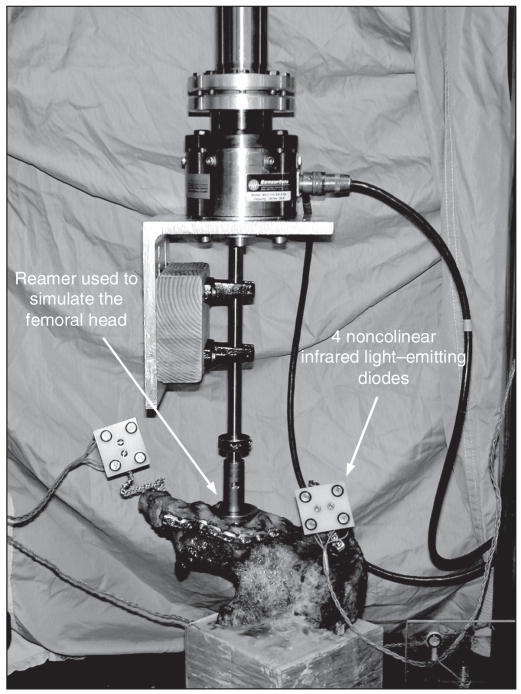
To standardize the direction in which the simulated metal femoral head was applied to the acetabulum, we first placed the pelvis in a box such that the anterior superior iliac crest was parallel to the pubic tubercles (Fig. 2). Next, we constructed a jig using a drill guide set to facilitate placement of a K-wire perpendicular to the acetabulum. We used the K-wire to indicate the direction of the force that would be applied by the simulated metal femoral head. Next, we potted each hemipelvis in a rectangular block of dental stone at the sacrum such that the K-wire would be perpendicular to the base. We used acetabular reamers connected to the load cells of the servohydraulic materials testing machine (Instron 8874; Instron Corp.) to simulate the femoral head and apply the forces at the acetabulum (Fig. 3).
Fig. 2.
(Top) Aerial and (bottom) side view of the pelvis in the anatomic position with the anterior superior iliac spine parallel to the pubic tubercles. This facilitates standardization of K-wire placement, which is used to standardize the direction of applied force at the acetabulum.
Fig. 3.
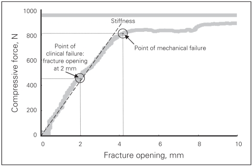
Typical curve of compressive force versus fracture gap (stress-strain curve) from specimen H1141 (right side). We defined the point of clinical failure as 2 mm of fracture gap. We defined the point of mechanical failure as a point at the end of the linear part of the curve. We defined the stiffness as a slope of linear regression among all points up to the failure point.
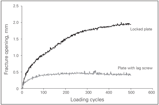
Our methodology for biomechanical testing was based on observations made during a pilot study, in which we used a sawbone model and one cadaveric specimen (conventional plate–interfragmentary lag screw construct). Initially, we had proposed to simulate normal gait based on anatomic studies that indicate that the femoral head is directed at 45° of abduction and 15° of retroversion in the standing position.20,21 However, it became apparent that at 45° of abduction and 15° of retroversion, the simulated femoral head would only load the cephalad component of the acetabular fracture, and so there was virtually no movement at the fracture site. Therefore, we decided to apply the force in such a direction as to facilitate adequate motion at the fracture site so that it could be visually appreciated, the direction being perpendicular to the acetabulum The total number of cycles applied for the “cyclic loading” test was based on the observation that the amount of fracture displacement plateaued after 500 cycles (Fig. 4). Theoretically, single stance gait applies the force equivalent to 2 body weights; however, in the pilot study, 500 N caused failure of the entire construct and only data to failure were obtained in this particular specimen. Therefore, we decided to apply a maximum of 250 N in the cyclic loading protocol.
Fig. 4.
We monitored the position of the cephalad and caudal parts of the hemipelvis by rigidly attaching 2 sets of 4 noncolinear infrared light–emitting diodes to each body.
We subjected each subsequent specimen to a compressive cyclic loading followed by a compression up to failure. The cyclic loading was a ramp compressive force in triangle waveform between 50 N and 250 N up to 500 cycles at a rate of 0.25 Hz. We monitored the increase of the fracture gap with loading cycles. In the failure test, we applied a compressive force to the specimen in load control at 150 N/s until the acetabular fixation failed. We defined “clinical failure” as an observed increase of 2 mm of fracture gap based on clinical studies that suggest that intra-articular fractures with more than 1 mm of step deformity and more than 2 mm of gap will lead to early arthritis. We defined “mechanical failure” as a point at the end of the linear part on the compressive force versus fracture gap curve (Fig. 5).
Fig. 5.
The cyclic loading test demonstrates that displacement at the fracture site plateaus at 500 cycles.
Motion measurement
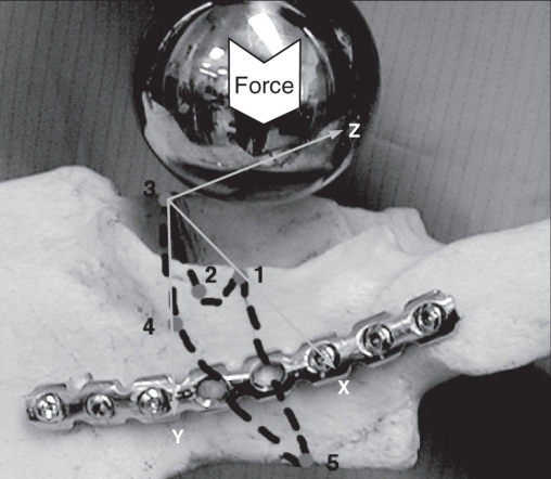
During the cyclic loading and failure test, we monitored the position of the cephalad and caudal parts of the hemipelvis by rigidly attaching 4 noncolinear infrared light-emitting diodes (LED) to each body (Fig. 3). We used an optoelectronic camera system (Optotrak 3020; Northern Digital) to measure the 3-dimensional (3-D) coordinates of the markers. This system’s resolution and accuracy is 0.1 mm. We digitized 5 points along the fracture plane using the Optotrak probe. We determined the primary (x) axis of the 3-D coordinate system by the 2 points on the rim of the acetabulum with the point on the anterior column (point #3) as the origin (Fig. 6). We determined the secondary (y) axis by the fracture plane and drew it perpendicular to the x axis (Fig. 6). We determined the “z” axis by the right-hand rule. We detected the location of greatest motion at the anterior wall of the acetabulum (point #3) (Fig. 6); thus, we chose this point as the origin of the coordinate system.
Fig. 6.
We arbitrarily assigned 5 points to the acetabulum. Motion was greatest at point 3; thus, we chose this point as the origin of the axes. We defined the x axis with respect to the edge of the anterior and posterior walls of the acetabulum. We determined the y axis by the fracture plane and drew it perpendicular to the x axis. We determined the z axis by the right hand rule.
Data analysis
We sampled the compressive force and positions of the markers at a frequency of 20 Hz in the cyclic loading test and 50 Hz in the failure test. We calculated dislocation at the origin, defined as fracture gap and rotation between the cephalad and caudal components of the anterior column from the motion of the 8 markers. In the cyclic loading test, we chose the fracture gap at 50 N of compressive force in each cycle to represent the cyclic effect on the fixation. In the failure test, we defined the stiffness of the construct as the slope of the linear region of the force versus displacement curve (Fig. 5). We also used the force versus displacement graph to define the point of failure. We recorded the amount of force that was necessary to facilitate 2 mm of fracture gap at the origin of the coordinate system (point #3) as the point of clinical failure. We also determined the corresponding amount of rotation at the origin (point #3) at the point of clinical failure. We defined mechanical failure as a point at the end of the linear part of the force versus displacement curve, representing the maximal compressive load sustained by the fixation (Fig. 5).
Statistical analysis
We analyzed differences in the compressive force, fracture gap, rotation and stiffness between the 2 fixations using Wilcoxon matched pairs test (Statistica 6.0 software; StatSoft Inc.). We calculated Spearman correlation coefficients among the fracture gap after cyclic loading, compressive force and stiffness. For all statistical tests, the significance level was assumed to be at the 95% level.
Results
The average fracture gap at 50 N compressive force after 500 loading cycles was 0.41 (standard deviation [SD] 0.49) mm for the conventional plate–interfragmentary lag screw construct compared with 0.76 (SD 0.62) mm for the locking plate fixation (Table 2). There was no difference in the fracture gap between the 2 fixations (p = 0.46). The conventional plate–interfragmentary lag screw construct had a stiffness of 456 (SD 468) N/mm, whereas the locking plate construct had a stiffness of 267 (SD 159) N/mm. There was no difference in stiffness between the 2 fixations (p = 0.34).
Table 2.
Cyclic loading test in cadaveric specimens used to compare conventional internal fracture fixation with locking plate fixation: fracture gap after cyclic loading and stiffness
| Opening after cyclical loading, mm
|
Stiffness, N/mm
|
|||
|---|---|---|---|---|
| Specimen | Conventional plate | Locking plate | Conventional plate | Locking plate |
| 1 | 0.1 | 0.3 | 1248 | 304 |
| 2 | — | 0.5 | 254 | 251 |
| 3 | 0.2 | 0.7 | 498 | 214 |
| 4 | 0.2 | 1.8 | 199 | 63 |
| 5 | 1.1 | 0.5 | 79 | 501 |
| Mean | 0.4 | 0.8 | 456 | 267 |
| SD | 0.5 | 0.6 | 468 | 159 |
SD = standard deviation.
In the failure test, on average, 848 (SD 805) N of compressive force was necessary to create a 2-mm fracture gap in the conventional plate construct and 506 (SD 277) N of compressive force was necessary to create a 2-mm gap in the locked plate construct (Table 3). There was no significant difference between the 2 fixations (p = 0.34). An average 1012 (SD 557) N of force was necessary to cause mechanical failure of the conventional construct and 920 (SD 444) N of force was necessary to reach the point of mechanical failure in the locking plate construct (p = 0.50) (Table 3). At the point of clinical failure, the amount of rotation at the fracture site was 1.8° (SD 0.6°) in the conventional group and 1.9° (SD 0.7°) in the locking plate group (p = 0.34) (Table 4). At the point of mechanical failure, there was 3.4° (SD 1.8°) of rotation at the fracture site in the conventional group and 5.0° (SD 1.7°) of rotation in the locking plate group (p = 0.22) (Table 4).
Table 3.
Failure test in cadaveric specimens used to compare conventional internal fracture fixation with locking plate fixation: compressive force
| Compressive force, N
|
||||
|---|---|---|---|---|
| At 2 mm opening
|
At failure point
|
|||
| Specimen | Conventional plate | Locking plate | Conventional plate | Locking plate |
| 1 | 2145 | 713 | 1908 | 1620 |
| 2 | 471 | 374 | 609 | 1032 |
| 3 | 1074 | 514 | 1174 | 713 |
| 4 | 453 | 117 | 816 | 443 |
| 5 | 98 | 814 | 554 | 791 |
| Mean | 848 | 506 | 1012 | 920 |
| SD | 805 | 277 | 557 | 444 |
SD = standard deviation.
Table 4.
Failure test in cadaveric specimens used to compare conventional internal fracture fixation with locking plate fixation: rotation
| Rotation between fractured parts; degrees
|
||||
|---|---|---|---|---|
| At 2 mm opening
|
At failure point
|
|||
| Specimen | Conventional plate | Locking plate | Conventional plate | Locking plate |
| 1 | 2.9 | 1.4 | 1.5 | 5.5 |
| 2 | 1.8 | 2.0 | 4.8 | 6.2 |
| 3 | 1.3 | 1.5 | 1.9 | 3.4 |
| 4 | 1.3 | 3.1 | 3.1 | 6.8 |
| 5 | 1.6 | 1.7 | 5.6 | 3.1 |
| Mean | 1.8 | 1.9 | 3.4 | 5.0 |
| SD | 0.6 | 0.7 | 1.8 | 1.7 |
SD = standard deviation.
As an internal validation of the results, we evaluated the relation between the compressive force measured in the failure tests and the amount of fracture displacement measured in the cyclic loading tests. There was a significant correlation between the rigidity of the constructs (clinical failure r2 = 0.69, p = 0.005; biomechanical failure r2 = 0.81, p = 0.002) and the amount of displacement at the fracture site measured in the cyclic loading tests. Furthermore, the fracture gap after cyclic loading correlated significantly with the stiffness of the construct (r2 = 0.58, p = 0.016) .
Discussion
Articular incongruity of acetabulum fractures is associated with the long-term risk of degenerative arthritis,15,17,22,23 and the biggest challenge in treating acetabulum fractures is to attain adequate fracture reduction. Maintaining the reduction as the internal fixation is being applied can be difficult. Locking plates have some theoretical advantages for acetabular fracture fixation. Unlike with conventional plates, perfect contouring of the locking plate is not necessary, and the plate does not force the bone to fit the plate. Therefore the locking plate is less likely to act as a deforming construct disrupting fracture reduction. Furthermore, if strong enough, the locking plate may be used in place of the conventional plate–interfragmentary lag screw construct. Thus depending on the fracture pattern, locking plates may potentially eliminate the need for an interfragmentary lag screw, which can be technically challenging to insert in acetabular fracture fixation. However, biomechanical studies indicate that the interfragmentary lag screw confers additional strength to the conventional plate fixation.16,18 Therefore, we decided that the optimum conventional fixation would consist of an interfragmentary lag screw plus a posterior plate, though we accept that in vivo this is technically not always possible. In view of the limited number of specimens and biomechanical testing to failure, we tested no other conventional fracture fixation configurations. In contrast, the experimental fixation consisted of a single posterior locking plate.
A transverse fracture configuration is one of the complex fracture patterns that may be fixed with either an interfragmentary lag screw–plate construct or a posterior plate alone. In comparison, T-type or 2-column fractures theoretically require a lag screw, particularly if the operation is carried out through a single exposure. The transverse fracture configuration is easily reproducible and testing data are available from other studies16,18 for comparison.
Our results demonstrate a nonsignificant trend favouring the conventional plate–interfragmentary lag screw construct. The stiffness of the conventional construct (456, SD 468 N/mm) was greater than that of the locking plate construct (267, SD 159 N/mm) (p = 0.34). After 500 cycles of loading the models, there was 0.41 (SD 0.49) mm of gap at the fracture site in the conventional group and 0.76 (SD 0.62) mm in the locking plate group (p = 0.46). With regards to the failure tests, there was also a nonsignificant trend favouring the conventional construct. An average of 848 (SD 805) N of compressive force was necessary to create a 2-mm fracture gap in the conventional plate construct and 506 (SD 277) N of compressive force was necessary to create a 2-mm gap in the locking plate construct (p = 0.34). The standard deviation in all the results was quite large, which may be attributed to the variation in the cadaveric specimens.
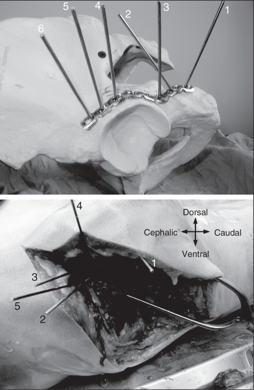
Although the conventional construct appears to be stronger than the locking screw construct, the latter construct still may be safe in vivo. Our results suggest that after 500 cycles of cyclic loading, there is still less than 1 mm of gap at the fracture site. However, there are also important technical considerations particular to locking plates. An important issue is the trajectory of the locked screw, which is dictated by the screw holes. In our study, once we approximately contoured the plate to fit the posterior column, there was a consistent finding that 2 of the screws would be directed into the acetabulum. This finding was not influenced by more accurate contouring of the plate. We further evaluated potential joint penetration on a sawbone model (Fig. 7). The pins numbered 4, 5 and 6 indicate that the 3 proximal screws could potentially penetrate the articular surface. Therefore, even if unicortical screws are used, the screws should be used with caution.
Fig. 7.
(Top) Trajectory of locking screws are demonstrated using the guidewires and a sawbone model. It is apparent that screw numbers 4, 5 and 6 will be directed toward the articular surface. (Bottom) Trajectory of locking screws are demonstrated using the guidewires and an embalmed cadaveric specimen. The screw corresponding to the one numbered 6 in panel A cannot be placed because of overlying soft tissue.
Another concern is the influence of the surrounding soft tissues on screw placement as the locked screws have to be drilled and inserted at a particular angle to facilitate locking of the screw to the plate. To determine potential limitations of overlying soft tissues, we exposed and plated the posterior column of a cadaveric specimen that had been embalmed using a technique to preserve tissue flexibility using a locking plate. This demonstrated that the most proximal screw could not be inserted because of overlying soft tissues (Fig. 7).
Our study has several strengths. We used paired specimens to test the 2 modes of fixation, effectively eliminating the intrahost factor variables. We believe that a cadaveric model replicates in vivo conditions more closely than saw bones or other synthetic models. We created the acetabular fractures in a standardized and reproducible fashion. We performed cyclic loading tests to simulate the repeated force that is applied to the construct in gait. We believe that this testing may be more important than failure tests because it is the repeated stress of daily activities that may cause fixation failure. We were also able to measure the displacement at the fracture site in a 3-D plane.
All biomechanical studies have certain limitations. Some would correctly state that artificially created fractures do not closely simulate in vivo conditions. Furthermore, in vivo, the pelvis is enveloped in strong musculature which, though it can cause deforming forces, can provide weak fracture support and a vital fracture healing environment. It is very difficult, however, to simulate all of the mechanical forces applied by the surrounding musculature and ligaments during activities of daily living, and in-vivo cyclic loading tests are done without any consideration of any evolving fracture callus that may improve the strength of the construct. Most acetabular fractures that require surgery occur in younger patients; however, the cadaveric specimens for this study were from an older population. Four of 5 specimens had a lag screw placed along the posterior column, but 1 specimen had to have the lag screw placed along the anterior column. Interestingly, the specimen with the lag screw along the anterior column constituted the weakest construct in the conventional plate group. The cadaveric specimens underwent reaming of each acetabulum, which may have compromised some of the anterior and posterior column bone stock. However, one may argue that the limitations of cadaveric specimens from older donors, acetabular reaming and an anterior interfragmentary lag screw simulates the worst-case scenario, which could potentially benefit from a locking plate construct, as demonstrated in other areas of the body.
It is always difficult to acquire enough cadaveric specimens to conduct parametric statistical analysis of the results. Nonparametric statistical tests have less power for detecting differences. Based on our results, 48 paired specimens would be necessary to detect a difference between the 2 fixations. Testing of other fracture fixation configurations would clearly require considerable numbers.
Acetabular fracture fixation remains challenging, and often technical considerations mean that optimal conventional fixation such as with an interfragmentary lag screw may not be possible. With due consideration to the soft-tissue constraints and the possibility of joint penetration, locking plates may still have a role in the management of acetabular fractures. However, the real practical implication of our study is 2-fold. First, locking plates may be used for revision hip arthroplasty in patients with pelvic discontinuity. This scenario is usually associated with osteolysis and poor bone quality that would be best served by locking plate technology. Second, with regards to acetabular fractures, this technology may have a role in osteoporotic bone and in double plating of posterior column/wall fractures and may potentially obviate the use of interfragmentary screws.
Footnotes
Competing interests: None declared for Drs. Mehin, Zhu and Broekhuyse. Dr. Jones has received travel assistance from Stryker.
Contributors: Drs. Mehin, Jones and Broekhuyse designed the study. Drs. Jones and Zhu acquired the data, which Drs. Hehin, Zhu and Broekhuyse analyzed. Drs. Mehin, Jones and Zhu wrote the article. All authors reviewed the article and approval its publication.
References
- 1.Frigg R. Development of the locking compression plate. Injury. 2003;34(Suppl 2):B6–10. doi: 10.1016/j.injury.2003.09.020. [DOI] [PubMed] [Google Scholar]
- 2.Frigg R. Locking Compression Plate (LCP). An osteosynthesis plate based on the Dynamic Compression Plate and the Point Contact Fixator (PC-Fix) Injury. 2001;32(Suppl 2):63–6. doi: 10.1016/s0020-1383(01)00127-9. [DOI] [PubMed] [Google Scholar]
- 3.Perren SM. Evolution of the internal fixation of long bone fractures. The scientific basis of biological internal fixation: choosing a new balance between stability and biology. J Bone Joint Surg Br. 2002;84:1093–110. doi: 10.1302/0301-620x.84b8.13752. [DOI] [PubMed] [Google Scholar]
- 4.Egol KA, Kubiak EN, Fulkerson E, et al. Biomechanics of locked plates and screws. J Orthop Trauma. 2004;18:488–93. doi: 10.1097/00005131-200409000-00003. [DOI] [PubMed] [Google Scholar]
- 5.Farouk O, Krettek C, Miclau T, et al. Minimally invasive plate osteosynthesis and vascularity: preliminary results of a cadaver injection study. Injury. 1997;28(Suppl 1):A7–12. doi: 10.1016/s0020-1383(97)90110-8. [DOI] [PubMed] [Google Scholar]
- 6.Farouk O, Krettek C, Miclau T, et al. Minimally invasive plate osteosynthesis: Does percutaneous plating disrupt femoral blood supply less than the traditional technique. J Orthop Trauma. 1999;13:401–6. doi: 10.1097/00005131-199908000-00002. [DOI] [PubMed] [Google Scholar]
- 7.Baumgaertel F, Buhl M, Rahn BA. Fracture healing in biological plate osteosynthesis. Injury. 1998;29(Suppl 3):C3–6. doi: 10.1016/s0020-1383(98)95002-1. [DOI] [PubMed] [Google Scholar]
- 8.Hofer HP, Wildburger R, Szyszkowitz R. Observations concerning different patterns of bone healing using the Point Contact Fixator (PC-Fix) as a new technique for fracture fixation. Injury. 2001;32(Suppl 2):B15–25. doi: 10.1016/s0020-1383(01)00122-x. [DOI] [PubMed] [Google Scholar]
- 9.Cole PA, Zlowodzki M, Kregor PJ. Less Invasive Stabilization System (LISS) for fractures of the proximal tibia: indications, surgical technique and preliminary results of the UMC Clinical Trial. Injury. 2003;34(Suppl 1):A16–29. doi: 10.1016/s0020-1383(03)00254-7. [DOI] [PubMed] [Google Scholar]
- 10.Haidukewych GJ. Innovations in locking plate technology. J Am Acad Orthop Surg. 2004;12:205–12. doi: 10.5435/00124635-200407000-00001. [DOI] [PubMed] [Google Scholar]
- 11.Drobetz H, Kutscha-Lissberg E. Osteosynthesis of distal radial fractures with a volar locking screw plate system. Int Orthop. 2003;27:1–6. doi: 10.1007/s00264-002-0393-x. [DOI] [PMC free article] [PubMed] [Google Scholar]
- 12.Leung F, Zhu L, Ho H, et al. Palmar plate fixation of AO type C2 fracture of distal radius using a locking compression plate — a biomechanical study in a cadaveric model. J Hand Surg [Br] 2003;28:263–6. doi: 10.1016/s0266-7681(03)00011-1. [DOI] [PubMed] [Google Scholar]
- 13.Ruch DS, Weiland AJ, Wolfe SW, et al. Current concepts in the treatment of distal radial fractures. Instr Course Lect. 2004;53:389–401. [PubMed] [Google Scholar]
- 14.Fankhauser F, Boldin C, Schippinger G, et al. A new locking plate for unstable fractures of the proximal humerus. Clin Orthop Relat Res. 2005;(430):176–81. doi: 10.1097/01.blo.0000137554.91189.a9. [DOI] [PubMed] [Google Scholar]
- 15.Matta JM. Fractures of the acetabulum: accuracy of reduction and clinical results in patients managed operatively within three weeks after the injury. J Bone Joint Surg Am. 1996;78:1632–45. [PubMed] [Google Scholar]
- 16.Chang JK, Gill SS, Zura RD, et al. Comparative strength of three methods of fixation of transverse acetabular fractures. Clin Orthop Relat Res. 2001;(392):433–41. doi: 10.1097/00003086-200111000-00057. [DOI] [PubMed] [Google Scholar]
- 17.Mears DC, Velyvis JH, Chang CP. Displaced acetabular fractures managed operatively: indicators of outcome. Clin Orthop Relat Res. 2003;(407):173–86. doi: 10.1097/00003086-200302000-00026. [DOI] [PubMed] [Google Scholar]
- 18.Shazar N, Brumback RJ, Novak VP, et al. Biomechanical evaluation of transverse acetabular fracture fixation. Clin Orthop Relat Res. 1998;(352):215–22. [PubMed] [Google Scholar]
- 19.Simonian PT, Routt ML, Jr, Harrington RM, et al. The acetabular T-type fracture. A biomechanical evaluation of internal fixation. Clin Orthop Relat Res. 1995;(314):234–40. [PubMed] [Google Scholar]
- 20.Bergmann G, Graichen F, Rohlmann A. Hip joint loading during walking and running, measured in two patients. J Biomech. 1993;26:969–90. doi: 10.1016/0021-9290(93)90058-m. [DOI] [PubMed] [Google Scholar]
- 21.Witte H, Eckstein F, Recknagel S. A calculation of the forces acting on the human acetabulum during walking Based on in vivo force measurements, kinematic analysis and morphometry. Acta Anat (Basel) 1997;160:269–80. doi: 10.1159/000148021. [DOI] [PubMed] [Google Scholar]
- 22.Mayo KA. Open reduction and internal fixation of fractures of the acetabulum. Results in 163 fractures. Clin Orthop Relat Res. 1994;(305):31–7. [PubMed] [Google Scholar]
- 23.Murphy D, Kaliszer M, Rice J, et al. Outcome after acetabular fracture. Prognostic factors and their inter-relationships. Injury. 2003;34:512–7. doi: 10.1016/s0020-1383(02)00349-2. [DOI] [PubMed] [Google Scholar]


