Abstract
Purpose
To report the use of a semiburied curvilinear distraction device, with a 3-D CT treatment planning system, for correction of mandibular deformities.
Methods
This is a retrospective evaluation of 13 consecutive patients, with syndromic and non-syndromic micrognathia, who underwent correction by curvilinear distraction osteogenesis. A 3-D CT scan was obtained for each patient and imported into a 3-D treatment planning system (Slicer/Osteoplan™). Surgical guides were constructed to localize the osteotomy and to drill holes for securing the distractor’s proximal and distal footplates to the mandible. Postoperatively, patients were followed by clinical examination and plain radiographs to ensure the desired vector of movement. At end distraction, when possible, a 3-D CT scan was obtained to document the final mandibular position.
Results
Eight females and 5 males with a mean age of 11.9 years (range=15months–39 years) underwent bilateral mandibular curvilinear distraction. Eight of the 13 patients were 16 years or younger and 5 were less than 6 years of age. The diagnoses included Treacher Collins (n=3) and Nager (n=3) syndromes, craniofacial microsomia (n=2), post-traumatic ankylosis (n=1), and micrognathia (syndromic, n=3; non-syndromic, n=1). Correct distractor placement, vector of movement and final mandibular position were achieved in 10/13 patients. In the other 3 patients, desired jaw position was achieved by “molding” the regenerate.
Conclusion
The use of a semiburied curvilinear distraction device, with 3-dimensional treatment planning, is a potentially powerful tool to correct complex mandibular deformities.
INTRODUCTION
Trauner1 was the first to apply Euclidean principles to the planning of orthognathic surgical corrections. More recently, Seldin et al2 observed that combinations of translational and rotational movements could be resolved into a simple rotation about a unique axis determined by algebraic or geometric means. The geometric axes for a proposed surgical correction define the simplest path of the skeletal movement to achieve the desired result. Thus, a simple curvilinear device with a specific radius of curvature can be constructed to correct any mandibular deformity. Understanding this principle, allows the development of novel devices that are not limited to linear movements and that do not necessarily depend on screw-type propulsion mechanisms.
We have designed, produced and demonstrated the use of a semi-buried, fixed-trajectory curvilinear distraction device, propelled by a rack and worm gear, in a mini-pig model.2 Curvilinear devices with a flexible screw type propulsion mechanism have subsequently been described by others3. Because a buried device does not permit mid-course correction, accurate treatment planning is critical to ensure the desired final skeletal position. We have therefore developed a computed tomography (CT) based 3-dimensional (3-D) treatment planning system4, 5, 6, 7 to be used with a semiburied curvilinear distraction device to obtain advancement and counterclockwise rotation of the mandible.
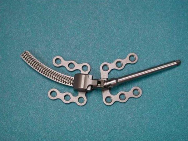
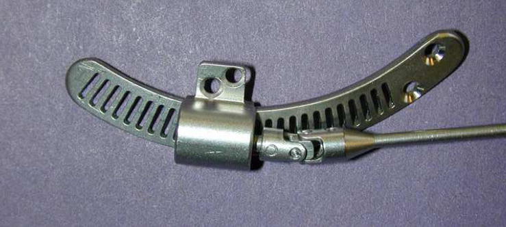
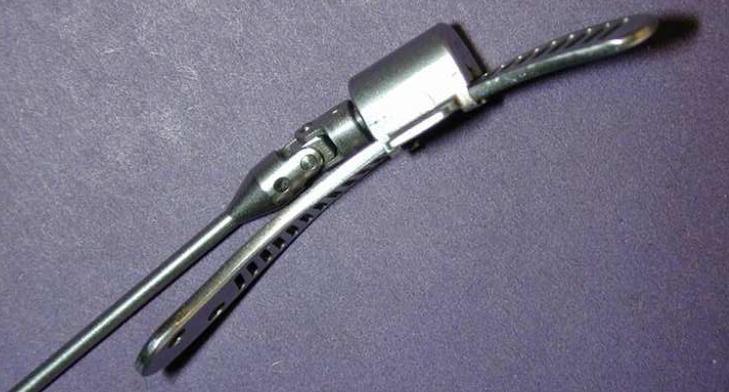
The purpose of this study is to report the clinical application of a semiburied, fixed-trajectory, curvilinear distraction device (Figure 1), used in conjunction with a CT-based 3D treatment planning system, to correct mandibular deformities.
Figure 1.
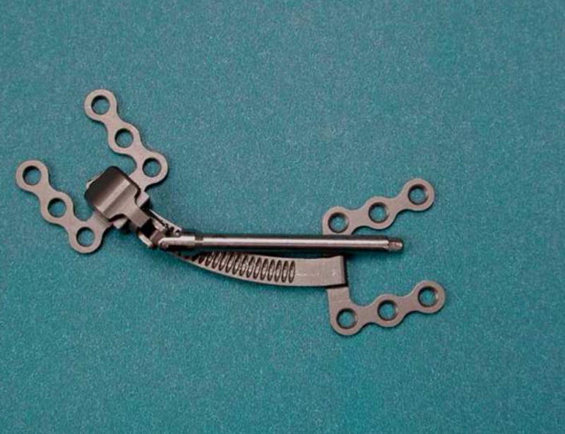
(A) Semiburied, curvilinear distraction device (Synthes CMF, West Chester, PA) for left ramus: Radius of curvature 5cm, elongation parameter 25mm (Note the worm gear housing and the curved track along which distractor and distal mandible move). (B) Device fully activated.
MATERIALS AND METHODS
Patients, Clinical and Radiographic Follow-up
This is a retrospective case series of 13 consecutive patients who underwent bilateral mandibular osteotomies and placement of custom-made curvilinear distraction devices (Synthes CMF, West Chester, PA) to correct severe mandibular retrognathism with and without open bite. All patients underwent a diagnostic work-up including history, physical examination, photographs, anterior-posterior and lateral cephalograms, panoramic radiographs, dental models and computed tomographic scans (axial and coronal 1mm cuts with 3-dimensional reconstruction). Distractor placement was verified by anterior-posterior (AP) and lateral cephalometric and panoramic radiographs within 48 hours of the operation. Patients were evaluated by clinical examination every other day initially and then weekly once it was determined that they were distracting properly and that the planned movement was being achieved.
Serial radiographs to document vectors of movement were obtained weekly and at the end of distraction. When possible, a repeat 3-D CT scan was obtained at the end of the fixation period and the treatment planning system was used to superimpose the preoperative, predicted and actual outcome.
3-D Treatment Planning and Navigation
A 3-D virtual model of the skull and mandible was reconstructed from standard 1 mm axial and coronal CT cuts. (Figure 2) The 3-D data were imported into a treatment planning system (3-D Slicer/Osteoplan™) created and tested in collaboration with the Harvard Surgical Planning Laboratory (SPL).4, 5, 6, 7. This is a free open source software packet for 3-D visualization and image analysis that was developed with funding from NIH (www.slicer.org).
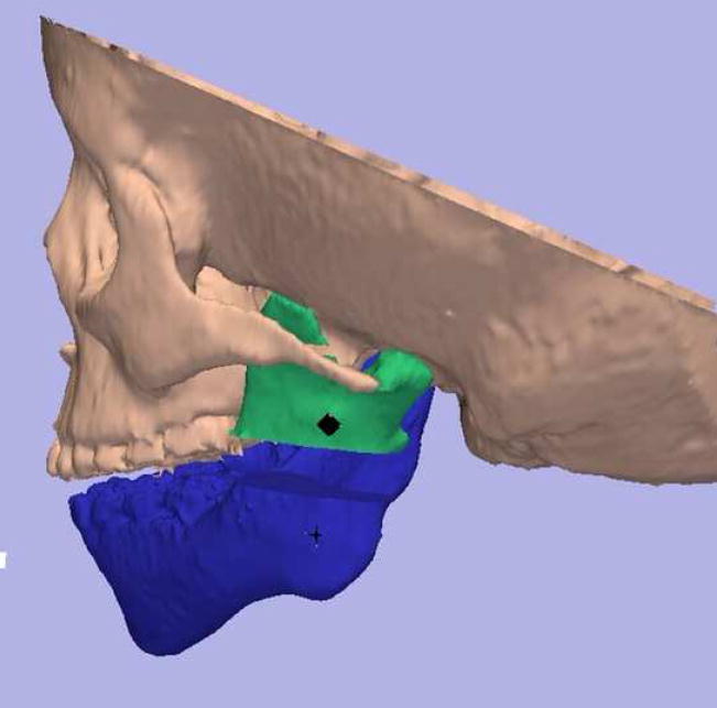
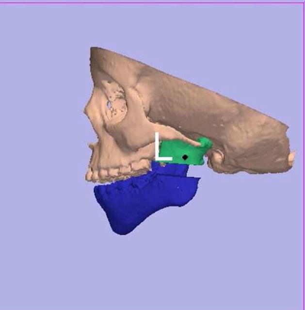
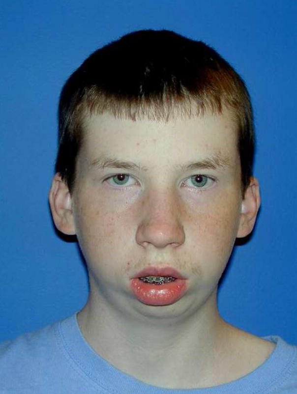
Figure 2.
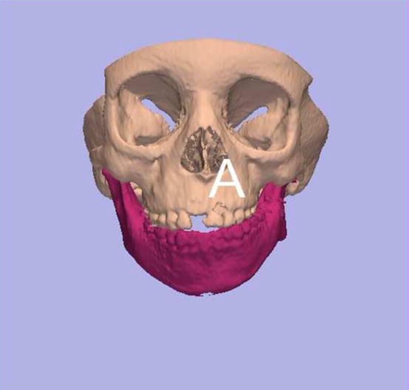
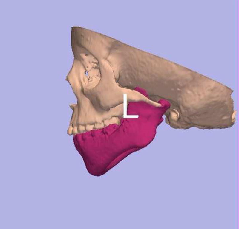
(A) Frontal and (B) left lateral view of 3-D CT model of patient with left hemifacial microsomia. Note long coronoid process relative to condyle.
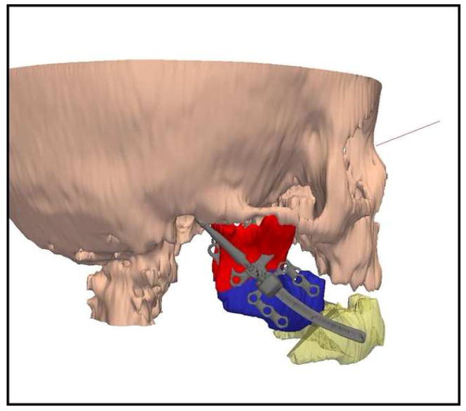
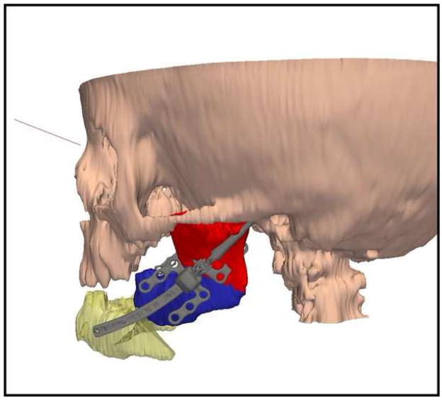
Reproducible landmarks and regions of the osteotomies on each side of the mandible were identified on the 3D scans using Osteoplan™.4, 5, 7, 8, 9 With the cutting tool, osteotomies were performed and the mandible was moved to the proposed postoperative position. The system warns the operator of any potential bony collisions (interferences) along the path of movement. (Figure 3) These bony interferences can then be modified. For example, in patients with skeletal type II hemifacial microsomia, the elongated coronoid process may collide with the skull base before the shorter condyle reaches its destination, thereby preventing the desired mandibular ramus elongation. A coronoidectomy is performed to eliminate this problem (Figure 3). The axis of the proposed movement on each side, the radius of curvature of the distraction devices, their lengths and locations are all calculated by the software program and illustrated on the images (Figures 4, 5).
Figure 3.
(A) Software program warns of interferences. Left coronoid collides with skull base prior to completion of desired ramus lengthening. Coronoidectomy allows room for movement of the condyle to skull base. (B) Coronoidectomy performed, allowing distraction of ramus without collision.
Figure 4.
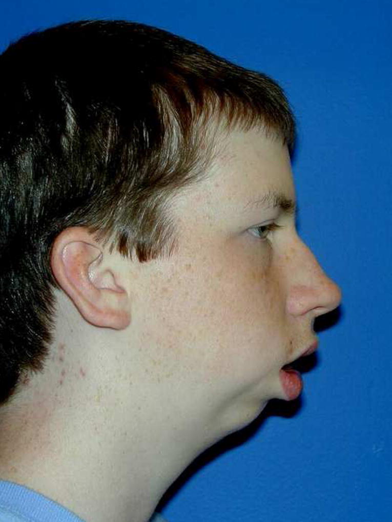
(A) Frontal and (B) lateral views of patient with severe micrognathia and obstructive sleep apnea (Barr-Shaver-Carr Syndrome). Goals were to lengthen posterior face height and advance and rotate the mandible in a counterclockwise direction. At the time of device removal a LeFort I osteotomy was planned.
Figure 5.
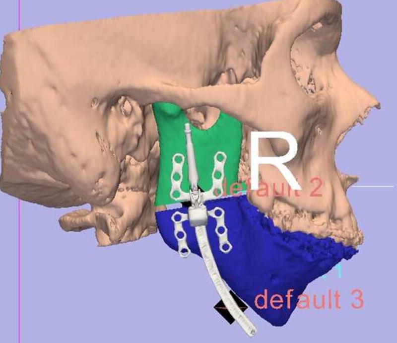
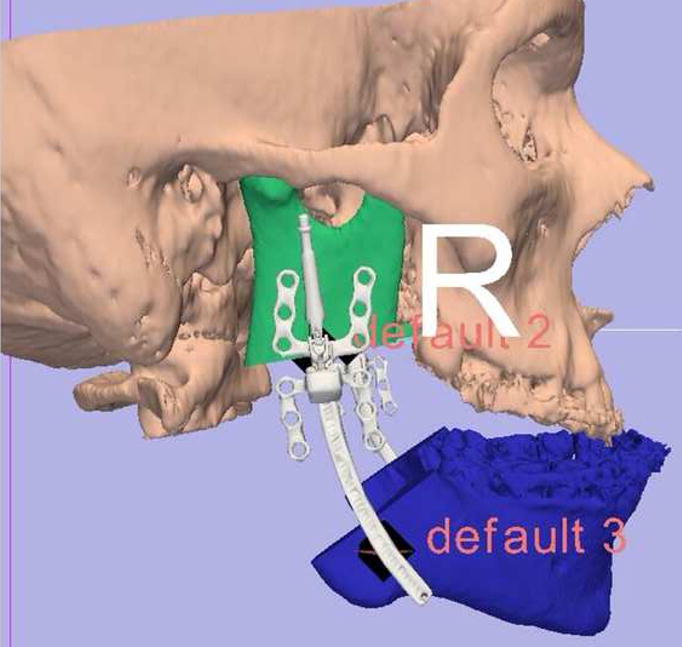
Using Osteoplan™, osteotomy and desired movements were accomplished (for patient in Figure 4) on the virtual model. Distractor parameters were calculated and the device manufactured (Synthes CMF, West Chester, PA). (Left side actual measurements: radius of curvature (ROC) 6.0 cm, elongation 30mm; distractor chosen: ROC 7.0 cm, length 40mm. Right side actual measurements: ROC 7.0 cm, elongation 32mm; distractor chosen: ROC 7.0 cm, elongation 40mm). Anatomically appropriate footplates were chosen to be fixed to proximal and distal segments of the mandible. Others were removed.
Correct placement and orientation of the osteotomies and distraction devices are critical to the success of treatment. In the first 6 patients navigation devices, indexed to the teeth, were constructed to properly localize the ostetotomies during the operation. The face-bow articulated dental models were situated to correspond to the position of the teeth on the 3-D image. A metal rod was bent and attached to an acrylic occlusal wafer that related the osteotomy location and orientation to the occlusal plane. The distraction devices were placed free hand by observation of their location relative to the osteotomies.
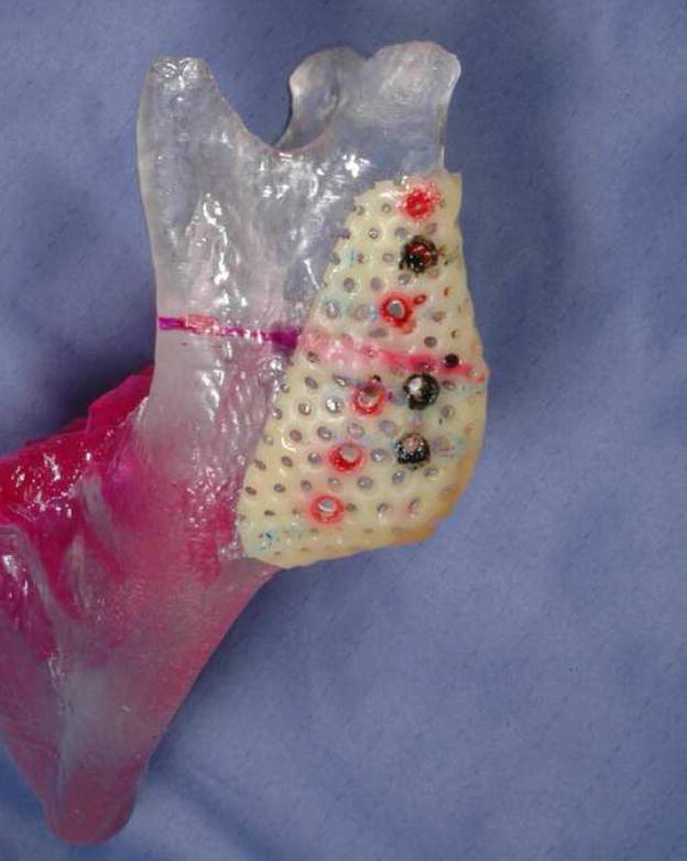
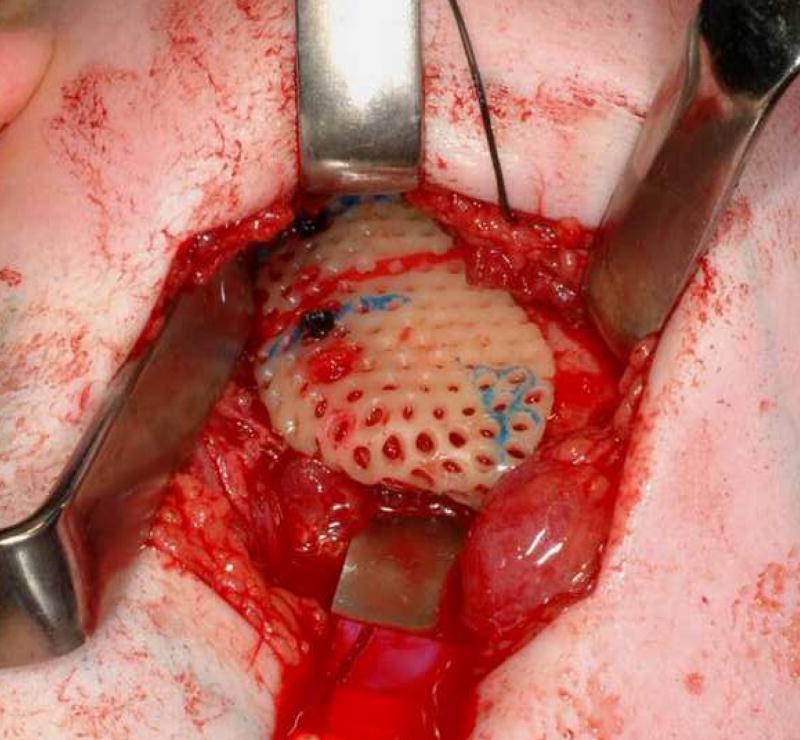
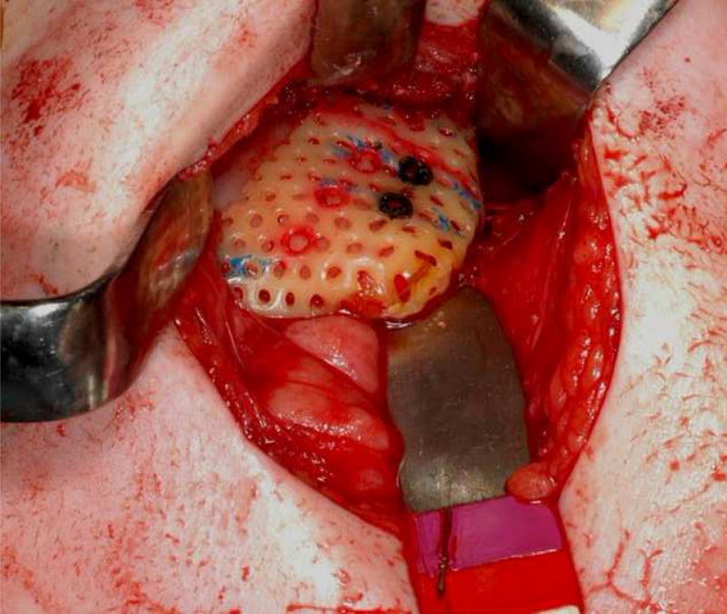
This method proved to be imprecise and in subsequent patients, a 3-D acrylic model of the mandible was created from the CT data and an Aquaplast (Aquaplast Corporation, Wycoff, NJ) stent was constructed to fit onto the ramus. The osteotomy was drawn on the stent and holes were drilled through the stent into the mandibular model to help localize the device as prescribed by the software. The footplates of the distraction device were then bent to lie flush with the bone and allow the devices to be as parallel as possible to one another and to the mid-sagittal plane. Osteotomy and distraction were then carried out on the model to ensure the correct movement. The stent was sterilized and used intra-operatively to accurately localize the osteotomies and drill holes for distractor footplate placement. (Figure 6)
Figure 6.
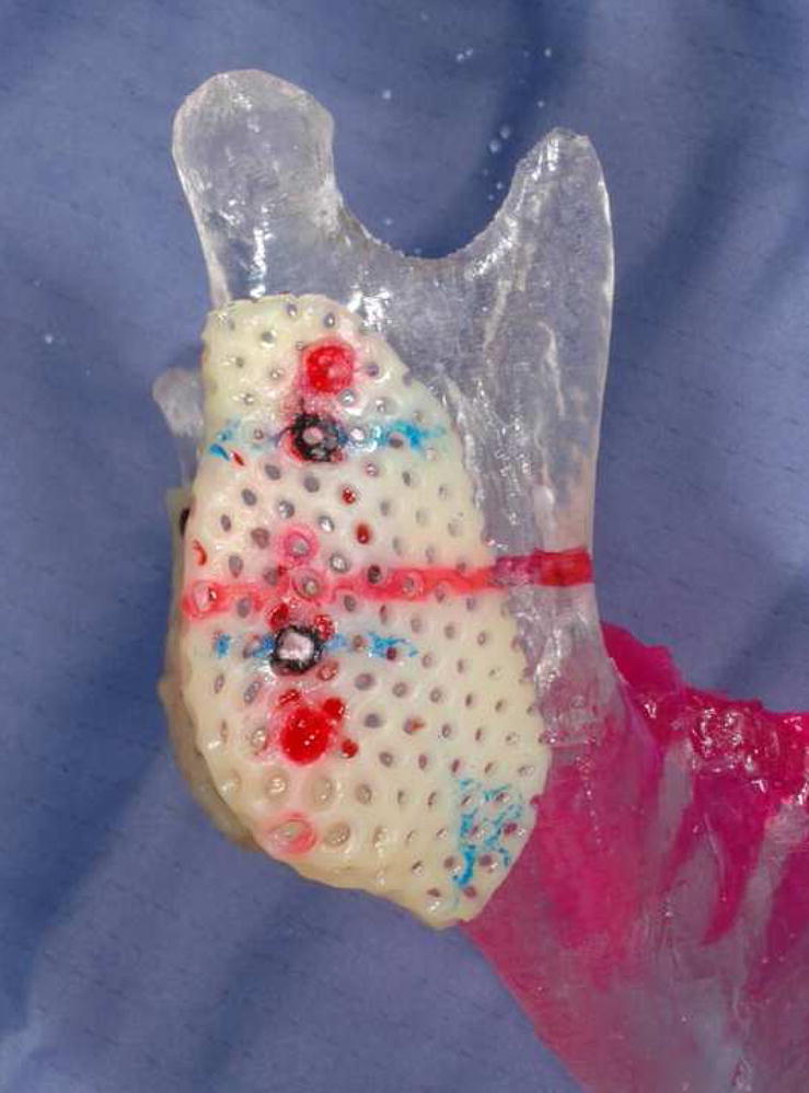
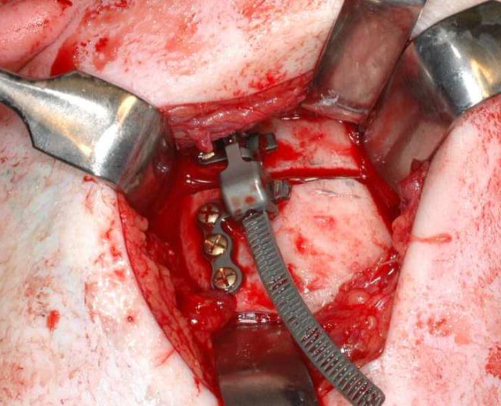
(A & B) Aquaplast was molded to both sides of ramus on 3D model. Osteotomies were drawn and distractor oriented on model. Holes were drilled to localize footplates thereby orienting osteotomy and device properly. (C & D) Intraoperative photographs of stents fitted onto the right and left rami. Osteotomy location and orientation marked on bone and holes drilled to localize and secure footplates. (E & F) Right and left distractors in place across osteotomies.
Surgical Procedure
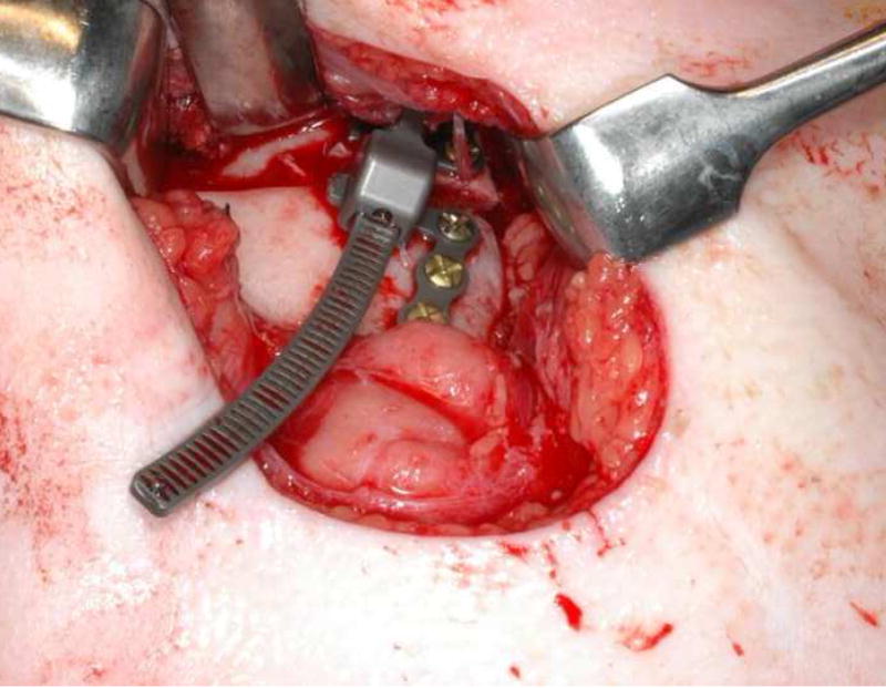
Under nasoendotracheal anesthesia, the mandible is exposed via a submandibular or intraoral incision and dissection depending on the size of the patient and anatomy of the ramus. The stent is placed on the mandibular ramus duplicating its position on the model. It serves as an intraoperative template for the osteotomy and drilling the holes that accurately localize the distraction devices. (Figures 6, 7)
Figure 7.
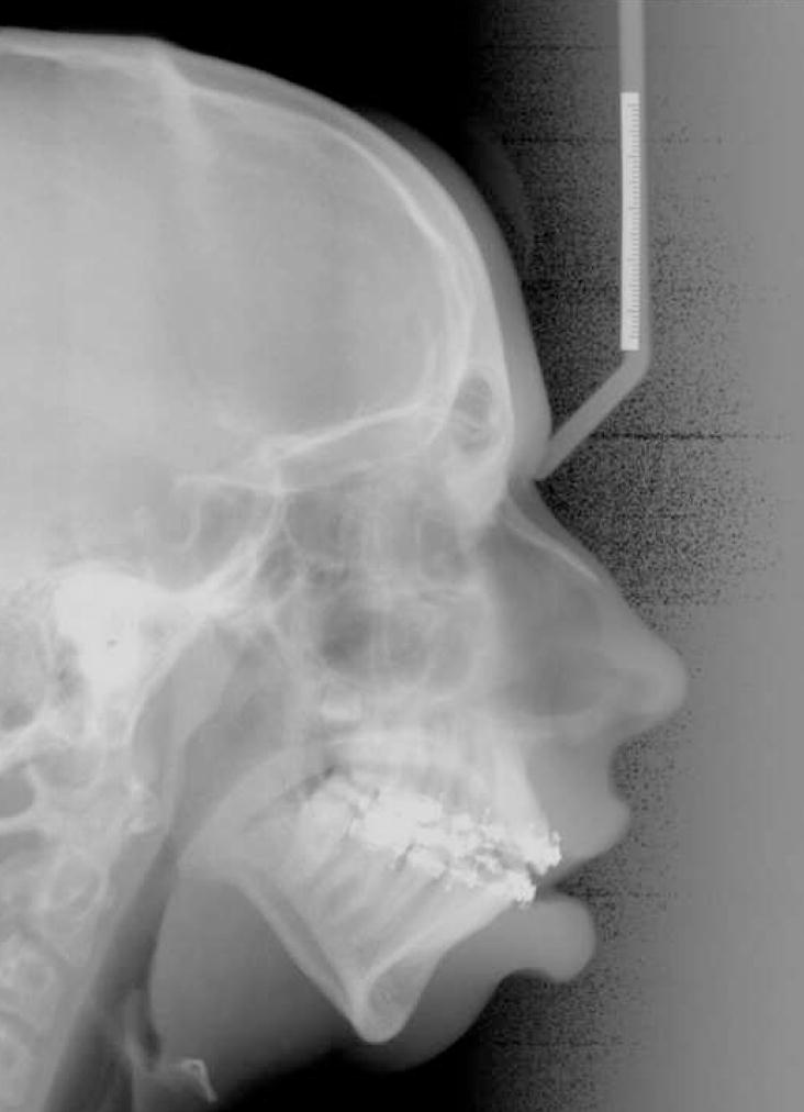
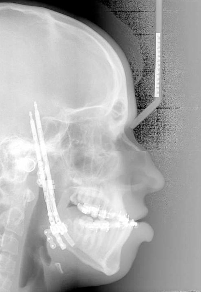
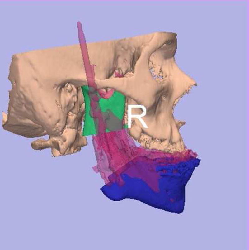
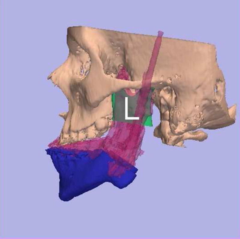
(A) Preoperative and (B) end distraction lateral cephalograms. Posterior airway space increased from 5.03 to 18.96mm and distance from hyoid to mandible decreased from 19.3 to12.9mm (normal values 11 and <15mm respectively). Overlay of predicted (blue) and end-fixation (pink) position of (C) right and (D) left sides of mandible demonstrating the desired movement was achieved.
With the stent in place, holes for the device footplates are drilled. The stent is removed and the bone cut is drawn with a pencil and then executed with a reciprocating saw. The distraction device is fit in place and fixed with four 2 mm diameter screws (2 screws on the proximal and two screws on the distal fragment). The osteotomy is completed with an osteotome. The device is activated until a wedge-shaped gap is demonstrated and then the distractor is turned back to the neutral position. The same procedure is repeated on the opposite side. The wounds are irrigated and closed in layers.
Distraction is begun after a latency period of 48–96 hours and carried out at a rate of 1 full turn per day (approximately 1mm per day). The fixation period is at least 2 times the number of millimeters of distraction in days or until the defect is filled in with bone by CT scan (Figures 7, 8, 9, 10, 11).
Figure 8.
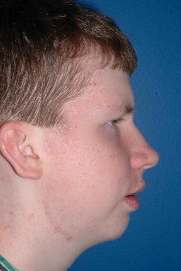
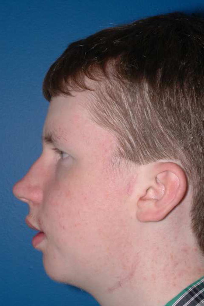
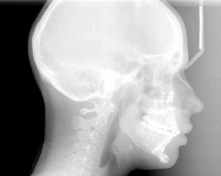
(A) Frontal, (B & C) lateral photographs and (D) lateral cephalogram of patient 1 year after removal of distraction devices and LeFort I osteotomy to correct posterior open bite created by curvilinear distraction of mandible.
Figure 9.
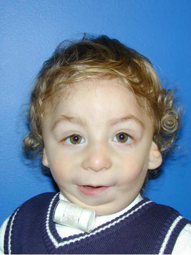
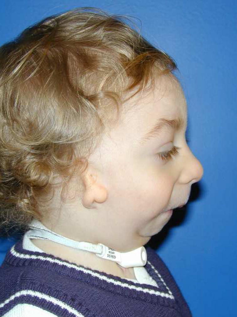
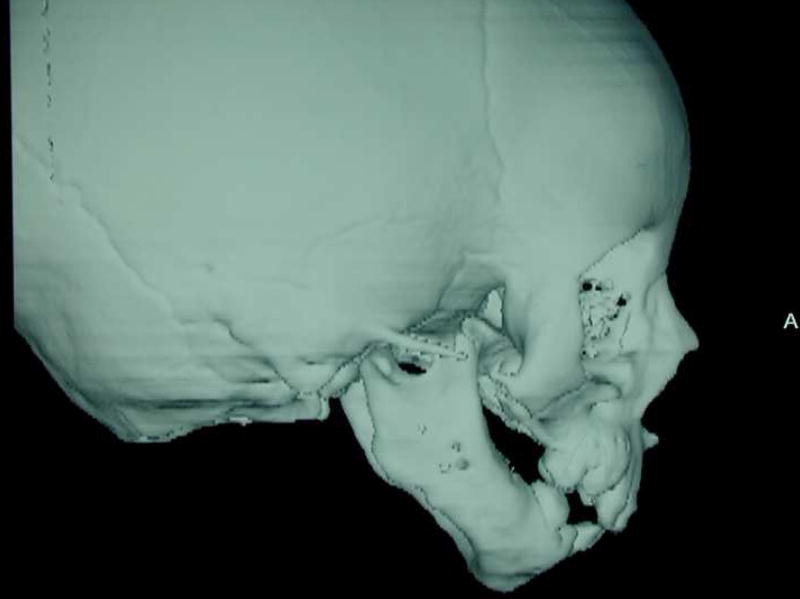
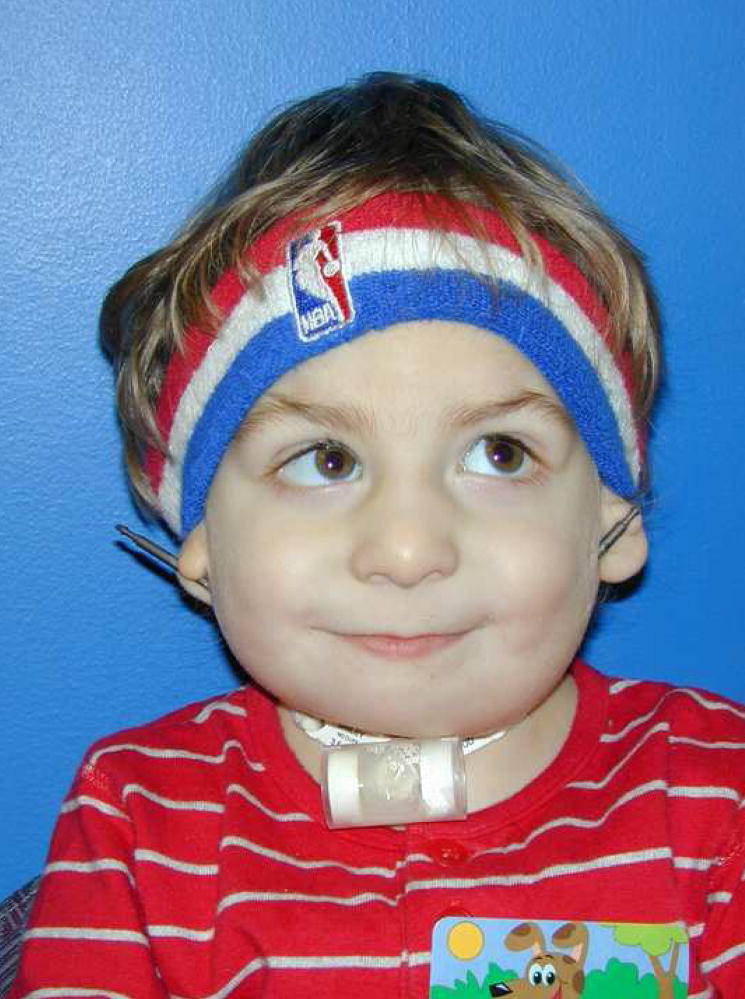
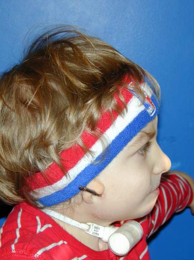
(A) Frontal and (B) lateral views of a 2.5-year-old boy with bilateral craniofacial microsomia who is tracheostomy dependent secondary to severe micrognathia. (C) Frontal and (D) lateral 3-D CT scans demonstrating the skeletal deformity.
Figure 10.
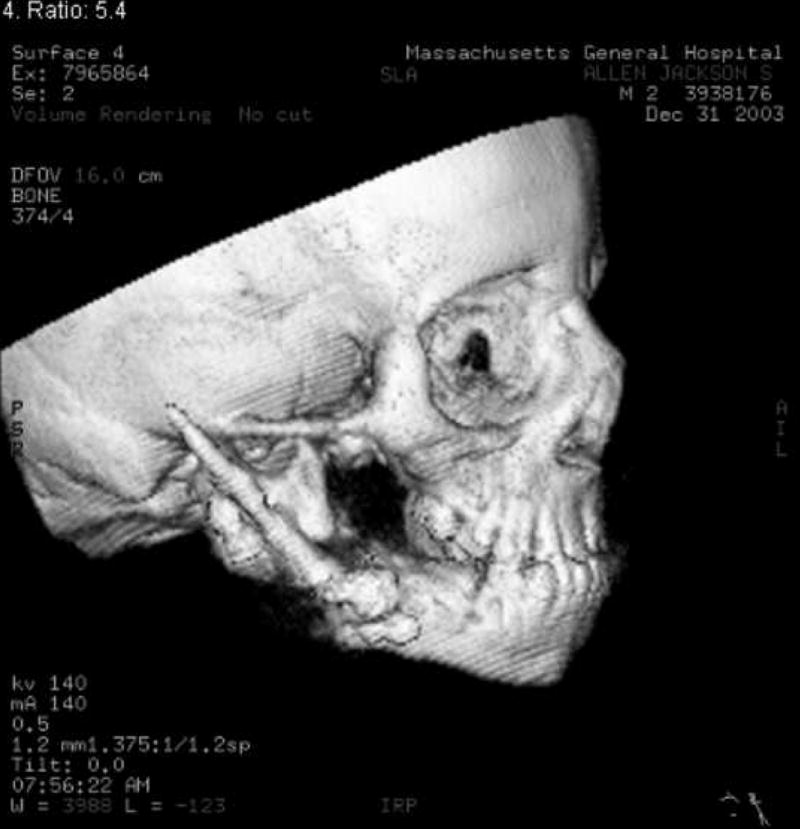
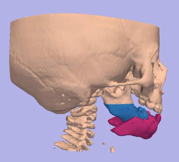
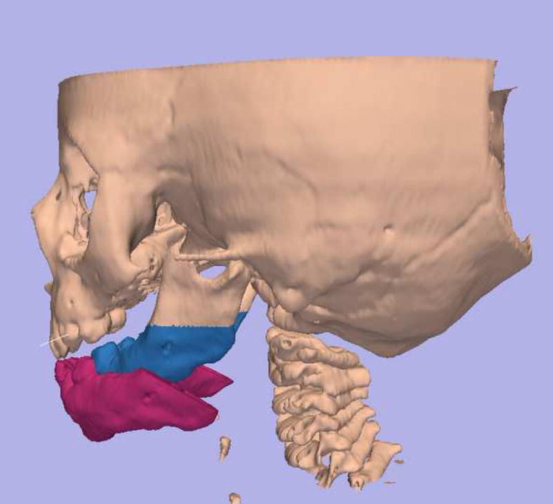
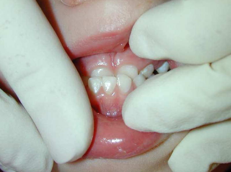
(A) Right and (B) left lateral 3-D virtual models (patient in Figure 9) constructed on Osteoplan™ with planned advancement and counterclockwise rotation to be achieved by curvilinear distraction. (C) End-distraction 3-D CT demonstrating achieved movement corresponding to prediction. (D) Frontal, (E) lateral and (F) intraoral views of patient at end-distraction.
Figure 11.

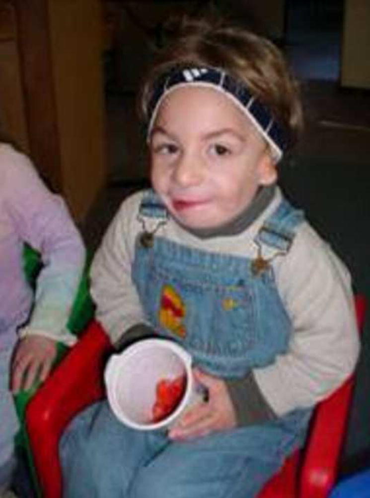
(A) Patient in Figures 9 and 10, 1 year after distraction and decannulated. (B) 2 years and (C) 3 years after distraction with no residual airway problems.
RESULTS
The sample consisted of 8 females and 5 males with a mean age of 11.9 years (range=15months–39 years). All patients underwent bilateral mandibular curvilinear distraction to obtain advancement and counterclockwise rotation. Eight of the 13 patients were 16 years or younger and 5 were less than 6 years of age. Diagnoses included Treacher Collins (n=3) and Nager (n=3) syndromes, craniofacial microsomia (n=2), retrognathia and open bite secondary to mandibular fractures and ankylosis (n=1), and micrognathia (syndromic, n=3; non-syndromic, n=1).
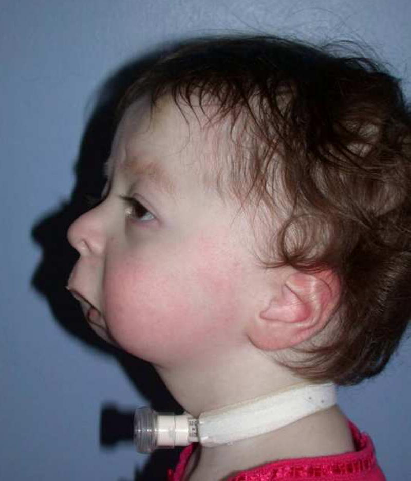
Distractor placement, vector of movement and the final mandibular position occurred along the correct axis and provided the predicted clinical result in 10 of the 13 patients (Figures 12–15). In the other 3 patients, distractor placement resulted in less than ideal jaw position. The devices were removed halfway through the fixation period, prior to complete bone formation. The desired jaw position was achieved by “molding” the regenerate and immobilizing the jaw until healing occurred. These 3 patients did not have the benefit of planning with the 3-D model and acrylic template that eliminated this problem in subsequent cases.
Figure 12.
(A) Frontal and (B) lateral views of a 2-year-old child with severe micrognathia who is tracheostomy dependent.
Figure 15.
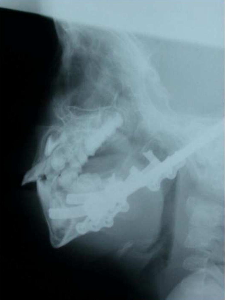
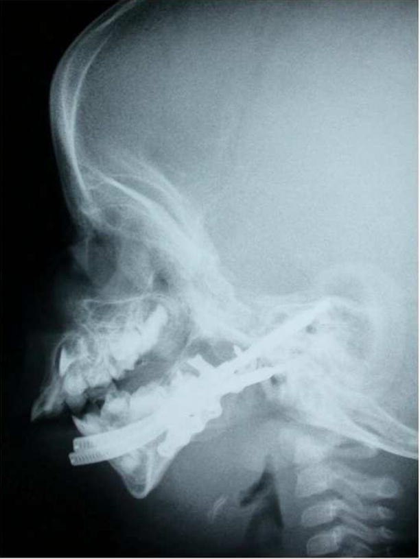
(A) Mid-distraction and (B) end distraction lateral cephalograms. Note the marked increase in posterior airway space.
In one patient, 1 of the devices failed after distraction was completed. During the fixation period, the device turned back on itself and the jaw position regressed. The device was activated again, correct jaw position achieved and the patient placed in maxillomandibular fixation until the gap filled in with bone. Analysis of the distractor revealed a malfunction of the stop that prevents spontaneous reversal of the device.
DISCUSSION
Standard distraction devices are propelled by screw-type mechanisms that move in only one plane of space. Hence, multi-dimensional movements are accomplished by constructing complex devices with multiple joints to achieve movement in each plane separately.10, 11 The distractors are large and cumbersome and, of necessity, must be placed extraorally. Inadequate planning and inaccurate skeletal movements have often resulted in poor occlusal and esthetic outcomes.12 Multivector, extraoral distraction devices may be difficult for the patient and surgeon to manage and errors often occur during active distraction. In this study, the concept and use of a fixed trajectory curvilinear distraction device to accomplish 3 dimensional mandibular movements were described and the results documented. The device is simple, easy to use and small enough to be implanted with only the activation rod being visible externally.
Our group previously demonstrated the feasibility of curvilinear distraction in a minipig model. The successful use of a semiburied, fixed-trajectory curvilinear distraction device requires accurate treatment planning. The treatment planning system (Slicer/Osteoplan™)4–7 accurately describes the arcs of rotation, radii of curvature, locations of the distraction devices and the orientation of osteotomies to achieve the proposed mandibular movements. In this study, we used custom curvilinear devices (Synthes CMF, West Chester, PA) as prescribed by the 3-D treatment planning system. However, we have also demonstrated, in a computer model, that there is a finite range of devices required to correct all mandibular deformities: radii of curvature 3, 4, 5, 7 cm and straight line.8 The prescriptions for the patients described in this paper conformed to these radii of curvature and confirmed the adequacy of this family of devices. Therefore, a custom device for each patient is not required.
Although the distractors used in this series of patients did not carry out movements in the horizontal plane (because there was no need for horizontal movement), this is possible using the curvilinear distractor design2. (Figure 16)
Figure 16.
(A & B) Prototype curvilinear device capable of horizontal movement.
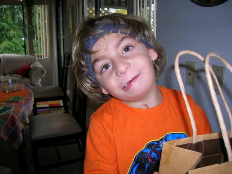
The indications for an operation in the 13 patients in this study were to advance and rotate the mandible in a counter-clockwise direction to achieve maximal chin advancement and to lengthen the ramus thereby increasing posterior face height. This movement also has a profound effect on posterior airway space. (Figures 4–15) Three of 4 patients dependent on a permanent tracheostomy for airway obstruction were successfully decannulated after distraction.
In the future, it will be possible to drive these miniature distraction devices by micromotors. They may also be totally buried, powered by batteries and remotely activated. We have demonstrated the use of a buried, automated, continuous distraction device in a minipig model and work is ongoing to modify and improve this device for use in humans.13, 14 We are conducting long-term outcome studies to document the efficacy and stability of curvilinear distraction osteogenesis as a technique for ramus lengthening and counterclockwise rotation and advancement of the mandible.
Figure 13.
Movement and Device Prescription calculated by software: Movement: ROC, 2.3 cm; elongation, 70mm. Distractors: ROC, 3.0 cm; elongation, 70mm.
Figure 14.
(A) Frontal and (B) lateral photographs of patient 10 months after distractors removed.
Acknowledgments
The authors would like to acknowledge the contributions made by Peter Everett and Lutz Ritter, research fellows in the Department of Oral and Maxillofacial Surgery (MGH) and the Harvard Surgical Planning Laboratory (Brigham & Women’s Hospital), in the development and testing of Slicer/Osteoplan™ for craniomaxillofacial surgical application.
This work was supported by grants from the AO-ASIF Foundation (Berne, Switzerland), Synthes CMF (West Chester, PA), the MGH Center for Innovation and Minimally Invasive Therapy in Medicine, the MGH Department of Oral and Maxillofacial Surgery Education and Research Fund and NIH grant P41RR13218 (R.K., PI)
Footnotes
Publisher's Disclaimer: This is a PDF file of an unedited manuscript that has been accepted for publication. As a service to our customers we are providing this early version of the manuscript. The manuscript will undergo copyediting, typesetting, and review of the resulting proof before it is published in its final citable form. Please note that during the production process errors may be discovered which could affect the content, and all legal disclaimers that apply to the journal pertain.
References
- 1.Trauner R. Kiefer-und Gesichtschirurgie. Urban & Schwarzenberg; Munchen-Berlin-Wien: 1973. [Google Scholar]
- 2.Seldin EB, Troulis MJ, Kaban LB. Evaluation of a semiburied fixed-trajectory curvilinear distraction device in an animal model. J Oral & Maxillofac Surg. 1999;57(12):1442–1446. doi: 10.1016/s0278-2391(99)90729-2. [DOI] [PubMed] [Google Scholar]
- 3.Schendel SA, Linck DW. Mandibular distraction osteogenesis by sagittal split osteotomy and intraoral curvilinear distraction. J Craniofac Surg. 2004;15:631–635. doi: 10.1097/00001665-200407000-00019. [DOI] [PubMed] [Google Scholar]
- 4.Everett PC, Seldin EB, Troulis M, Kaban LB, Kikinis R. A 3-D system for planning and simulating minimally-invasive distraction osteogenesis of the facial skeleton. In: Delp Sl, DiGioia AM, Jaramaz B., editors. MICCAI 2000. Proceedings of the 3rd International Conference on Medical Image Computing and Computer-Assisted Intervention; Pittsburgh, PA. New York: Springer-Verlag; 2000. Oct, pp. 1029–39. [Google Scholar]
- 5.Yeshwant K, Seldin EB, Kikinis R, Kaban LB. A computer-assisted approach to planning multidimensional distraction osteogenesis. Atlas Oral Maxillofac Surg Clin N Am. 2005;13:1–12. doi: 10.1016/j.cxom.2004.10.001. [DOI] [PubMed] [Google Scholar]
- 6.Troulis MJ, Everett P, Seldin EB, Kikinis R, Kaban LB. Three-dimensional treatment planning system based on computed tomographic data. Int J Oral Maxillofac Surg. 2002;31:349–357. doi: 10.1054/ijom.2002.0278. [DOI] [PubMed] [Google Scholar]
- 7.Yeshwant K, Seldin EB, Gateno J, Everett P, White CL, Kikinis R, Kaban LB, Troulis MJ. Analysis of skeletal movements in mandibular distraction osteogenesis. J Oral Maxillofac Surg. 2005;63:335–340. doi: 10.1016/j.joms.2004.06.057. [DOI] [PubMed] [Google Scholar]
- 8.Ritter L, Yeshwant K, Seldin EB, Kaban LB, Gateno J, Keeve E, Kikinis R, Troulis MJ. Range of curvilinear distraction devices required for treatment of mandibular deformities. J Oral Maxillofac Surg. 2006;64(2):259–264. doi: 10.1016/j.joms.2005.10.015. [DOI] [PubMed] [Google Scholar]
- 9.Kaban LB, Papadaki M, Goldwaser B, Seldin EB, McGill, John, Troulis MJ. Development of a buried, automated, continuous, curvilinear distraction device. 2006–2008 NIH Grant 2 R 44 DEO 14803-02. [Google Scholar]
- 10.Gateno J. Accuracy of stereolithographic templates for the installation of an external multiplanar distraction device. J Oral & Maxillofac Surg. 1999;57:96. [Google Scholar]
- 11.Gateno J, Teichgraber JF, Aguilar E. Distraction osteogenesis: a new surgical technique for use with the multiplanar mandibular distractor. Plast Reconstr Surg. 2000;105:833–888. doi: 10.1097/00006534-200003000-00009. [DOI] [PubMed] [Google Scholar]
- 12.Troulis MJ, Padwa B, Kaban LB. Distraction osteogenesis: Past, present and future. Facial Plast Surg. 1998;14:205–212. doi: 10.1055/s-2008-1064346. [DOI] [PubMed] [Google Scholar]
- 13.Magill J, Goldwaser B, Troulis MJ, Kaban LB. Skeletal expansion: An implant for distraction osteogenesis of the mandible. J Medical Devices. 2009 doi: 10.1115/1.3071969. (in press) [DOI] [PMC free article] [PubMed] [Google Scholar]
- 14.Goldwaser B, Magill J, Kaban LB, Troulis MJ. Novel device for automated continuous distraction osteogenesis: Preliminary results in a minipig model (Abs) J Oral & Maxillofac Surg. 2008;66(supp):38. [Google Scholar]


