Abstract
Transferrin (Tf) is an iron carrier protein that consists of two lobes, the N- and C-lobes, which can each bind a Fe3+ ion. Tf binds to its receptor (TfR), which mediates iron delivery to cells through an endocytotic pathway. Receptor binding facilitates iron release from the Tf C-lobe, but impedes iron release from the N-lobe. An atomic model of the Tf-TfR complex based on single particle electron microscopy (EM) indicated that receptor binding is indeed likely to hinder opening of the N-lobe, thus interfering with its iron release. The atomic model also suggested that the TfR stalks could form additional contacts with the Tf N-lobes, thus potentially further slowing down its iron release. Here, we show that the TfR stalks are unlikely to make strong interactions with the Tf N-lobes and that the stalks have no effect on iron release from the N-lobes of receptor-bound Tf.
Keywords: transferrin, transferrin receptor, receptor stalk, iron release, single particle electron microscopy
INTRODUCTION
Almost all living organisms depend on iron. However, the facile conversion between its ferrous (Fe2+) and ferric state (Fe3+), which makes iron an ideal co-factor for catalysis of redox reactions, also renders it very toxic. In the presence of oxygen, iron can catalyze the formation of hydroxyl radicals, which are a major cause for oxidative damage to proteins, DNA and lipids. In addition, ferric iron forms a highly insoluble hydroxide complex under physiological conditions, making it difficult for organisms to access iron. Transferrins (Tfs) have evolved as specific iron carrier proteins to control the toxic and insoluble characteristics of iron.
Tf molecules form a family of homologous proteins that share a closely related three-dimensional (3D) fold (reviewed in [1]). The Tf molecule consists of two homologous lobes, termed N- and C-lobe. Each lobe, in turn, consists of two domains (N1 and N2 and C1 and C2) that are connected by a flexible hinge, and each lobe can independently bind a Fe3+ ion. The highly specific binding site for Fe3+ is created when the two domains of a lobe close around the iron, whereas iron release requires the two domains to open up [2]. Diferric Tf in the circulation of vertebrates delivers iron to cells through an endocytotic pathway that involves the homodimeric transferrin receptor (TfR; reviewed in [3]). From the N terminus, TfR consists of a small cytoplasmic domain, a single transmembrane α-helix and a large ectodomain. The crystal structure of the ectodomain revealed the arrangement of its three structurally distinct domains, the protease-like, helical, and apical domains [4]. The ectodomain connects to the transmembrane domain through a 33-residue long stalk, which has no predicted secondary structure but contains two cysteine residues (Cys 89 and Cys 98) that form disulfide bonds between the two stalks of the dimeric receptor [5].
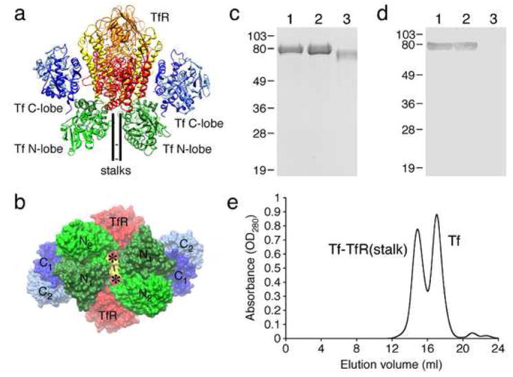
The structure of the Tf-TfR complex was elucidated by docking crystal structures of Tf and TfR into a density map of the complex at subnanometer resolution, which was obtained by single particle electron microscopy (EM) [6]. The model showed that in the complex the Tf N-lobe is sandwiched between the membrane and the TfR ectodomain and that the C-lobe abuts the receptor helical domain (Fig. 1a). Both domains of the Tf N-lobe make contact with the receptor, resulting in slower iron release from the N-lobe of receptor-bound Tf compared to free Tf at pH 7.4 [6]. Although the stalk was missing in the TfR construct that was used for single particle EM and iron release studies, the density map strongly suggested that the stalks would pass through a gap in between the N-lobes of the two receptor-bound Tf molecules (Fig. 1b). This finding prompted the hypothesis that the stalks may mediate additional contacts of TfR with the Tf N-lobes, thus further impeding the release of iron from the N-lobes of receptor-bound Tf [6].
Fig. 1.
The Tf-TfR(stalk) complex. (a) Atomic model of the Tf-TfR complex in ribbon representation (pdb id: 1SUV) based on a single particle EM reconstruction [6]. (b) Atomic model of the Tf-TfR complex in space filling representation showing the gap between the two Tf N-lobes through which the TfR stalks must pass. The asterisks indicate the putative positions of the TfR stalks and the lines the disulfide bridges between the two stalks. (c) 12.5% SDS PAGE gel of TfR(stalk) (lane 1), Tf-TfR(stalk) complex (lane 2), and stalk-less TfR (lane 3). (d) Western blot of the gel shown in (a) developed with anti-His antibody. (e) Elution profile from a size exclusion column showing two peaks corresponding to the Tf-TfR(stalk) complex and free Tf.
Here we present EM studies that support the notion that the TfR stalks pass through the gap between the two N-lobes of the receptor-bound Tf molecules, while spectroscopic studies show that the presence of the TfR stalks have no effect on the rate of iron release from N-lobes of receptor-bound Tf molecules.
MATERIALS AND METHODS
Protein expression and purification
Stalk-less TfR and its complex with Tf were prepared as described [6]. TfR(stalk) and its complex with Tf were prepared as described [7].
Monoferric Tf with iron loaded in the N-lobe (TfNFe) was prepared with lyophilized Tf (Boehringer-Mannheim) as described [8].
Samples were run on 12.5% SDS-PAGE gels and stained with Coomassie blue stain. His-tagged proteins were detected with anti-His antibody (GE Healthcare, Buckinghamshire, UK) and blots developed with the Sigma Fast system (Sigma-Aldrich, St. Louis, MO).
Electron microscopy and image processing
Negatively stained and vitrified specimens of stalk-less Tf-TfR complex were prepared as described [6]. Negatively stained samples of Tf-TfR(stalk) on lipid monolayers containing 2% Ni-NTA lipids were prepared as described [7].
20,483 particles were analyzed for negatively stained, stalk-less Tf-TfR complex on continuous carbon film and 9,381 particles were analyzed for negatively stained Tf-TfR(stalk) complex on Ni-NTA lipid monolayers. 53,753 particles were selected from specimens of vitrified Tf-TfR(stalk) complex. A 3D reconstruction was calculated with FREALIGN version 7.05 [9] using the atomic model of the Tf-TfR complex (pdb id: 1SUV; [6]) filtered to 30 Å resolution as the initial reference model. The final 3D density map included 32,308 particles and was filtered to 13 Å resolution, according to the Fourier shell correlation = 0.5 criterion [10]. Imaging and image processing details are provided in Supplementary Materials.
Iron release measurements
Iron release rates from free TfNFe, TfNFe bound to stalk-less TfR and TfR(stalk) were measured as described [11]. Iron release at pH 7.4 was measured in 50 mM HEPES, 100 mM NaCl, using 100 mM sodium pyrophosphate (PPi) as the iron-sequestering agent. Iron release at pH 5.6 was measured in 100 mM MES, 100 mM NaCl, using 5 mM PPi. Reactions were carried out with continuous stirring at 25°C. Iron release was initiated by adding 8 to 20 μl of 1 mg/ml protein to 2.2 ml of iron release buffer. Experimental details are provided in Supplementary Materials.
RESULTS
Formation of the Tf-TfR(stalk) complex
We generated a construct, which we will refer to as TfR(stalk), containing the ectodomain of the transferrin receptor (residues 89-760), the 33 residues–long stalk (residues 89-121), and an N-terminal 6xHis tag. TfR(stalk) was overexpressed in 293T cells and purified from the conditioned medium by Ni-affinity chromatography. On a Coomassie stained SDS PAGE gel, TfR(stalk) runs at an apparent molecular weight of about 80 kDa (Fig. 1c, lane 1) and is detected on a Western blot by anti-His antibody (Fig. 1d, lane 1). By comparison, a TfR ectodomain construct lacking the stalk and 6xHis tag runs at the lower apparent molecular weight of about 72 kDa (Fig. 1c, lane 3) and is not detected by Western blotting (Fig. 1d, lane 3). The difference in apparent molecular weight between the two constructs may be caused by the 39 extra residues of the stalk and 6xHis tag and the O-linked glycosylation of the stalk at Thr 104 [12].
The Tf-TfR(stalk) complex was formed by incubating TfR(stalk) with Tf at a molar ratio of 1:4 and removing excess Tf by size exclusion chromatography (Fig. 1e). Since the molecular weight of Tf and TfR(stalk) are both about 80 kDa, they are not resolved on a 12.5% SDS PAGE gel (Fig. 1c, lane 2).
Single particle EM of the Tf-TfR(stalk) complex
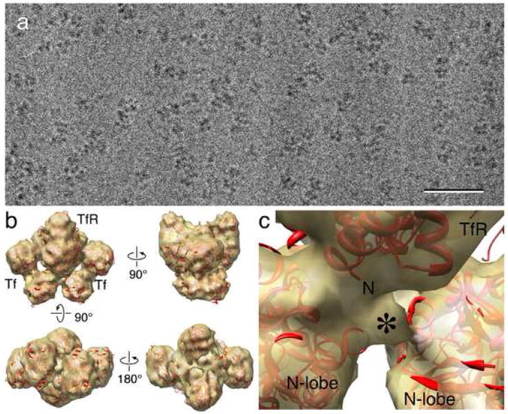
The Tf-TfR(stalk) complex was vitrified and imaged by cryo-EM (Fig. 2a). A density map at 13 Å resolution was calculated using 32,308 particles from 80 images (Fig. 2b, Supplementary Fig. 1). Some small additional density could be observed on the TfR ectodomain (asterisk in Fig. 2c), but a difference map calculated between the 3D reconstruction of the Tf-TfR(stalk) complex and the previously determined density map of the stalk-less complex [6] failed to reveal a clear difference peak representing the stalk (data not shown).
Fig. 2.
Cryo-electron microscopy of the Tf-TfR(stalk) complex. (a) Raw image of Tf-TfR(stalk) complex in vitrified ice. Scale bar is 50 nm. (b) Four views of the density map of the Tf-TfR(stalk) complex (gold) with the fit atomic model of the complex (red). (c) Close-up view of the density (asterisk) that may represent the beginning of the TfR stalk. The “N” indicates the beginning of the stalk-less construct used to determine the crystal structure of TfR.
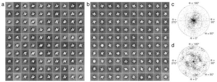
To verify that the stalk was indeed present, we adsorbed Tf-TfR(stalk) complex to a lipid monolayer containing Ni-NTA lipids. While the stalk-less Tf-TfR complex failed to bind to the lipid monolayer (data not shown), the Tf-TfR(stalk) complex was recruited with high efficiency, confirming the presence of the His-tagged stalk (Supplementary Fig. 2a). We selected 9,381 negatively stained particles from 56 images and classified them into 100 classes. Most of the class averages showed the top view of the Tf-TfR(stalk) complex (Fig. 3a), consistent with the model that the stalk passes through the gap between the two Tf N-lobes. A plot of the angular distribution confirmed the strong preference for the top view orientation (Fig. 3c). This angular distribution differs significantly from that seen with stalk-less Tf-TfR complex adsorbed to a continuous carbon film (Fig. 3d), which shows a preference for the side view orientation of the complex (Fig. 3b).
Fig. 3.
Negative stain EM of Tf complexes formed with TfR(stalk) and stalk-less TfR. (a) Class averages obtained by classifying 9381 particles into 100 classes showing predominantly top views of the His-tagged Tf-TfR(stalk) complex adsorbed to a lipid monolayer containing 2% Ni-NTA lipids. (b) Angular distribution plot showing the orientations of the His-tagged Tf-TfR(stalk) complex adsorbed to the lipid monolayer. (c) Class averages obtained by classifying 20,483 particles into 100 classes showing predominantly side views of the stalk-less Tf-TfR complex adsorbed to a continuous carbon film. (d) Angular distribution plot showing the orientations of the stalk-less Tf-TfR(stalk) complex adsorbed to carbon film. Note the difference in the angular distribution compared to panel c.
Kinetics of iron release from the N-lobe
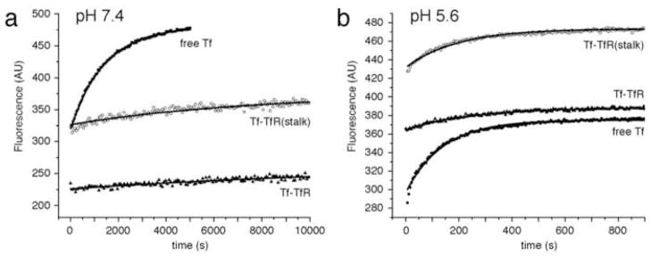
To investigate the effect of the TfR stalk on iron delivery, we used an established spectrofluorometric method [11] to measure rates of iron release from N-lobe loaded monoferric Tf (TfNFe) on its own, bound to stalk-less TfR, and bound to TfR(stalk). Iron release measurements were carried out at pH 7.4, corresponding to the extracellular pH (Fig. 4a), and pH 5.6, corresponding to the endosomal pH (Fig. 4b). The observed iron release rates (kobs) are summarized in Table 1.
Fig. 4.
Kinetics of iron release from the Tf N-lobe. (a) Iron release at pH 7.4 from the N-lobe of free TfNFe (squares), TfNFe bound to stalk-less TfR (triangles), and TfNFe bound to TfR(stalk) (circles). (b) Iron release at pH 5.6 from the N-lobe of free TfNFe (squares), TfNFe bound to stalk-less TfR (triangles), and TfNFe bound to TfR(stalk) (circles). Each condition was repeated three times with two different preparations. The data points represent an individual experiment, while the lines show the fitted curves to all six experiments performed for each condition.
Table 1.
First order rate constants for iron release from Tf N-lobe to pyrophosphate
| Tf species | kobs (× 103 s−1) | |
|---|---|---|
| pH 7.4 | TfNFe | 0.76 ± 0.06 |
| TfNFe-TfR | 0.07 ± 0.01 | |
| TfNFe-TfR(stalk) | 0.11 ± 0.03 | |
| pH 5.6 | TfNFe | 12.3 ± 1.1 |
| TfNFe-TfR | 4.0 ± 0.4 | |
| TfNFe-TfR(stalk) | 5.9 ± 0.8 |
Pyrophosphate concentrations were 100 mM at pH 7.4 and 5 mM at pH 5.6.
The numbers show the mean values and standard deviations.
At pH 7.4, the rate of iron release from free TfNFe was nearly 8 times faster (0.76 ± 0.06 × 10³ s−1) than from receptor-bound TfNFe. The rates of iron release from TfNFe bound to stalk-less TfR (0.07 ± 0.01 × 10³ s−1) and TfR(stalk) (0.11 ± 0.03 × 10³ s−1) were not significantly different, demonstrating that the TfR stalk does not affect iron release from the Tf N-lobe. All the iron release rates at pH 7.4 were slow. Iron release from free TfNFe was completed in 5,000 seconds, while it took twice as long to complete iron release from receptor-bound TfNFe. Raising the pyrophosphate concentration from 5 mM to 250 mM did not accelerate iron release (data not shown).
At pH 5.6, iron release from TfNFe was significantly faster than at pH 7.4. For all conditions dissociation of iron from TfNFe was completed within 600 seconds. The rates of iron release from TfNFe bound to stalk-less TfR (4.0 ± 0.4 × 10³ s−1) and TfR(stalk) (5.9 ± 0.8 × 10³ s−1) were again not significantly different. In contrast, the free TfNFe released iron about twice as fast (12.3 ± 1.1 × 10³ s−1) compared to receptor-bound TfNFe.
DISCUSSION
One of the unresolved questions in TfR-mediated iron delivery concerns the influence of the receptor on iron release from the two Tf lobes. Free in solution, the N-lobe releases iron at pH 5.6 much more quickly than the C-lobe [13], but mostly the N-lobe was loaded with iron in Tf molecules isolated from blood serum, showing that in vivo iron is predominantly released from the C-lobe [14, 15]. Further in vitro studies revealed that TfR is responsible for switching iron release from the N-lobe of free Tf to the C-lobe of receptor-bound Tf in acidified endosomes [16]. Our previous single particle EM work on the Tf-TfR complex provided a potential structural explanation for this switch. The pseudo-atomic model of the complex showed that the receptor interacts with both domains of the N-lobe, thus interfering with the opening of the lobe required for iron release [6]. Iron release measurements corroborated this conclusion, as iron release from the N-lobe of receptor-bound Tf was about four times slower than from the N-lobe of free Tf [6]. The density map further suggested that the stalks, which were lacking in the TfR construct used for the EM studies, would pass through a gap between the two bound N-lobes, possibly making additional contacts and further interfering with iron release from the N-lobes.
The iron release measurements presented in this study suggest that at pH 7.4 binding to a stalk-less receptor construct slows iron release from the Tf N-lobe by a factor of seven (Fig. 4a, Table 1), slightly more than the previously reported decrease by a factor of four [6]. The difference in the measured iron release rates in the two studies is likely due to differences in instrumentation and experimental set-up. The presence of the receptor stalks did, however, not result in a further decrease in the iron release rate from the N-lobe of receptor-bound Tf (Fig. 4a, Table 1). We repeated the measurements at pH 5.6, the pH of the endosome, where the Tf-TfR complex releases iron in vivo. The results showed that at this pH, receptor binding also slows iron release from the N-lobe, although only by a factor of two, while the presence of the receptor stalks again had no further effect (Fig. 4b, Table 1). Our studies demonstrate that receptor binding slows iron release from the Tf N-lobe at the extracellular pH of 7.4, thus helping to prevent undesired iron release from the Tf-TfR complex outside cells. In addition, although to a much lesser extent, receptor binding also slows iron release from the Tf N-lobe at the endosomal pH of 5.6, thus making some contribution to the switch of iron release from the N-lobe in free Tf to iron release predominantly from the C-lobe in receptor-bound Tf. At the same time, our studies reveal that the receptor stalks have no significant influence on iron release from the N-lobes of receptor-bound Tf molecules.
Compared to the previous density map of the complex formed by Tf with stalkless TfR [6], our single particle EM reconstruction of the Tf-TfR(stalk) complex showed some extra density at the expected position for the beginning of the stalk on TfR (Fig. 2c). From that point, the density faded out very quickly, and no significant density representing the stalk could be detected in a difference map between the density maps of Tf in complex with TfR(stalk) and stalk-less TfR. Despite its suggestive position, we thus have no firm evidence that the small additional density indeed represents the beginnings of the TfR stalks. To confirm the presence of the His-tagged stalk, we adsorbed the Tf-TfR(stalk) to a lipid monolayer containing Ni-NTA lipid. Since we could only see particles adsorbed to the monolayer when we used Tf-TfR(stalk) (Supplementary Fig. 2a) but not when we used stalk-less Tf-TfR, which lacks a His tag, we conclude that the stalk was present in the complex. Moreover, the class averages of Tf-TfR(stalk) adsorbed to lipid monolayer showed predominantly top views of the complex (Fig. 3a), different from the class averages of stalk-less Tf-TfR complexes adsorbed to a continuous carbon grid, which showed mostly side views of the complex (Fig. 3b). The different preferred orientations of the Tf-TfR(stalk) complex on monolayer and the stalk-less Tf-TfR complex on continuous carbon is also seen in the angular distribution plots (compare Fig. 3c with Fig. 3d). The preferred orientation of the Tf-TfR(stalk) complex with respect to the lipid monolayer is consistent with the proposed model (Fig. 1a), in which the receptor stalks pass through a gap in between the N-lobes of the two bound Tf molecules (Fig. 1b). The fact that we are unable to visualize the receptor stalks is consistent with their lack in predicted secondary structure and suggests that they do not adopt a defined conformation with respect to the remaining complex. It also indicates that the stalks do not engage in strong interactions with the Tf N-lobes, which would explain why they do not have any effect on iron release from the receptor-bound N-lobes (Fig. 4, Table 1).
Taken together, our iron release measurements and single particle EM studies suggest that the TfR stalks only serve to create a sufficiently large gap between the membrane and the TfR ectodomain to allow Tf molecules to bind to the receptor, but that they do not play a significant role in iron release from the Tf-TfR complex.
Supplementary Material
Acknowledgments
The authors would like to thank Philip Aisen and Olga Zak for advice and guidance on iron release measurements. This work was supported by NIH grant PO1 GM062580 (to Stephen C. Harrison). T.W. is an investigator of the Howard Hughes Medical Institute.
Footnotes
Publisher's Disclaimer: This is a PDF file of an unedited manuscript that has been accepted for publication. As a service to our customers we are providing this early version of the manuscript. The manuscript will undergo copyediting, typesetting, and review of the resulting proof before it is published in its final citable form. Please note that during the production process errors may be discovered which could affect the content, and all legal disclaimers that apply to the journal pertain.
References
- 1.Baker EN. Structure and reactivity of transferrins. Adv Inorg Chem. 1994;41:389–463. [Google Scholar]
- 2.Baker HM, Anderson BF, Baker EN. Dealing with iron: common structural principles in proteins that transport iron and heme. Proc Natl Acad Sci U S A. 2003;100:3579–3583. doi: 10.1073/pnas.0637295100. [DOI] [PMC free article] [PubMed] [Google Scholar]
- 3.Aisen P. Transferrin receptor 1. Int J Biochem Cell Biol. 2004;36:2137–2143. doi: 10.1016/j.biocel.2004.02.007. [DOI] [PubMed] [Google Scholar]
- 4.Lawrence CM, Ray S, Babyonyshev M, Galluser R, Borhani DW, Harrison SC. Crystal structure of the ectodomain of human transferrin receptor. Science. 1999;286:779–782. doi: 10.1126/science.286.5440.779. [DOI] [PubMed] [Google Scholar]
- 5.Jing SQ, Trowbridge IS. Identification of the intermolecular disulfide bonds of the human transferrin receptor and its lipid-attachment site. EMBO J. 1987;6:327–331. doi: 10.1002/j.1460-2075.1987.tb04758.x. [DOI] [PMC free article] [PubMed] [Google Scholar]
- 6.Cheng Y, Zak O, Aisen P, Harrison SC, Walz T. Structure of the human transferrin receptor-transferrin complex. Cell. 2004;116:565–576. doi: 10.1016/s0092-8674(04)00130-8. [DOI] [PubMed] [Google Scholar]
- 7.Kelly DF, Dukovski D, Walz T. Monolayer purification – a rapid method for isolating protein complexes for single particle electron microscopy. Proc Natl Acad Sci U S A. 2008;105:4703–4708. doi: 10.1073/pnas.0800867105. [DOI] [PMC free article] [PubMed] [Google Scholar]
- 8.Baldwin DA, de Sousa DM. The effect of salts on the kinetics of iron release from N-terminal and C-terminal monoferric transferrins. Biochem Biophys Res Commun. 1981;99:1101–1107. doi: 10.1016/0006-291x(81)90732-4. [DOI] [PubMed] [Google Scholar]
- 9.Grigorieff N. FREALIGN: high-resolution refinement of single particle structures. J Struct Biol. 2007;157:117–125. doi: 10.1016/j.jsb.2006.05.004. [DOI] [PubMed] [Google Scholar]
- 10.Böttcher B, Wynne SA, Crowther RA. Determination of the fold of the core protein of hepatitis B virus by electron cryomicroscopy. Nature. 1997;386:88–91. doi: 10.1038/386088a0. [DOI] [PubMed] [Google Scholar]
- 11.Egan TJ, Zak O, Aisen P. The anion requirement for iron release from transferrin is preserved in the receptor-transferrin complex. Biochemistry. 1993;32:8162–8167. doi: 10.1021/bi00083a016. [DOI] [PubMed] [Google Scholar]
- 12.Rutledge EA, Root BJ, Lucas JJ, Enns CA. Elimination of the O-linked glycosylation site at Thr 104 results in the generation of a soluble human-transferrin receptor. Blood. 1994;83:580–586. [PubMed] [Google Scholar]
- 13.Bali PK, Aisen P. Receptor-modulated iron release from transferrin: differential effects on N- and C-terminal sites. Biochemistry. 1991;30:9947–9952. doi: 10.1021/bi00105a019. [DOI] [PubMed] [Google Scholar]
- 14.Leibman A, Aisen P. Distribution of iron between the binding sites of transferrin in serum: methods and results in normal human subjects. Blood. 1979;53:1058–1065. [PubMed] [Google Scholar]
- 15.Williams J, Moreton K. The distribution of iron between the metal-binding sites of transferrin in human serum. Biochem J. 1980;185:483–488. doi: 10.1042/bj1850483. [DOI] [PMC free article] [PubMed] [Google Scholar]
- 16.Zak O, Aisen P. Iron release from transferrin, its C-lobe, and their complexes with transferrin receptor: presence of N-lobe accelerates release from C-lobe at endosomal pH. Biochemistry. 2003;42:12330–12334. doi: 10.1021/bi034991f. [DOI] [PubMed] [Google Scholar]
Associated Data
This section collects any data citations, data availability statements, or supplementary materials included in this article.


