Abstract
Minimally invasive abdominal surgery (laparoscopy) results in superior patient outcomes compared to conventional open surgery. However, the difficulty of manipulating traditional laparoscopic tools from outside the body of the patient generally limits these benefits to patients undergoing relatively low complexity procedures. The use of tools that fit entirely inside the peritoneal cavity represents a novel approach to laparoscopic surgery. Our previous work demonstrated that miniature mobile and fixed-based in vivo robots using tethers for power and data transmission can successfully operate within the abdominal cavity. This paper describes the development of a modular wireless mobile platform for in vivo sensing and manipulation applications. Design details and results of ex vivo and in vivo tests of robots with biopsy grasper, staple/clamp, video, and physiological sensor payloads are presented. These types of self-contained surgical devices are significantly more transportable and lower in cost than current robotic surgical assistants. They could ultimately be carried and deployed by non-medical personnel at the site of an injury to allow a remotely located surgeon to provide critical first response medical intervention irrespective of the location of the patient.
Keywords: in vivo, mobile, robots, sensors, surgery, wireless
I. Introduction
Laparoscopy is minimally invasive surgery performed in the abdominal cavity with long, slender tools that are inserted through small tool ports (trocars) placed in the abdominal wall of the patient. Laparoscopic procedures result in improved patient outcomes compared to conventional open surgical procedures [1]-[3]. Although laparoscopy has been overwhelmingly adopted for relatively simple procedures (e.g., gallbladder removal), it has seen limited application to more complex ones. This is principally because current tools and approaches impose significant constraints on the surgeon that result in severe ergonomic limitations, reduced dexterity, and limited perception [4], [5].
Robotic surgical tools have removed some of the limitations and reduced complications associated with traditional manual laparoscopy. Advantages of robots such as the da Vinci Surgical System include tremor reduction, additional articulations in surgical instruments, stereoscopic vision, corrections for motion reversal, and motion scaling [6]-[8]. However, these robots are all situated outside the patient and thus remain subject to the dexterity limitations imposed by the use of long tools inserted through small incisions. Most studies suggest that current externally-situated robotic systems offer little or no improvement over standard laparoscopic instruments in the performance of basic skills [9], [10]. Furthermore, da Vinci is expensive, cumbersome, tool changes are difficult [1], [11], and significant set-up time and operational space are required [12]. Many current efforts are focused on developing new robots and tools that improve mobility and sensing capability while reducing complexity and cost [13]-[17].
Other work is focused on developing robots in which all or most of the device enters the body. The simplest mechanisms have been maneuverable endoscopes for colonoscopy and laparoscopy [18], [19]. Some in vivo robots have been developed that apply radial pressure to the walls of hollow cavities, allowing them to explore organs such as the colon or esophagus [20]-[22]. Others employ a suction-based drive to move across the surface of a beating heart [23], [24], or are affixed to the inside of the abdominal wall to provide visual feedback [25], [26]. Another approach is an untethered pill that is swallowed and returns thousands of images as it passively moves through the gastrointestinal (GI) tract [27]-[30]. Similar devices with active locomotion or clamping systems are currently under development [31]-[33].
An alternative approach for robotic surgical systems involves placing miniature robotic assistants entirely inside the abdominal cavity of the patient. The use of in vivo robots that can be inserted through a small incision and fit entirely within the peritoneal cavity represents a novel approach to laparoscopic surgery. The in vivo robots described above require narrow cavities or natural processes for their mobility systems to function, and/or external connections for actuation, power, and tool control. The open environment of an insufflated abdomen during laparoscopic surgery is incompatible with most of these approaches.
Our previous work focused on developing a family of in vivo fixed-base and mobile robots that can successfully operate within the abdominal cavity. All of these robots relied on tethers for power, control, and data transmission, and each robot was wholly designed for a specific task. They have been used to enhance the ability of laparoscopic surgeons to visualize the surgical field [34], [35], and to obtain tissue samples during a single-port liver biopsy in a porcine model [36]. They were also used in the first application of miniature in vivo robotics to support laparoscopic urological surgery [37]. This latter study was the first use of these in vivo robots by surgeons and researchers not associated with their development. During the course of two radical prostatectomy and nephrectomy canine procedures, the surgeons found that the in vivo robots improved performance by providing additional views of the operative field without being limited by a fixed port position at the abdominal wall. However, several significant shortcomings of the robots were identified, including operational interference caused by the tether, and the lack of manipulation and sensor capabilities.
This paper presents our current progress towards developing wireless, modular in vivo robots that can provide vision, sensory, and task assistance during laparoscopic surgery. We include design details and results of ex vivo and in vivo tests of modular wireless wheeled robots with biopsy grasper, stapler and clamp, video camera, and physiological sensor payloads. A modular design approach facilitates rapid development of different payload capabilities without altering the power and control portion of the mobile platform. The ability to control and communicate with the robots without physical connections for power or bi-directional data telemetry enables a surgeon to arbitrarily relocate the robots within the abdominal cavity without interference from one another. Moreover, multiple robots can be introduced through one incision, thereby making possible single-port surgical procedures. They also have the potential to be field-configurable for specific applications.
II. ROBOT DESIGN
The general design of the wireless in vivo mobile robotic platform builds upon our earlier work developing tethered robots [36], [38], [39]. It consists of a cylindrical inner housing, two wheels that slip over the housing, and a tail that can be collapsed into the wheel treads when the robot is inserted or retracted through a trocar. The wheels allow for forward, reverse and turning motions, and the tail prevents counter rotation of the robot body when the wheels are turning. Depending on the modular payload, the tail can be as simple as a stainless steel coiled spring. In the case of a biopsy grasper arm or other payload that protrudes perpendicularly from the body, the payload arm itself can function as a tail.
A. Robot Base Design
The construction of the robot inner housing differs in several significant ways compared to previous efforts. The housing itself is modular, consisting of two halves with each half comprised of two clamshell-like pieces with a semi-circular profile. Stereolithography prototyping techniques are used to manufacture the housing components out of ultraviolet-cured (UV-cured) PolyJet FC720 Clear 83D. The housing components are assembled using UV-cured adhesive and mechanical fasteners.
Each half of the inner housing has a specific purpose. One half of the body houses the power plant (i.e., battery), the master control microprocessor and radio frequency (RF) communication electronics, and a permanent magnet direct current wheel motor. The second half of the body also houses a wheel motor, but the majority of the volume is a dedicated payload space. This design approach provides for a common mobile platform that can be easily re-configured for a variety of task specific applications.
B. Wheel Design
We have previously explored the nature of wheel-tissue interactions through analytical modeling, empirical analysis of experimental tests, and numerical finite element analysis [36], [38], [39]. This work provides a basis for understanding how changes in robot mass and wheel geometry affect robot mobility, and was used to design wheels for the current application. These wheels are 20 mm in diameter with 9 helical grousers arranged in a corkscrew pattern. The grousers are 1.5 mm deep, 1.75 mm thick, and are spaced at 7 mm intervals. The pitch angle is 10.6° so that a minimum of two grousers are in surface contact at all times to ensure a smooth motion profile. The wheels are bored to accommodate the robot body housing and have an inside diameter of 16.25 mm with a wall thickness of 0.375 mm. The grouser treads provide additional mechanical support to the thin walls. At the end of each wheel is a small ball-like feature that facilitates handling of the robot by the surgical team using laparoscopic tools during insertion and retraction. The wheels are manufactured using the same stereolithography techniques and materials as used for the robot body housing.
Each wheel is actuated by a 6 mm diameter permanent magnet direct current (PMDC) motor with a 256:1 gear ratio manufactured by MicroMo. A spur gear on the motor shaft couples the motor to a spur gear and bearing assembly mounted on the end of each wheel. A schematic and exploded view of the robot platform is shown in Fig. 1.
Fig. 1.
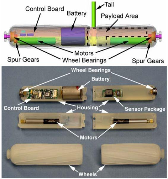
Schematic of wireless modular robot platform (top), and exploded view of an as-built robot (bottom).
C. Electronics and Communications
The robot master control circuit board is a custom designed double-sided surface mount printed circuit board that incorporates a RF transceiver, a multi-channel motor driver integrated circuit (IC), and a master microprocessor control unit (MCU). The communication unit is built around a Nordic nRF2401A 2.4 GHz ISM band single-chip radio transceiver. This low-power, fully-integrated transceiver is capable of error-checked data rates up to 1 Mbps in burst mode. Because there are 125 receive/transmit channels, multiple robots can be used simultaneously without interfering with one another. The transceiver is configured using a 3-wire serial interface to the control board MCU. A differential to single-ended matching network based on the Nordic nRF2401 reference design is used to accommodate a single-ended connection to a 50 Ohm chip antenna (LINX ANT-2.45-CHP).
A Toshiba TB6557FLG motor driver IC is used to provide up to six H-bridge (two constant current-controlled and four voltage-controlled) output drivers. This IC is also configured using a 3-wire serial interface to the MCU. Two of the voltage-controlled outputs are generally dedicated to controlling the PMDC wheel motors. A third voltage-controlled output is used in the biopsy, staple, and clamping robots to drive the tool motor. Other types of actuators and components can be accommodated with the current design. For example, it is anticipated that the constant current-controlled outputs will be used in a future robot to control a voice coil actuator as part of an adjustable focus camera system.
The master MCU is a PIC16LF767. This low-power processor includes a 10-bit analog-to-digital converter with up to 11 input channels, three independent pulse width modulation modules, and extensive power management features that can minimize power requirements. In its current configuration the processor operates at 4 MHz, although a variety of lower or higher frequencies can be used. The MCU is responsible for configuring the various robot peripherals (e.g., transceiver and driver IC), reading sensor data, controlling actuators, data transfer, and other housekeeping tasks.
All on-board power is provided by a single high power 185 mAh lithium organic cell battery (Tadiran TLM-1520MP). This battery has sufficient energy density to operate the robot for at least 2 hours with all motors running continuously. A stationary sensor robot will operate for 4 hours. A typical laparoscopic cholecystectomy takes 30-45 minutes; a laparoscopic liver biopsy requires significantly less time. The current robot therefore has sufficient energy reserves to support or perform these most common procedures.
External control systems have also been developed to send control commands to the robot and process the in vivo data telemetry stream. These systems incorporate the same microprocessors and RF transceivers as the in vivo robots. Additional components are included as human interface devices (e.g., joysticks to control the robot wheels), and the MCU software is modified to reflect these differences.
D. Ceiling Pan/Tilt (CPT) Robot Design
A robotic platform that could be magnetically attached to the inside of the abdominal wall was also created (Fig. 2). This robot contains a color CMOS imager and LED lighting payload that provides visual feedback from the operating field. The CPT design replaces the two wheels used for the mobile robot with a single outer cylindrical housing supported by bearings at both ends. This outer housing also incorporates a viewing slot for the camera and LEDs, and magnetic end caps to provide for attachment to an external magnetic handle. The magnetic attachment mechanism allows the surgeon to pan the in vivo camera by sliding the handle across the abdominal wall of the patient. A PMDC motor and spur gear combination in the robot allows the inner robot housing body containing the camera payload to rotate (tilt) relative to the outer housing.
Fig. 2.
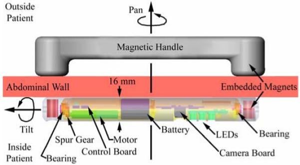
Schematic of Ceiling Pan and Tilt (CPT) module.
III. MODULAR PAYLOAD DESIGN
A. Biopsy Grasper and Actuator
Traditional cable-operated laparoscopic biopsy grasper jaws do not overlap or completely sever tissue. Consequently, laparoscopic biopsies are typically “grasp and tear” procedures that require a relatively large amount of force to tear the sample away from the organ. Because the motors used to actuate the in vivo robots cannot directly generate sufficient forces to do this, we developed an actuation mechanism with a large mechanical advantage that would sever the tissue.
A number of alternative biopsy designs were developed and tested. As previously described [36], early design efforts used a PMDC motor slider mechanism to actuate a set of standard laparoscopic biopsy graspers. This attempt to replicate the laparoscopic “grasp and tear” biopsy procedure yielded inconsistent results because the mobile platform lacked sufficient traction to routinely and reliably tear the partially severed sample from the main tissue body. Other early design approaches included using a four-bladed mechanism similar to a tree spade to extract a tissue sample, and a garage door-type mechanism that would close over and slice a sample from a protruding edge of tissue. Both approaches were limited by frictional forces that impeded the motion of the blades. Another concept used a flat sliding blade to cut a sample from tissue that had been sucked into a reservoir using a vacuum. Drawbacks to this approach included generating sufficient suction forces and proper placement of the robot for sampling. Finally, a grasper arm with a Nitinol blade was developed. While this approach worked moderately well, it was difficult to sharpen the blade and the Nitinol did not hold an edge well, making it difficult to routinely sever a specimen completely.
Following a lengthy series of bench top tests, a promising preliminary general mechanism design was identified (Fig. 3). The prototype biopsy grasper resembles a jaw. Unlike other laparoscopic biopsy forceps in which both jaws are hinged about a pivot point, only one jaw of the robotic grasper moves during sampling. The lower jaw remains stationary and provides a rigid and stable base against which the upper jaw can cut. In addition to providing a large mechanical advantage, this design can accommodate storing multiple tissue samples and, with small changes, can be used with a variety of other end-effectors (e.g., a clamp to hold tissue and/or control hemorrhaging).
Fig. 3.
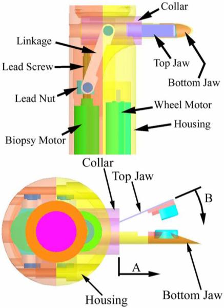
Schematic of the in vivo biopsy grasper - top view (top) and side view (bottom).
The upper jaw is constructed out of a super-elastic shape-memory nickel titanium alloy (Nitinol) ribbon (Memry Corporation) 0.25 mm thick and 3 mm wide. It is profiled such that the grasper is normally open. A wide variety of profiles can be achieved by heat-treating the ribbon for approximately 10 minutes at 500 °C, followed by quenching in water. The Nitinol ribbon is glued to a fixed nylon rod insert that fits inside the bottom jaw. The nylon rod is also glued to the housing of the robot, which anchors the grasper when the collar is actuated. The fixed bottom jaw is constructed from a hypodermic medical stainless steel tube and it forms a reservoir for storing multiple samples. The blades of the grasper are approximately 1.5 mm long segments cut from sharpened titanium nitrate-coated stainless steel tubes. They are glued to small plastic inserts fixed to the top and bottom jaws. The bottom blade has a circular profile with a diameter of 3 mm. The semi-circular top blade is 3.8 mm in diameter and overlaps the bottom blade when the jaw is closed.
A tissue sample is obtained by using a PMDC motor to actuate a collar that slides over the grasper (direction A in Fig. 3). As the top jaw closes (direction B), the upper and lower cutting surfaces overlap and sever the tissue sample. When implemented on a robot, the biopsy arm is perpendicular to the robot body and actuator motor. Therefore, an actuation linkage inspired by our previous work [36] is used to transform the direction of translation of a lead nut driven by the motor to an axis inline with the movement of the collar. The limit of translation of the lead nut is such that the linkage approaches a mechanical singularity at the point of grasper closure, producing a large mechanical advantage.
Biopsy grasper arms based on variations (e.g., different jaw lengths, opening angles, profiles) of the preliminary design were constructed and tested using a bench top jig. The principal goal was to investigate the effects of different grasper profiles and lengths on the forces required to actuate the mechanism. Each complete test consisted of 50 actuations of the candidate biopsy graspers, starting with the graspers completely open and finishing with them completely closed. A load cell measured the axial force in the nylon supporting rod as the motor and lead screw linkage were used to slide the grasper collar over the jaws. Force data were recorded at a rate of 20 Hz during each actuation.
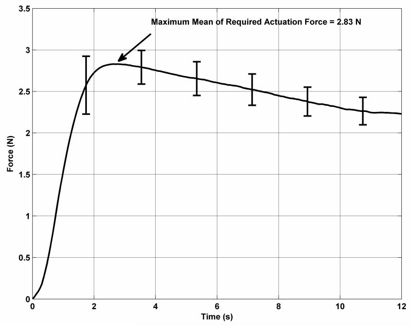
The results of these tests were used to develop a final candidate grasper arm design. This grasper is approximately 14 mm long with a profile angle of 30°. The top cutting blade protrudes 2 mm from the top jaw and is mounted at a slight angle so that it closes tightly over the bottom blade. The bottom blade is 1 mm long. Mean results from the required force test for this grasper are shown in Fig. 4. The error bars indicate the standard deviation in the measured forces at intervals of approximately 1.8 seconds. The maximum required actuation force of 2.83 N occurs at the very start of the motion of the collar as it overcomes static friction and begins flexing the top jaw of the grasper. The force decreases with time as the contact point between the collar and the top jaw moves farther away from the anchor point.
Fig. 4.
Required actuation forces for the biopsy grasper.
Following the actuation force tests, the maximum force that could be applied by the actuation mechanism was determined by holding the collar fixed at various positions with the grasper jaws ranging between fully open and fully closed. At the start of actuation, with the biopsy grasper fully open, the maximum force that could be applied was 7.3 N. This is greater than twice the force required to begin to close the jaw. As the collar slides along the biopsy arm, the angle between the collar and the lead screw linkage decreases and the maximum applied force increases to approximately 13.2 N at the translation limit of the collar. During these tests, the motor was operated using a power supply with the same voltage (4 V) as the battery used to power the robot. The maximum stall current was approximately 400 mA, well below the peak current (2.5 A) that can be supplied by the battery.
B. Stapling and Clamping
With relatively small modifications, the basic design of the biopsy grasper and actuation mechanism can be used for other applications. As an example, a second mobile robot was developed that incorporated a stapling and clamping end effector in place of the biopsy grasper. The tip of the upper jaw of the biopsy arm was modified to accommodate a standard laparoscopic staple. The plastic inserts in the upper and lower jaws were modified to contain a channel for the staple. Once snapped into place, the staple is securely held within the jaws until the collar is actuated. When no staple is present this arm can also be used for applications requiring clamping and holding, such as applying pressure to a bleeding blood vessel or manipulating tissue. With the exception of these minor changes, the mobile robot is unchanged from the overall modular design described in Section III. The biopsy robot is shown in Fig. 5 (top). For comparison, the stapling/clamping robot is shown in Fig. 5 (bottom).
Fig. 5.
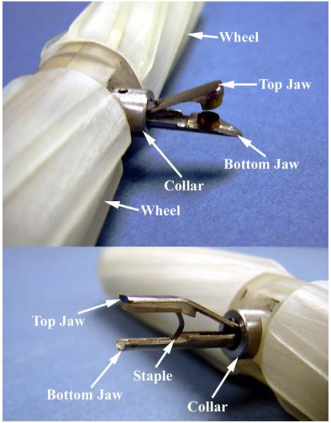
The in vivo biopsy grasper in the open configuration (top), and the stapler in a loaded configuration (bottom).
C. Sensing
During laparoscopic surgery the abdominal cavity is insufflated with CO2 to provide maneuvering space for tools and instruments. The temperature, pressure, and (sometimes) humidity of this gas are monitored only externally to the body, and local conditions can vary dramatically. It is important for patient health and well-being during surgery that stable conditions are maintained. Without local measurements of these parameters, the actual conditions can only be estimated.
An exploded view of a modular wireless mobile robot platform equipped with a physiological sensor payload is shown in Fig. 1 (bottom). This platform has been used to demonstrate the feasibility of in vivo sensory feedback. The sensor payload is a custom designed PCB currently configured to monitor temperature (T), pressure (P), and relative humidity (RH), although a variety of other sensors (e.g., pH, glucose level) can also be accommodated. The module also includes additional electrical components and circuitry for power management and conditioning, and requires connections to the master control board for only power and data communication.
Temperature and relative humidity are measured using a single chip sensor module (Sensirion SHT15). This chip provides a calibrated digital output for both T and RH via an on-board 14-bit analog to digital converter. The data are transferred to the master MCU via a 2-wire serial interface. Pressure is monitored using a Freescale Semiconductor absolute pressure sensor (MPXH6300A), which has a full range of 300 kPA, and a sensitivity of 16.2 mV/kPA. A charge pump (Microchip MCP1252) is used to boost the 3.0 V supplied by the master control board to the 5 V required by the sensor. Integrated on-chip conditioning networks provide a high output, temperature compensated signal, which is measured by the master MCU using its analog to digital converter.
D. Camera
The camera system payload developed for use in the CPT includes an MT9V125 color digital CMOS image sensor from Micron. This ¼-inch sensor has a 640×480 active pixel array with both NTSC and PAL analog composite video outputs. It also has numerous features that can be used to optimize image quality, such as color correction, automatic white and black balance, gamma correction, and color correction. A matched, multi-element Sunex lens (DSL758C) is used in a fixed-focus configuration that provides a depth of field of 4 cm to infinity. Illumination is provided by 5 mm diameter 20,000 mcd white LEDs (LED5 15DG). A diffuse illumination pattern was obtained by filing off the LED lens assembly from the body of the device. The video output from the camera system was transmitted to the operating room monitor using a small tether because a high quality miniature wireless video transmitter was unavailable. All power was provided by the on-board battery, and command and control data transmission was wireless.
IV. IN VIVO RESULTS
The in vivo performance of the robots was characterized in porcine models under an Institutional Animal Care and Use Committee approved protocol. The female swine is generally accepted as the best model for laparoscopic surgical training and testing because its internal anatomy and the size of the peritoneal cavity most closely resemble human anatomy.
A. Mobility
The ability of wireless robotic platforms to maneuver within the in vivo environment was first demonstrated by inserting two robots into the abdominal cavity (Fig. 6 top). One robot was equipped with a sensor payload, and the other with a biopsy grasper payload. Both robots successfully navigated throughout the abdominal cavity. They were able to traverse over and across all of the abdominal organs (e.g., liver, spleen, and bowel) without causing any visible tissue damage. Video recorded through a laparoscope was used to reconstruct the paths traversed by the robots, a portion of which is shown in Fig. 6 (bottom). Both robots were able to negotiate sharp turns within the confines of the abdominal cavity. This ability is facilitated by the fact that both wheels are independently driven, which allows the robots to turn in place.
Fig. 6.
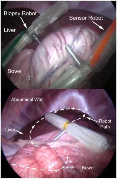
Multiple robots being controlled simultaneously in vivo during porcine testing (top), and in vivo path traced during porcine testing (bottom).
Multiple robots could be used at the same time because communication to and from each robot used different radio frequencies. Without interference from a tether, the robots were able to climb over one another as easily as they were able to climb over abdominal organs. The robots never became trapped by becoming stacked on top of one another. However, occasionally a robot could find itself stuck in areas such as an especially deep fold in the bowel, or under an organ that moved due to surgeon manipulation or repositioning of the animal. In these cases, the robot was extricated with a laparoscopic grasper tool that could grab the ball-like feature found on the end of each wheel.
B. Biopsy
The biopsy robot was used to sample hepatic tissue during the porcine surgery. The robot was driven up to the point of interest, and the biopsy grasper was then used to clamp onto the tissue while being entirely remotely controlled (Fig. 7 top). The actuation mechanism closed the jaws onto the sample, and the robot was then driven away from the sample site, separating the sample from the liver. Finally, the jaws were opened and the specimen was retrieved using a laparoscopic tool (Fig. 7 bottom). Several additional samples were collected to demonstrate device repeatability. These samples were collected from the jaws after the robot was removed from the in vivo environment. A typical multi-sample robotic biopsy procedure requires approximately 3 minutes for insertion and navigation to the biopsy site, 1-2 minutes to obtain each sample, and 2 minutes for retraction from the abdominal cavity. The total procedure required 12-15 minutes, well within the operational time provided by the on-board battery.
Fig. 7.
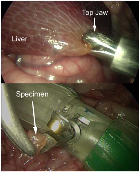
The in vivo biopsy robot sampling hepatic tissue.
C. Stapling and Clamping
The next test demonstrated the feasibility of in vivo robotic stapling and tissue manipulation. The stapling/clamping robot was first used to place a staple around a branch of the small intestine artery. Shortly after this, one of the PMDC motors failed and the robot was removed from the animal. The staple arm was then detached from the body of the robot and reinstalled on the body of the biopsy robot, which had previously been removed from the peritoneal cavity. This robot was then reinserted into the abdominal cavity of the animal and used for the remainder of the test. This entire process required less than 5 minutes and serendipitously demonstrated the value of a modular design and the potential for field configurability of these robots.
The reconfigured biopsy/staple robot was then used to grasp and clamp various tissues and organs within the peritoneal cavity. Fig. 8 shows the robot applying clamping pressure to a portion of the liver. Sufficient traction and grasping forces were generated to permit the robot to drag and reposition this portion of the liver during the test.
Fig. 8.
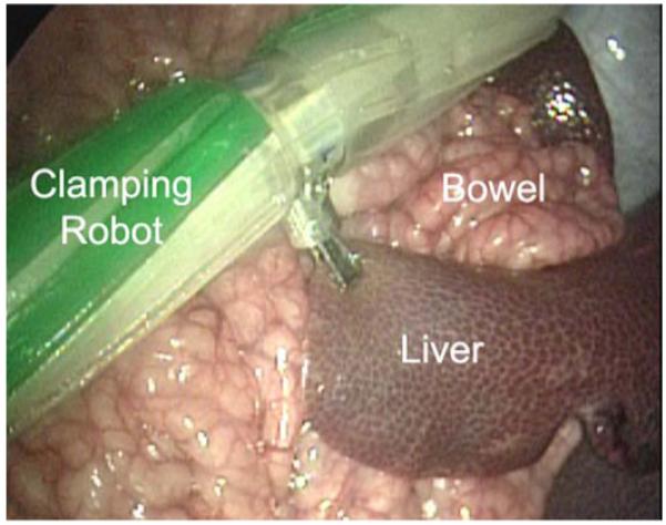
The in vivo stapling robot applying clamping pressure to the liver.
D. Camera
The CPT robot was tested in vivo in a porcine model to demonstrate vision assistance for the surgical team. After insertion the CPT was magnetically attached to the abdominal wall (Fig. 9 top). The surgical team controlled the video image by moving (panning) the external handle and by using the wireless control system to rotate (tilt) the inner housing relative to the outer housing. Illumination was provided solely by the onboard LEDs. The CPT provided visual feedback of the entire abdominal cavity and was particularly useful for following the motion of the sensor robot (Fig. 9 bottom).
Fig. 9.
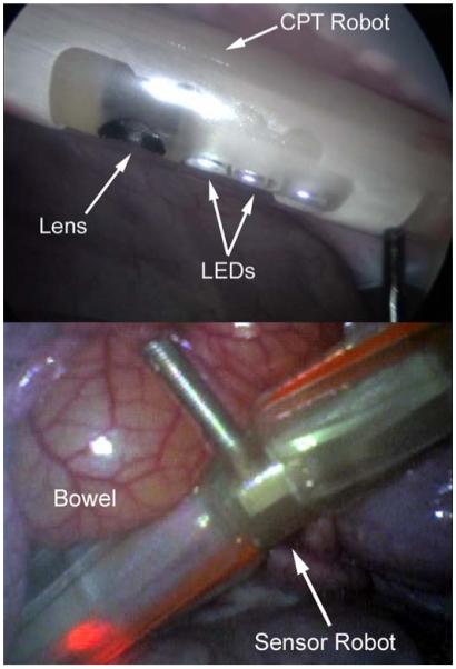
View of the CPT from the laparoscope (top) and a view from the CPT (bottom).
E. Telemetry and Sensing
The telemetry and sensor platforms have also been used in a series of in vivo tests in porcine models to evaluate overall system performance. The reliability of the telemetry system was first independently examined [40]. A master control circuit board (without the driver IC) and battery were mounted in a protective silicon tube and placed into an insufflated porcine abdominal cavity. An ex vivo transceiver board located approximately 5 m from the operating table was used to send commands to the in vivo transceiver at a rate of approximately 1 Hz. The in vivo device relayed the received commands to a second ex vivo receiver. The data arriving at the ex vivo receiver were recorded to monitor the reliability of transmitted commands to and from the peritoneal cavity.
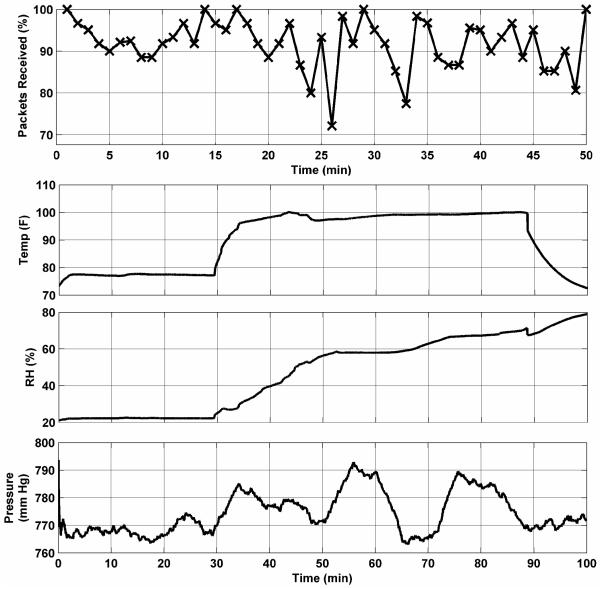
Fig. 10 (top) shows the percentage of packets successfully received in vivo during a 50-minute span. Approximately 90% of all packets were successfully received in vivo for the duration of this test. Reliability for in vivo to ex vivo transmission was approximately 85% during this same period. Similar results were obtained in subsequent tests.
Fig. 10.
Telemetry reliability from in vivo testing (top), and sensory data from in vivo testing (bottom).
In a separate test, a complete sensor module was integrated into the mobile robotic platform and the ability to monitor in vivo physiological parameters was evaluated. Fig. 10 (bottom) shows a typical plot of T, P, and RH variations. This telemetry was monitored and recorded at a workstation approximately 5 m from the operating table. The data clearly track significant events during the test. The temperature, initially indicating room temperature, shows a rapid rise upon insertion into the abdominal cavity. The pressure and relative humidity data also show increases corresponding to the conditions within the insufflated cavity. The insufflation pressure was cycled several times during the course of the test, and those fluctuations are also apparent in the recorded data stream. After approximately 88 minutes, the robot was removed from the abdominal cavity, and the temperature and pressure return to ex vivo conditions. The relative humidity, however, continues to increase. A small amount of fluid was later found trapped within the body of the robot, which explains the high ex vivo humidity reading.
Quantitative in vivo evaluation of properties such as transceiver antenna radiation patterns or tissue losses was not practical during development work or in the current context of a mobile telemetry platform. These properties depend upon many factors, including transceiver orientation and tissue composition. Real-time three-dimensional localization of the mobile platform within the peritoneal cavity was beyond the scope of this project. The effects of tissue losses vary widely depending upon factors such as tissue composition (e.g., fat, muscle, bone), layer thickness and geometry, and histological characteristics. The results presented in this work suggest that the current design is robust and capable of reliable transmission of data and control telemetry in the dynamic and varied environment of the in vivo abdominal cavity.
V. Discussion
In vivo mobility tests demonstrated the ability of the robotic platform to climb organs two to three times its own diameter as it navigated throughout the abdominal cavity. The size of the device did not appear to have a significant effect on its ability to maneuver within the confines of its environment. In the long-term, however, a smaller size is desirable even if only to facilitate its use with smaller standard trocars. The size of the current robots is currently driven by the size of the off-the-shelf internal components, particularly the battery. Past experience suggests that with some custom fabrication (e.g., circuit boards and electronic components) and a smaller battery (i.e., shorter operating time), a reduction in overall robot size of 20%-25% is possible.
The mobility tests also demonstrated that the robots could traverse internal organs without causing any visual tissue damage. This is consistent with the results of our previous studies. One of those studies [39] used finite element analysis to examine the relationship between induced tissue stress and robot characteristics (e.g., wheel design, robot mass). The maximum von Mises stress calculated for a robot similar in size and weight to those described in the current work was 2.2 kPa for a liver tissue model. This is significantly less than the stresses induced when surgeons handle tissue using traditional tools. During routine laparoscopic procedures, grasping forces as high as 40 N have been recorded [41], corresponding to a tissue pressure of approximately 400 kPa. This suggests that in vivo robot-induced tissue damage will be negligible compared to conventional procedures.
More recently, we conducted a series of survivable animal studies that clinically demonstrated that these types of in vivo robots can be used without causing organ or tissue damage [42]. Three porcine cholecystectomy procedures were performed using in vivo robots to provide surgical assistance. Following each procedure, the animal was transferred to a care facility and monitored for 14 days for signs of infection or other distress. At the end of the observation period, the animal was sacrificed and visual, tactile, and histopathological exams were conducted. No abnormalities, infections, tissue damage, or other complications were found in any of the animals.
The robots described in the current work were manufactured using stereolithography prototyping techniques to reduce development time. The biocompatibility of this material was not considered at this stage, nor were the resulting robots completely sealed. We would expect that in actual use devices such as these would be hermetically sealed and made of biocompatible material, as were the robots used in the survivable animal studies described above. Those robots, also based on original laboratory prototypes, were constructed using medical grade polycarbonate and ABS. Before they were used, the robots were sterilized using either ethylene oxide gas or the STERRAD Sterilization System. This prior work therefore also demonstrates the feasibility of creating robust, medically compatible in vivo robots based on prototypes such as those discussed in the current work.
VI. Conclusions
A modular wireless wheeled robot platform was designed that can accommodate various payload options to provide in vivo surgical vision and task assistance. The ability to rapidly develop and implement a variety of payloads was facilitated by taking a modular design approach that obviated the need for wholesale redesign of the entire robotic system for each unique application. The robot body consists of two distinct halves. One half is dedicated to the power plant and master control and communication electronics that are common to all robot variations. The second half has a payload bay that can hold a variety of sensing and/or mechanical components.
Several payload options were designed, tested, and incorporated into complete robots that were tested in vivo in a porcine model. A biopsy grasper and actuation mechanism payload provides the ability to obtain multiple tissue samples. The actuator and linkage mechanism provides 2-5 times the force required to close the grasper jaws. This actuator and linkage system was also incorporated into a stapling and clamping payload that can be used for applications such as control of bleeding or tissue manipulation. A physiological sensing payload was implemented to remotely monitor temperature, pressure and relative humidity levels within the abdominal cavity without requiring external connections.
The ability to control and communicate with the robots without requiring any physical connections for power or bi-directional data telemetry was demonstrated. The robots were able to navigate throughout the entire abdominal cavity without causing tissue damage. Multiple robots, each communicating on a unique frequency, could be used simultaneously without interfering with one another. The reliability of the wireless transmission link and the ability of the sensor payload to track in vivo environmental conditions were also tested and characterized.
Finally, a camera system and lighting payload was developed and incorporated into the modular robotic platform. The outer housing of this platform was modified to accommodate a magnetic attachment mechanism. This system was then magnetically attached to the inside of the abdominal wall of the animal and used to provide video feedback of the in vivo environment during the mobile robot tests.
Current work is focused on developing a robust model to describe the cutting of biological soft tissue because it is difficult to measure or characterize in vivo properties of tools or soft tissue on a consistent basis. Experiments can be done ex vivo or in vitro, but the material properties generally differ greatly from living tissue. There are also few, if any, detailed studies regarding the cutting and tearing procedures necessary to sever different types of biological tissue. The cutting model will be used to guide the development of more efficient end effectors for a variety of biological soft tissues.
Future work includes developing additional payload options. One goal is to integrate a sensor payload and a grasping manipulator onto a single wireless mobile platform that could be used for targeted therapeutic diagnoses and interventions. A second goal is to develop a flexible or retractable end effector arm so that these robots can be inserted into the abdominal cavity through standard size laparoscopic trocars. Implementation of a completely wireless, adjustable focus camera system is also ongoing.
A long-term goal of this work is to improve the feasibility of ultimately being able to provide emergency medical personnel in remote areas with the ability to deploy a cooperative team of robots with a variety of sensors and manipulators. Such wireless in vivo robotic surgical assistants could allow a surgeon to become a remote first responder irrespective of the location of the patient.
Acknowledgment
A portion of this work is derived from material previously published in the 2008 Proceedings of the ASME International Engineering Technical Conferences “Modular Wireless Wheeled In Vivo Surgical Robots,” by S. R. Platt, J. A. Hawks, M. E. Rentschler, L. Redden, S. Farritor and D. Oleynikov, ASME paper DETC2008-49157, and appears here with the permission of ASME. We thank Drs. D. Oleynikov and B. Varnell for their assistance during the in vivo tests.
Manuscript received October 3, 2008. This publication was made possible by Grant Number EB005663-01A1 from the National Institutes of Health. Its contents are solely the responsibility of the authors and do not necessarily represent the official views of the National Institute of Biomedical Imaging and Bioengineering or NIH.
Biography
 Stephen R. Platt received a B.A. degree in physics and astronomy from Williams College, Williamstown, Massachusetts in 1983, a M.S. degree in astronomy and astrophysics from the University of Chicago, Chicago, Illinois in 1984, a M.S. degree in mechanical engineering from the University of Nebraska-Lincoln, Lincoln, Nebraska in 2003, and a Ph.D degree in astronomy and astrophysics from the University of Chicago, Chicago, Illinois in 1991, where he was a Farr Research Fellow and a NASA Graduate Research Fellow.
He is currently a Research Associate Professor in the Department of Mechanical Science and Engineering at the University of Illinois at Urbana-Champaign, Illinois. Previously, he had been a Research Associate Professor in the Department of Mechanical Engineering at the University of Nebraska-Lincoln, Lincoln, Nebraska and a Postdoctoral Research Associate at Princeton University, Princeton, New Jersey. His research interests include biomedical sensors, surgical robotics and medical devices, mechatronics, and instrument development for astrophysics applications.
 Jeff A. Hawks received a B.S. degree in 2004 and a M.S. degree in 2007 in mechanical engineering, from the University of Nebraska-Lincoln, Lincoln, Nebraska.
He is currently a Graduate Research Assistant at the University of Nebraska, Lincoln, where he is pursing a Ph.D. degree in mechanical engineering. Previously, he was a Visiting Researcher at the Army Research Laboratory (ARL) in Aberdeen, MD. His research interests include surgical robotics and autonomous ground and air vehicles.
 Mark E. Rentschler (M’08) received a B.S. degree in mechanical engineering from the University of Nebraska, Lincoln in 2001, a M.S. degree in mechanical engineering from the Massachusetts Institute of Technology (MIT), Cambridge in 2003, where he was a National Defense Science and Engineering Graduate (NDSEG) Fellow, and a Ph.D. degree in biomedical engineering from the University of Nebraska, Lincoln in 2006.
He is currently an Assistant Professor of Mechanical Engineering at the University of Colorado in Boulder, and holds a secondary appointment in the Department of Surgery at the University of Colorado Denver. Previously, he had been a Postdoctoral Researcher in the Division of Vascular Surgery at the University of Nebraska Medical Center, Omaha, and Senior Engineer at Virtual Incision Corporation, Boston, MA. His research interests are in the areas of medical device and surgical tool design, tissue mechanics characterization and dynamic modeling, and robotics and mechatronics.
Dr. Rentschler is also a member of ASME and Sigma Xi.
Contributor Information
Stephen R. Platt, University of Nebraska-Lincoln, Lincoln, NE 68566. He is now with the Department of Mechanical Science and Engineering, University of Illinois at Urbana-Champaign, Urbana, IL 61801 USA (phone: 217-244-1411; fax: 217-244-6534; email: srplatt@illinois.edu).
Jeff A. Hawks, Dept. of Mechanical Engineering, University of Nebraska-Lincoln, Lincoln, NE 68566. (email: jeff.hawks@huskers.unl.edu).
Mark E. Rentschler, University of Nebraska-Lincoln, Lincoln, NE 68566. He is now with the Department of Mechanical Engineering, University of Colorado, Boulder, CO 80309 USA (email:mark.rentschler@colorado.edu)..
References
- [1].Kim V, Chapman W, Albrecht R, Bailey B, Young J, Nifong L, Chitwood W. Early experience with telemanipulative robot-assisted laparoscopic cholecystectomy using da Vinci. Surg Laparo Endo Per. 2002;12(1):33–40. doi: 10.1097/00129689-200202000-00006. [DOI] [PubMed] [Google Scholar]
- [2].Lafullarde T, Watson DI, Jamieson GG, et al. Laparoscopic nissen fundoplication: five-year results and beyond. Arch Surg. 2001;136:180–184. doi: 10.1001/archsurg.136.2.180. [DOI] [PubMed] [Google Scholar]
- [3].Heikkinen TJ, Haukipuro K, Bringman S, et al. Comparison of laparoscopic and open nissen fundoplication 2 years after operation: a prospective randomized trial. Surg Endosc. 2000;14:1019–1023. doi: 10.1007/s004640000261. [DOI] [PubMed] [Google Scholar]
- [4].Mack MJ. Minimally invasive and robotic surgery. JAMA. 2001;285(5):568–572. doi: 10.1001/jama.285.5.568. [DOI] [PubMed] [Google Scholar]
- [5].Tendick F, Sastry SS, Fearing RS, Cohn M. Applications of micromechatronics in minimally invasive surgery. IEEE ASME Trans Mechatron. 1998;3(1):34–42. [Google Scholar]
- [6].Ballantyne GH. Robotic surgery, telerobotic surgery, telelpresence, and telementoring. review of early clinical results. Surg Edosc. 2002;16:1389–1402. doi: 10.1007/s00464-001-8283-7. [DOI] [PubMed] [Google Scholar]
- [7].Corcione F, Esposito C, Cuccurullo D, et al. Advantages and limits of robot-assisted laparoscopic surgery: preliminary experience. Surg Endosc. 2005;19:117–119. doi: 10.1007/s00464-004-9004-9. [DOI] [PubMed] [Google Scholar]
- [8].Moorthy K, Munz Y, Dosis A, Hernandez J, Martin S, Bello F, Rockall T, Darzi A. Dexterity enhancement with robotic surgery. Surg Edosc. 2004;18:790–795. doi: 10.1007/s00464-003-8922-2. [DOI] [PubMed] [Google Scholar]
- [9].Dakin GF, Gagner M. Comparison of laparoscopic skills performance between standard instruments and two surgical robotic systems. Surg Endosc. 2003;17:574–579. doi: 10.1007/s00464-002-8938-z. [DOI] [PubMed] [Google Scholar]
- [10].Nio D, Bemelman WA, den Boer KT, Dunker MS, Gouma DJ, van Gulik TM. Efficiency of manual vs. robotical (Zeus) assisted laparoscopic surgery in the performance of standardized tasks. Surg Endosc. 2002;16:412–415. doi: 10.1007/s00464-001-9012-y. [DOI] [PubMed] [Google Scholar]
- [11].Kang H, Wen JT. Robotic assistants aid surgeons during minimally invasive procedures. IEEE Eng Med Bio. 2001;20:94–104. doi: 10.1109/51.897832. [DOI] [PubMed] [Google Scholar]
- [12].Camarilo DB, Krummel TM, Salisbury JK. Robotic technology in surgery: past, present, and future. Am J Surg. 2004;188:2S–15S. doi: 10.1016/j.amjsurg.2004.08.025. [DOI] [PubMed] [Google Scholar]
- [13].Cavusoglu MC, Williams W, Tendick F, Sastry SS. Robotics for telesurgery: second generation Berkeley/UCSF laparoscopic telesurgical workstation and looking towards the future applications. Ind Robot. 2003;30(1):22–29. F. [Google Scholar]
- [14].Cavusoglu MC, Tendick F, Sastry SS. Touch in Virtual Environments. 2001. Telesurgery and surgical simulation: haptic interfaces to real and virtual surgical environments. [Google Scholar]
- [15].Ang W. Ph.D. dissertation. Robotics Institute, Carnegie Mellon University; Pittsburgh, PA: 2004. Active tremor compensation in handheld instrument for microsurgery. Tech Report SMU-RI-TR-04-28. [Google Scholar]
- [16].Riviere C, Ang W, Khosla P. Toward active tremor canceling in handheld microsurgical instruments. IEEE T Robotic Autom. 2003;15(5):793–800. [Google Scholar]
- [17].Rosen J, Lum M, Trimble D, Hannaford B, Sinanan M. Spherical mechanism analysis of a surgical robot for minimally invasive surgery - analytical and experimental approaches. Stud Health Technol Inform. 2005;111:422–428. [PubMed] [Google Scholar]
- [18].Fukuda T, Guo S, Kosuge K, Arai F, Negoro M, Nakabayashi K. Micro active catheter system with multi degrees of freedom; IEEE Int Conf Robot Autom; San Diego, CA. 1994.pp. 2290–2295. [Google Scholar]
- [19].Suzumori K, Iikura S, Tanaka H. Development of flexible microactuator and its applications to robotics mechanisms; IEEE Int Conf Robot Autom; Sacramento, CA. 1991.pp. 1622–1627. [Google Scholar]
- [20].Phee L, Accoto D, Menciassi A, Stefanini C, Carrozza M, Dario P. Analysis and development of locomotion devices for the gastrointestinal tract. IEEE T Bio-Med Eng. 2002;49(6):613–616. doi: 10.1109/TBME.2002.1001976. [DOI] [PubMed] [Google Scholar]
- [21].Flynn A, Udayakumar K, Barret D, et al. Tomorrow’s surgery; micro-motors and microrobots for minimally invasive procedures. Minim Invasive Ther Allied Technol. 1995;7(4):343–52. [Google Scholar]
- [22].Breedveld P, Danielle E, Van Gorp M. Locomotion through the intestine by means of rolling stents; Procs of the ASME Design Engineering Technical Conferences; Salt Lake City, UT. 2004. [Google Scholar]
- [23].Patronik N, Zenati MA, Riviere C. Preliminary evaluation of a mobile robotic device for navigation and intervention on the beating heart. Computer Aided Surgery. 2005;10(4):225–232. doi: 10.3109/10929080500230197. [DOI] [PubMed] [Google Scholar]
- [24].Patronik N, Zenati MA, Riviere C. Crawling on the heart: a mobile robotic device for minimally invasive cardiac interventions. MICCAI. 2004:9–16. [Google Scholar]
- [25].Miller A, Allen P, Fowler D. In vivo steroscopic iImaging system with 5 degrees-of-freedom for minimal access surgery. Stud Health Technol Inform. 2004;12:234–240. [PubMed] [Google Scholar]
- [26].Hu T, Allen PK, Fowler DL. In vivo pan/tilt endoscope with integrated light source. Stud Health Technol Inform. 2008;132:174–179. [PubMed] [Google Scholar]
- [27].Glukhovsky A, Jacob H. The development and application of wireless capsule endoscopy. Int J Med Rob Comp. 2004;1:114–123. doi: 10.1002/rcs.13. [DOI] [PubMed] [Google Scholar]
- [28].Meron G. The development of the swallowable video capsule. Gastrointest. Endosc. 2000;6:817–819. doi: 10.1067/mge.2000.110204. [DOI] [PubMed] [Google Scholar]
- [29].Smart Pill Corporation 2005 http://www.smartpilldiagnostics.com.
- [30].Olympus 2005 http://www.olympus.com.jp.
- [31].Stefanini C, Menciassi A, Dario P. Modeling and experiments on a legged microrobot locomoting in a tubular, compliant and slippery environment. Int J Robot Res. 2006;25(56):551–560. [Google Scholar]
- [32].Menciassi A, Stefanini C, Gorini S, Pernorio G, Kim B, Park JO, Dario P. Locomotion of a legged capsule in the gastrointestinal tract: theoretical study and preliminary technological results; IEEE Int. Conf. on Eng in Med and Bio; San Francisco, CA. 2004; pp. 2767–70. [DOI] [PubMed] [Google Scholar]
- [33].Menciassi A, Moglia A, Gorini S, Pernorio G, Stefanini C, Dario P. Shape memory alloy clamping devices of a capsule for monitoring tasks in the gastrointestinal tract. J. Micromech Microeng. 2005;15:2045–2055. [Google Scholar]
- [34].Rentschler M, Hadzialic A, Dumpert J, Platt SR, Farritor S, Oleynikov D. In vivo robots for laparoscopic surgery. Stud Health Technol Inform. 2004;98:316–322. [PubMed] [Google Scholar]
- [35].Rentschler M, Dumpert J, Platt SR, Farritor S, Oleynikov D. Mobile in vivo robots can assist in abdominal exploration. Surg. Endosc. 2006;20:135–138. doi: 10.1007/s00464-005-0205-7. [DOI] [PubMed] [Google Scholar]
- [36].Rentschler M, Dumpert J, Platt SR, Iagnemma K, Oleynikov D, Farritor S. An in vivo mobile robot for surgical vision and task assistance. ASME Journal of Medical Devices. 2007;1:23–29. [Google Scholar]
- [37].Joseph JV, Oleynikov D, Rentschler M, Dumpert J, Patel HRH. Microrobot assisted laparoscopic urological surgery in a canine model. J of Urology. 2008;180:2202–2205. doi: 10.1016/j.juro.2008.07.016. [DOI] [PubMed] [Google Scholar]
- [38].Rentschler M, Dumpert J, Platt SR, Iagnemma K, Oleynikov D, Farritor S. Modeling, analysis, and experimental study of in vivo wheeled robotic mobility. IEEE T Robot. 2006;22(2):308–321. [Google Scholar]
- [39].Rentschler M, Iagnemma K, Farritor S. Mechanical design of robotic in vivo wheeled mobility. J Mech Design. 2007;129(10):1037–104. [Google Scholar]
- [40].Hawks JA, Rentschler ME, Redden L, Infanger R, Dumpert J, Farritor S, Oleynikov D, Platt SR. Towards an in vivo wireless mobile robot for surgical assistance. Stud Health Technol Inform. 2008;132:153–158. [PubMed] [Google Scholar]
- [41].Rosen J, Brown JD, Barreca M, Chang L, Sinanan M, Hannaford B. The BlueDRAGON: A system of measuring the kinematics and dynamics of minimally invasive surgical instruments in vivo; IEEE Int Conf Robot Autom; 2002.pp. 1876–1881. [Google Scholar]
- [42].Dumpert J. Ph.D. Dissertation. University of Nebraska-Lincoln; 2009. [Google Scholar]


