

Abstract
Objective
The purpose of this paper is to explore the feasibility of developing a MRI-compatible needle driver system for radiofrequency ablation (RFA) of breast tumors under continuous MRI imaging while being teleoperated by a haptic feedback device from outside the scanning room. The developed needle driver prototype was designed and tested for both tumor targeting capability as well as RFA.
Methods
The single degree-of-freedom (DOF) prototype was interfaced with a PHANToM haptic device controlled from outside the scanning room. Experiments were performed to demonstrate MRI-compatibility and position control accuracy with hydraulic actuation, along with an experiment to determine the PHANToM’s ability to guide the RFA tool to a tumor nodule within a phantom breast tissue model while continuously imaging within the MRI and receiving force feedback from the RFA tool.
Results
Hydraulic actuation is shown to be a feasible actuation technique for operation in an MRI environment. The design is MRI-compatible in all aspects except for force sensing in the directions perpendicular to the direction of motion. Experiments confirm that the user is able to detect healthy vs. cancerous tissue in a phantom model when provided with both visual (imaging) feedback and haptic feedback.
Conclusion
The teleoperated 1-DOF needle driver system presented in this paper demonstrates the feasibility of implementing a MRI-compatible robot for RFA of breast tumors with haptic feedback capability.
Keywords: Medical robotics, Needle insertion, Radiofrequency ablation (RFA), Haptic feedback, Continuous MRI imaging, Teleoperation
1. Introduction
In the United States, breast cancer is the second leading cause of cancer mortalities in women. Furthermore, one in 8 women born today is likely to be diagnosed with breast cancer during their lifetime [1]. While standard treatments such as radical mastectomy and lumpectomy have been successful in recent years, the ability to detect breast cancer at early stages and the escalating occurrence of breast cancer in younger women have prompted a trend toward minimally-invasive procedures that emphasize tissue conservation [2–4]. Emerging technologies for minimally-invasive treatment of breast tumors include radiofrequency ablation (RFA), a needle-based procedure in which the tumor is ablated in situ through the use of a needle electrode that is inserted percutaneously into the tumor. RF current is passed through the electrode or set of electrodes, heating the tumor until tissue necrosis occurs [5].
Several pilot studies have shown promise for RFA of breast tumors [6]. One study with ultrasound-guided RFA of breast cancer demonstrated successful ablation without complications in 96% of patients [7]. Additional studies have demonstrated the feasibility of RFA as a treatment option for early-stage breast carcinoma up to 2 cm in diameter [8, 9]. Currently, the majority of studies of breast RFA use ultrasound (US) for guidance. While there has been research on ultrasound monitoring of tissue ablation [10–12] this approach is limited, as RFA causes microbubbles to form in tissue. This results in acoustic noise, which makes it difficult to image the lesion and accurately position the RFA probe. Another limitation of US guidance is its limited ability to monitor temperature, making it difficult to verify the completeness of the RFA procedure and leading to the possibility of incomplete ablation or injury to healthy tissue [13].
Magnetic Resonance Imaging (MRI), on the other hand, has the ability to overcome the limitations in tumor visualization and temperature monitoring that currently occur in ultrasound imaging [14]. Overall, MRI offers three main advantages for safer and more accurate RFA procedures: First, MRI offers unparalleled soft-tissue contrast abilities that allow for better assessment and diagnosis of tissue anatomy and function, along with better visualization of tumor boundaries [15]. Numerous studies have shown that MRI is more accurate than X-ray mammography for the visualization and diagnosis of breast cancer [16]. The second advantage of MRI is its ability to directly visualize temperature changes in three-dimensions [17, 18]. Temperature-mapping allows the physician to monitor tumor destruction in real-time, thus maximizing damage to cancerous tissue while minimizing damage to healthy tissue. Additionally, researchers have found that temperature-mapping is more accurately classified in the MRI environment, as compared to CT or US [19]. Thirdly, MRI is inherently three-dimensional, i.e., there are virtually no constraints on the selection of imaging planes or multislice imaging. For interventional procedures such as RFA, this means that the entire targeted area can be imaged in multiple dimensions without repositioning the imaging device. Research MRI scanners under agreement with the MRI vendor also allows for “on-the-fly” changes to the imaging plane [20], which is particularly important for the implementation of MRI-compatible interventional devices, as the imaging plane of the MRI can be dynamically adjusted to follow the end-effector in real time, as demonstrated by Christoforou et al [21]. As scanning improves, “on-the-fly” changes will become a reality in commercially available MRI scanners. Hence, we conclude that MRI offers significant benefits for all necessary phases of a typical image-guided breast RFA procedure: (a) better identification of tumor boundaries, (b) superior tracking and guidance of an MRI-compatible device through “on-the-fly” changes to the imaging plane, (c) the ability to monitor tissue temperature during the RFA procedure through temperature mapping, and finally (d) the ability to accurately assess tumor necrosis post-ablation.
Despite these merits of MRI for the guidance of RFA, a significant limitation of MRI for interventional procedures is access to the patient, due to space constraints within the scanner bore. The current strategy for MRI-guided RFA is a multi-step process which involves imaging the patient to identify a planned needle trajectory, removing the patient from the bore and placing the needle according to the planned trajectory, re-imaging to ensure the needle is accurately placed, and repeating the entire process if the needle is off-target [22]. There are many drawbacks to this method. First, the path to the tumor is likely to change as the needle is inserted due to patient movement and tissue deformation, requiring re-planning of the trajectory. Also, the current iterative process is time-consuming, costly, and traumatic to the patient if several iterations are required. Therefore, continuous imaging is a logical necessity for accurate RFA procedures, allowing for real-time correction of needle placement and thus minimizing trauma to the patient and potentially reducing the time of the procedure through a single iteration of the needle placement.
Lewin et al [23] have implemented interventional procedures under continuous MRI through the use of open 0.5T magnets, in which the workspace is large enough that the physician can perform the RFA procedure under continuous MRI without the assistance of a teleoperated device. While continuous imaging and needle tracking are feasible (but difficult compared to CT or X-ray, in general) in these projects, soft-tissue visualization is superior in a higher-strength MRI. Therefore, we propose that the most accurate and efficient method for performing RFA of breast tumors under continuous MRI involves a teleoperated MRI-compatible device that fits inside the scanner bore, allowing for continuous imaging of the RFA procedure. In this way, we can fully take advantage of the benefits of MRI without sacrificing soft-tissue visualization accuracy or causing unnecessary psychological or physical trauma to the patient while potentially shortening the length of time required to complete the procedure.
Several groups have developed devices for needle-based interventions under continuous MRI guidance. Kaiser et al [24] developed a six degree of freedom robotic system for breast biopsy operating under high field MRI though with limited maneuverability of needle approach direction. This device consists of six degrees of freedom at the robot base, which is situated away from the patient’s breast. Due to the dimensionality of the device, when the system is utilized the range of motion of the needle is essentially limited to three degrees of freedom: position of the device in a plane perpendicular to the breast and insertion of the biopsy needle. A higher number of degrees of freedom at the needle location are preferred for more versatility in insertion angles and needle orientation. Susil and Krieger et al have implemented a remotely-actuated MRI-compatible manipulator for prostate interventions that incorporates small fiducial markers at known locations on the manipulator to allow for MR guidance in a closed-bore scanner [25]. This device is actuated manually through long transmission shafts extending outside the scanner bore. Hata et al created a robot for MR-guided microwave thermotherapy of the liver, using a remote-center-of-motion control approach. Actuated by ultrasonic motors, this robot caused considerable noise in the MRI images during operation [26]. Larson [27] designed a robot for automation of various needle-based interventions in the breast. This design is fully-automated, allowing for positioning of the breast through compression at a set angle and positioning of the interventional probe by setting height, pitch, and depth of insertion. However, the ultrasonic motors that were used for actuation cause image artifacts. To address this issue, telescoping shafts were used to allow the motors to be placed outside the imaging area, resulting in considerable error due to backlash. An additional project worth noting is the robotic assistant for prostate interventions, by Fischer et al [28]. This device utilizes MRI-compatible pneumatic actuation to perform prostate biopsy and therapy within a 3T scanner. The device, however, contains only translational motions and will not fit within the size constraints required for application to breast biopsy and ablation procedures.
In light of the above prior work, the overall goal of this project is to design and build a multi-DOF teleoperated robotic system with haptic feedback capability that addresses the limitations of the devices that have previously been built for needle-based interventions. We will address the following design considerations in our envisioned multi-DOF device:
MRI-compatibility of the entire system: The proposed device needs to be entirely MRI-compatible without the need for any telescoping shafts or long transmission equipment, as this type of equipment leads to problems with joint flexibility, backlash, and friction [29]. Our proposed system will use either pneumatic or hydraulic actuation, which will result in insignificant disturbance to image quality.
Teleoperation of all degrees of freedom: The proposed device will also be fully teleoperated along all degrees of freedom, allowing for teleoperation with a haptic device from either inside (depending on the actuation technique used in the haptic feedback system) or outside the control room.
Haptic implementation: The proposed device will incorporate accurate real-time haptic feedback of tool-tissue interactions. Our previous research has demonstrated that the accuracy of teleoperated tasks can be improved by incorporating haptic feedback [30, 31]. We hypothesize that adding haptic feedback to the needle insertion process will provide an additional verification that the tumor has been contacted, as we suspect varying force profiles will be observed by the user as the RFA probe contacts the tumor. In addition, man-in-the-loop manipulation may allow for compensation of needle-bending and trajectory inaccuracies, as the user can detect the flaws from visual feedback and react accordingly in a timely manner.
One-sitting procedures: Identification of tumor boundaries, placement of the needle, assessment of placement accuracy, ablation, and assessment of ablation accuracy can be done in one sitting, without removing the patient from the scanner or disrupting tumor location.
The goal of this paper is to present the design and testing of a MRI-compatible 1-DOF needle driver prototype of the envisioned device to demonstrate proof-of-concept and to study the feasibility of hydraulic actuation, force-sensing, and haptic implementation in a simplified setting. While the current design is not suited for use with patients, it allows us to address several concerns before the implementation of a multi-DOF system and to answer the following important questions: First, is the proposed hydraulic actuation strategy MRI-compatible? Secondly, can the RFA probe be controlled accurately and smoothly at low velocities through long hydraulic lines? Thirdly, is MRI-compatible force-sensing feasible within a mobile device? Lastly, can the RFA probe be tracked in real time as it targets a tumor, and can the user detect the probe’s contact with the tumor through both visual and haptic feedback? The answers to these questions will lead to a final design of a multi-DOF system that satisfies all of our design constraints.
This paper is divided into the following sections. In section 2, we present the materials and methods used for the design and development of the 1-DOF needle driver prototype. In particular, we describe the haptic implementation platform, system modeling, experimental procedure for demonstrating MRI-compatibility, and experimental procedure for determining MRI device compatibility in our teleoperated robotic system. In section 3 we present the results of our work, and finally, in sections 4 and 5 we discuss our results and present our conclusions and future work in this area.
2. Materials and Methods
2.1 Design and Development of 1-DOF Needle Driver System
The device was designed to perform teleoperated needle driving of an RFA probe inside a closed-bore MRI scanner, while at the same time recording forces exerted by the probe on the force sensor during insertion and withdrawal. For this phase of the design process, the major design constraints were MRI-compatibility and the ability to control the device smoothly from outside the scanning room at low velocities.
To address the issue of MRI-compatibility, materials, actuators, and sensors were selected such that they are not disturbed by the magnetic field and do not disrupt the magnetic field and cause artifacts in the imaging region. In other words, the device is designed such that metallic and electronic components are minimized; furthermore, when these components must be used, they are kept as far away from the imaging region as possible and we must also consider how these metallic components are affected by the magnetic field. Conductive materials may experience eddy currents in the presence of a large magnetic field and therefore induce unwanted influence on the device, which could lead to implementation problems such as drift in sensor readings, material expansion or degradation of image quality. Moreover, conductive metals have the tendency to overheat during MRI procedures and hence can become a burning hazard to the patient [32]. With this in mind, both ferromagnetic and non-ferromagnetic conductive materials were avoided in this design, and polypropylene was chosen as the main material for the structure of the device.
To achieve the design goal of controllability at low velocities, several methods of MR-compatible actuation were considered, including ultrasonic motors (USM), pneumatics, and hydraulics. While the active components of USM are MRI-compatible and are not affected by the magnetic field, the encasings have been known to cause artifacts in the MRI image [22], and therefore the motors must be removed from the imaging area. As discussed in section 1, this would require long transmission equipment, which can result in positioning errors due to backlash. Pneumatic actuation, on the other hand, is fully MRI-compatible and another promising actuation technique. While pneumatic actuation introduces several disadvantages, such as high nonlinearities, compressibility of air, and parasitic effects of actuator friction, these can be overcome with good model-based control strategy. In this paper, we have explored hydraulic actuation as a possible strategy for developing an MRI compatible robot since hydraulic actuation offers several advantages, namely: hydraulic actuators are more durable, they have a much higher stiffness, and are easier to control at low velocities.
The 1-DOF prototype design is presented in the following subsections, including the structural, hydraulic, and sensing components. With the exception of the optical encoder and the force sensor, all electronics and computer equipment are located in the control room to minimize noise, while the cables and hydraulic lines run into the scanning room through a copper-lined port, which assists in attenuating the RF noise.
2.1.1. Structural / Motion Components
Fig. 1 shows the set-up of the various components of the overall system. Fig. 1(a) depicts the set-up of the system interfaced with the MRI breast coil. Fig. 1(d) shows a close-up of the device, consisting of several custom-machined parts, such as the main supports, the bearing housing, and the slider. These are all made from polypropylene for high strength, stiffness, and MRI-compatibility. The top carbon-fiber rod is coupled to the piston rod. The slider is clamped tightly to the top carbon-fiber rod, while it is free to move relative to the bottom carbon-fiber rod. In operation, as the piston rod extends, the top carbon-fiber rod and the slider move with it, advancing the MRI-compatible RFA probe (Model no: Rita StarBurst MRI from Rita Medical Systems, Inc. REF 700–10244, Mountain View, CA 94043), which is rigidly connected to the slider. Meanwhile, the bottom rod remains stationary, acting as a linear guide and a support for additional precision. Plastic linear bearings are placed in the lower part of the slider and in the right support (manufactured by Igus, model numbers RJM-01-20 and JUMO 01/02 – 20). The slider has approximately 12 in (0.305m) of available motion. In addition, a tissue clamp is attached to the rightmost support, which was used to secure a homogenous phantom tissue sample for MRI-compatibility testing, as well as the animal tissue sample for RFA testing. The bottom portion of the clamp was used as a support for a phantom breast model with inserted tumor nodules (Model: MBP-1000, Part number 103992, Invivo Corporation, Pewaukee, WI 53072). This model was strapped to the tissue holder to secure it on all sides. The tissue clamp can be bolted at various heights to allow for use with various RF coils.
Fig. 1.

Implementation of 1-DOF needle driver system under continuous MRI for RF ablation of ex vivo tissue. (a) Experimental setup in MRI, b) Photograph of the PHANToM haptic device in operation providing force feedback to the operator, © 2008 IEEE, c) Hydraulic actuation components and d) 1 degree-of-freedom MRI compatible system used in the experiment.
2.1.2. Hydraulic Components
The hydraulic system consists of two proportional solenoid valves, two direct-acting poppet solenoid valves, a low-pressure hydraulic cylinder, a pressure regulator, and a hydraulic power unit consisting of a pump, reservoir, and motor (Fig. 1(c)). Since the valves and hydraulic power unit are not MRI-compatible, they are located in the control room, and hydraulic lines are taken to the hydraulic cylinder, which is mounted to the main device in the scanning room.
The proportional solenoid valves (IQ Valves Mini PFCV, part number 209236) are responsible for controlling pressure and flow into each port of the hydraulic cylinder. Proportional valve #1 (Fig. 2) controls piston motion in the forward direction, while proportional valve #2 controls piston motion in the reverse direction. For these valves, output flow is directly proportional to input voltage, so precise piston velocity is possible to achieve. The direct-acting poppet solenoid valves (Asco Valves Model No. 8262G002, 24 DC) are used to regulate the draining of hydraulic fluid into the reservoir.
Fig. 2.
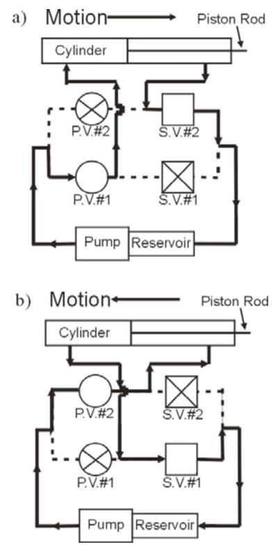
Schematic of hydraulic system in (a) forward direction and (b) reverse direction. Arrows depict direction of flow. P.V. = proportional valve, S.V. = solenoid valve. © 2008 IEEE.
When proportional valve #1 is activated and the piston is moving forward, solenoid valve #2 is in the open position to passively filter fluid from the cylinder’s port back to the reservoir, while solenoid valve #1 is closed (Fig. 2(a)). Conversely, when proportional valve #2 is activated and the piston is retracting, solenoid valve #1 is in the open position while solenoid valve #2 is closed (Fig. 2(b)).
The hydraulic cylinder (Bimba All-Stainless Non- Repairable Original Line, SS-0412-DXPW) is made of stainless steel to ensure MRI-compatibility. However, MRI-compatibility does not ensure absence of artifacts in the image. The entire system has been designed so that the RF needle tip and tissue clamp are within the scan field of the RF coil, while the other components, such as the cylinder and the force sensor, are outside the imaging area, but magnetically neutral. The cylinder operates at a maximum pressure of 250 psi (1723.5kPa), and has a 12 in (0.305m) stroke. The hydraulic power unit consists of a 2-gallon (0.00757cu.meters) reservoir, pump, and AC motor (Monarch Hydraulics Model No. M-404-0143). It operates in a pressure range of 50–2500 psi (344.7 kPa-17235 kPa).
2.1.3. Sensing and Control Components
The device is equipped with a linear encoder acting as a position sensor for the needle traversal. The encoder head (US Digital Part No. EMI-0-500, 500 LPI (197 LPcm)) is mounted to the top of the middle support of the device (Fig. 3), while the linear strip (US Digital Part No. LIN-500-12, 500 LPI (197 LPcm)) is mobile. The linear strip is clamped between two polypropylene sheets that are bolted to the slider, so the linear strip moves along with the slider, force sensor and RFA probe, while the encoder head is stationary. It is essential to keep the encoder head stationary to control the induced current as the electronics move through the magnetic field, as well as to minimize the possibility that the noise generated by the encoder and the cabling might interfere with the image during MRI scanning.
Fig. 3.
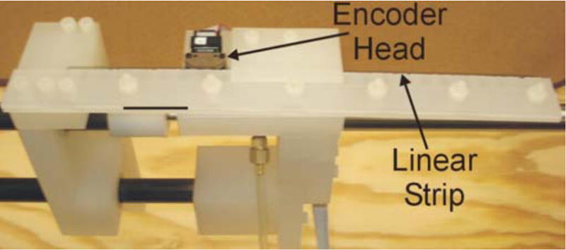
Close-up of encoder set-up.
In addition, a PL5 differential line drive is utilized to increase the signal output due to the long connecting wire running out of the scanning room. The force sensor (JR3 Model No. 20E12A-I25) is mounted to the force sensor plate on the slider. The RFA tool is then mounted directly onto the force sensor, such that the sensor records the forces/torques that are experienced by the RFA probe, in Fx, Fy, Fz, τx, τy, and τz, with a resolution of 0.002 N in Fx, Fy, and Fz and 0.00025 Nm in τx, τy, and τz. The force sensor has been custom-modified for MRI compatibility by JR3, Inc., with brass screws and hardwired cable (without an external connector). The RFA probe is mounted to a plate directly on the force sensor surface. Like the tissue clamp, the force sensor can be attached at various heights for use with various RF coils.
A dSPACE DS1103 controller board is used to record the position and force data from the sensors in real time, at a time step of 1ms. A PI control law is implemented based on the encoder data to precisely control the speed and motion of the piston rod, slider, and RFA probe.
2.1.4. Haptic Implementation
During the initial phases of the feasibility study, motion of the RFA probe was directly computer-controlled at various trapezoidal velocity profiles to determine the device’s ability to precisely respond to position and velocity commands. After fully developing this system, the dSPACE controller code was interfaced with a PHANToM haptic device (SensAble Technologies, Version 1.5A), operated in the control room (Fig. 1(b)). With this system, probe position is directly controlled in real-time by the position and velocity of the PHANToM stylus motion, while data from the force sensor is relayed back to the stylus to generate only real-time haptic feedback. Since the primary force sensing takes place along the x-axis of the force sensor, we displayed the x-component of the force through the PHANToM. This is a reasonable simplification since the majority of force should only be felt along the axis of the RFA probe. Force data from the sensor and velocity readings from the PHANToM stylus were filtered online with a 5th order Butterworth low-pass filter to transmit smooth velocity commands to the controller and to display force feedback to the user. The cutoff frequency for the filter is 6 Hz. This range produced the proper smoothing of the high frequency data while producing a negligible shift in the force profile. This enabled the user to directly insert the RFA probe into a tissue sample from outside the scanning room, while at the same time feeling the forces exerted onto the force sensor by the probe. It should be noted that the force sensor is connected at the base of the RFA probe, and therefore records the forces due to both friction and cutting [33].
2.2. System Modeling and Controller Design
To fully understand the dynamic response of the hydraulic system and design a suitable PI controller, the device was modeled with the assistance of the Matlab System Identification Toolbox. A series of experiments were performed in which constant voltages were applied to the proportional valves in both the forward and reverse directions, and encoder data was recorded at a time step of 1ms to determine the velocity of the probe in response to each step input. Five experiments were performed for each direction, at 8V, 12V, 16V, 18V, and 20V. For each experiment the velocity output data was arranged into a column vector, y, of size n, where n is the number of data points. Another column vector, u, of size n was also created containing the constant input voltage. These input vs. output data sets were imported into the System Identification Toolbox in Matlab. We chose to model the system as an over-damped second-order process model, whereby the transfer function in the s-domain took the following form:
| (1) |
where K is the static gain, Tw is the natural period, Td is the time delay, and ζ is the damping coefficient, which is greater than 1. The toolbox then used the input/output relationship of the step response to generate a best-fit model, obtaining the values for the transfer function parameters. Models were re-iterated until at least a 75% fit was reached. The standard deviations for the parameters in each direction were obtained, and after verifying a narrow spread of data, the average value for each parameter was selected to create an average model.
After obtaining a suitable plant model for both forward and reverse motion of the hydraulic cylinder, each system was simulated in Simulink® as a hybrid block diagram in the s- and z-domains, with a discrete controller and analog plant, as seen in Fig. 4. A proportional gain and an integral gain for the controller were selected for both forward and reverse motion, based on simulated rise time and steady-state error after several iterations.
Fig. 4.

Block diagram of closed-loop system. © 2008 IEEE.
2.3. MRI-Compatibility
To determine MRI-compatibility of the device, we must demonstrate (a) MRI image quality during device operation, and (b) accuracy of force readings during device operation inside the MRI.
2.3.1. Image Quality
To determine the degree of MRI-compatibility of the device, we first determined whether or not the presence of the device in the MRI induced any artifacts in the imaging region. To do this, we placed the device in the scanner (Siemens Magnetom 1.5T) with the RFA probe inserted into a phantom breast tissue and scanned several images during a dynamic scan (Fig. 5). To quantify the induced disturbance to the images naturally occurring in the dynamic scan sequence, we obtained the signal-to-noise ratio (SNR) of the images, where SNR is defined as the ratio of the mean pixel value of the signal and the standard deviation of the pixel value of the background noise [34]. To obtain these values, a small region was selected from the imaging area of the phantom tissue as the signal region of interest (ROI), while a large region from the background was selected as the noise ROI. Note that a homogenous region was chosen as the signal ROI, rather than the clinical region, to get a true reading of the induced noise to the image without any disturbance from the inhomogeneities in the tumor or probe. The mean pixel value and standard deviation of the ROI’s were obtained using image processing techniques in Matlab, and from here the SNR was calculated. This procedure was repeated for three images of varying qualities to determine the potential range of SNR generated by the device.
Fig. 5.

Breast phantom images used for SNR calculation, at varying image qualities. © 2008 IEEE.
2.3.2. Force Sensor Accuracy
In addition to the noise studies, we also need to verify that the force sensor readings are not affected by the MRI. To determine the effect of MRI on force values, we obtained force profiles during probe insertion into a homogenous phantom tissue sample, both inside and outside the MRI. The force profiles were then qualitatively compared.
2.4. Haptic Feedback Interface for Tumor Targeting and RFA
To demonstrate the ability of our system to perform the designated tasks of probe placement and tumor ablation, we must demonstrate (a) position control accuracy, (b) tumor targeting, and (c) RFA procedure and post-ablation force feedback.
2.4.1. Position Control Accuracy
We first needed to verify that the PHANToM device can accurately control the position of the RFA probe. To do this, we advanced and retracted the probe in the phantom tissue using the PHANToM stylus at approximately 5.08mm/sec, once again both inside and outside the MRI. We then compared encoder data for the position of the RFA probe with the position of the stylus at every time step, thus determining whether or not the device satisfactorily follows the stylus motion. In addition, we also verified that the correlation is the same both inside and outside the magnetic field.
2.4.2. Tumor Targeting Capability
Another necessary experiment was to demonstrate the PHANToM’s ability to guide the RFA probe into a tumor, while continuously imaging the needle and tumor region. At the same time, we also wanted to demonstrate the PHANToM’s ability to detect the tumor through force feedback of the needle-tumor interaction. To demonstrate this, we used a breast biopsy phantom tissue model with various inclusions that could be perceived within the MRI image. While advancing and retracting the RFA probe, we imaged the phantom tumor model region using a dynamic scan, which generated a sequence of MR scans taken at a chosen frame rate (3.7 seconds), allowing us to track the motion of the needle in real time. The MRI images were used to verify that the probe was inserted into the phantom tumor, while the force profile along the axis of the RFA probe was generated to analyze the haptic feedback due to the probe’s contact with the tumor. We then used the frame rate of the dynamic scan to determine the time at which each image was taken. This allowed us to compare the force profile to events in the images, such as needle insertion into the tumor. From here, we determined the system’s ability to detect the presence of a tumor via force feedback. Due to space constraints with the tissue clamp and breast phantom tissue model, the head RF coil was used for imaging in this experiment. While the breast coil would realistically be used in clinical practice, the choice of RF coil is immaterial for the purposes of this preliminary experiment.
2.4.3. Radiofrequency Ablation
An experiment was conducted to demonstrate the device’s ability to insert the RFA probe into an animal tissue model, perform RFA, and retract the needle post-ablation. A breast coil was used for imaging, with chicken breast as the animal tissue model (Fig. 1(a)). The PHANToM was used to guide the RFA probe into the chicken breast sample within the MRI until the tip of the needle was in the middle of the tissue. RFA was performed until an average temperature of 75°C was reached within the tissue, as determined by the RF needle. After RFA, to explore if there are differences in force feedback in ablated tissue vs. healthy tissue and if this difference can be detected by the surgeon, the RFA probe was inserted through the ablated tissue and it traversed into normal tissue and then retracted back through the ablated region. The animal tissue was then inspected to determine the diameter of the ablated region, which allowed us to correlate the force vs. displacement profile with the RFA probe’s entry and exit within normal and ablated tissue. While this re-entry through the ablated tissue would not actually occur in a clinical setting, it allowed us to examine important differences in force feedback between normal tissue and tissue that has been successfully ablated.
3. Results
3.1. System Modeling and Controller Design
Five step-response experiments were conducted for both forward and reverse motion of the hydraulic cylinder to study the input voltage vs. output velocity relationship for the plant. Subsequently, five second-order process models were developed from the System Identification Toolbox, generating best-fit values for the damping coefficient, static gain, time delay, and natural period. Fig. 6 shows the distribution of values for the damping coefficients in forward and reverse directions. Table 1 summarizes the averaged parameters for each direction, along with the associated standard deviations. We see that the standard deviations are low enough to allow for averaged parameters to be used to develop an overall open-loop transfer function for the plant, using Eq. 1 from Section 2.2. These models were simulated in Simulink® to obtain proportional and integral gains for the PI controller. Step response simulations were run until we achieved a steady state error of 0.1% and a rise time of 0.1 seconds. Based on these criteria, an integral gain of 300 was selected for both models, and proportional gains of 250 and 300 were selected for the forward and reverse directions, respectively.
Fig. 6.
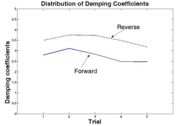
Distribution of damping coefficients
Table 1.
Average parameters for Second Order Process Model. © 2008 IEEE.
| Forward | Reverse | |||
|---|---|---|---|---|
| Avg. | St. Dev. | Avg. | St. Dev. | |
| Damp. Coeff. | 2.738 | 0.268 | 3.527 | 0.233 |
| Static Gain | 0.033 | 0.004 | 0.028 | 0.002 |
| Natural Period | 0.180 | 0.019 | 0.204 | 0.073 |
| Time Delay | 0.000 | 0.000 | 0.000 | 0.000 |
3.2. MRI-Compatibility
3.2.1. Image Quality
After obtaining various images with the system inside the scanner bore, no major artifacts were observed, and noise in the image was negligible (Fig. 5). We obtained a wide range of signal-to-noise ratios for the three tested images: 5.2 for Fig. 5(a), 21.0 for Fig. 5(b) and 106.7 for Fig. 5(c). Even the image with the worst quality (Fig. 5(a)) had an SNR of greater than 5. However, although the RFA probe is the standard MRI-compatible probe that is used in clinical practice, we observe a small artifact at the tip (Fig. 5).
3.2.2. Demonstration of Force Sensor Accuracy
We generated Force vs. Displacement profiles to compare the force sensor readings both inside and outside the MRI. Figure 7 shows the Force vs. Displacement profile along the long axis of the RFA probe (the x-axis).
Fig. 7.

Force profiles during needle insertion. a) Force in the X-direction vs. Displacement, b) Force in the Y-direction vs. Time, c) Force in the Z-direction vs. Time. © 2008 IEEE.
3.3. Haptic Feedback Interface for Tumor Targeting and RFA
3.3.1 Position Control Accuracy
Position profiles of the PHANToM stylus and the RFA probe are shown in Fig. 8. Fig. 8(a) depicts the position profile of the RFA probe outside the MRI, while Fig. 8(b) depicts the position profile inside the MRI. The maximum deviation of the observed position of the probe compared to the position of the stylus was calculated to be approximately 2.54mm.
Fig. 8.

Position profile for PHANTOM stylus and probe during probe insertion and withdrawal (a) outside the MRI and (b) inside the MRI. © 2008 IEEE.
3.3.2. Tumor Targeting Capability
A test was conducted to determine if the device could detect the presence of an inclusion within a phantom breast model (Fig. 9(a)). A dynamic scan (series of images taken quickly over several minutes at a set frame rate) was performed to track the path of the probe through the tissue and tumor (Fig. 9(c)–(f)). The captured images verify that the needle did in fact pass through the inclusion of interest. In addition, using the fact that the time between scans was 3.7 seconds, it is possible to determine the time at which the tip of the probe came in contact with the inclusion and the time at which it re-entered normal tissue. The time stamp of each image of interest is overlaid on the force profile obtained during the run (Fig. 9(b)).
Fig. 9.

(a) Photograph of breast phantom after tumor insertion. (b) Force profile during insertion and withdrawal into phantom breast tissue with tumor. Changing force profile coincides with images from the dynamic scan, depicting (c) initial position (t = 0.0s), (d) tissue puncture (t = 16.7s), (e) tumor puncture (t = 30.1s), and (f) withdrawal from tumor (t = 66.9s). © 2008 IEEE.
3.3.3. Radiofrequency Ablation
A final test was performed to study the device during and after RFA. After RFA, the RFA probe was inserted through the tissue sample, passing through the ablated region before entering normal tissue. Fig. 10 shows the force profile of the probe – tissue interaction during this reinsertion experiment, along with photographs of ablated region and the position of the probe as it enters and exits the ablated region.
Fig. 10.
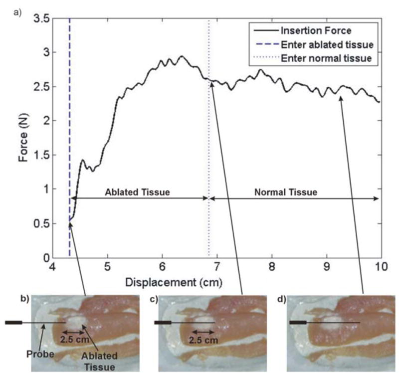
(a) Force vs. Displacement profile during needle insertion after RFA, through 2.5 cm region of ablated area and approximately 2.5 cm of normal tissue. Ablated tissue is shown depicting probe traversal as the probe tip (b) enters the ablated region, (c) exits the ablated region, and (d) travels through normal tissue.
4. Discussion
4.1 System Modeling and Controller Design
The system identification developed in Section 3.1 provides a simplified plant model for the dynamics of the device. This model was then used to design a preliminary PI controller to control the position and velocity of the RFA probe. From Fig. 8, we see that this design was successful in adequately controlling the motion of the RFA probe. Both inside and outside the MRI, the probe follows the position commands set by the PHANToM device, with negligible error. For the purposes of this initial experiment, this simplified plant model and PI controller are adequate.
However, in future design stages, a more complex plant model and controller must be designed. For a more exact model, it will be necessary to take into account the non-linearities that are inherent in a hydraulic system, requiring a more comprehensive nonlinear model that incorporates the actual dynamics of the hydraulic components in more detail. In addition, an impedance control strategy will be implemented, so that the motion of the RFA probe is affected by the contact forces between the patient and the probe, further enhancing the safety of the device. Finally, as teleoperation places the physician away from the patient (either in the same room or outside the imaging room), several watchdog controllers will be in place to ensure the patient safety.
4.2 MRI-Compatibility
4.2.1. Image Quality
From Fig. 5 and the SNR values discussed in Section 3.2.1, we see that the device introduces negligible noise to the MRI scanning environment. In other words, from an imaging point of view, the needle driver is MRI-compatible and does not introduce an artifact in the image, enabling its usage within the MRI environment during continuous imaging.
4.2.2. Force Sensor Accuracy
From Fig. 7a, we see a depiction of the correlation of the Force vs. Displacement profile during needle insertion inside and outside the MRI. We see a high force of around 1.5 N at about 1.25 cm of travel. This value corresponds to the large build-up of force that occurs before the probe punctures the surface of the homogenous phantom tissue sample [33, 35]. After this 1.5 N peak, we see that in both experiments the forces immediately drop below 0.5 N, before slowly increasing as the depth of insertion increases. The slow increase in force corresponds to the additional friction force that builds up as a higher surface area of the needle is in contact with the tissue, similar to our previous work on needle and soft-tissue interaction [33].
There has been prior work in the area of developing a MRI compatible sensors to be used for force feedback capability [36, 37]. Both of these projects are studying the validity of designing and utilizing fiber optic based sensors in the MR environment to achieve readings that are invariant to changing magnetic fields. In our work, the x-direction is not significantly affected by the magnetic field. Unfortunately, this was not the case for the forces in the y- and z-axes. Outside the MRI, Fy and Fz were negligible (Fig. 7b and 7c), which is what one would expect perpendicular to the direction of motion. However, inside the MRI scanner, the force sensor generated noticeable negative forces in the y-axis, and noticeable positive forces in the z-axis. Given that the magnetic field points in the x-direction of the force sensor (or the z-direction of the magnet bore in scanner coordinates), we hypothesize that the force offset is due to induced currents in the strain gages in the force sensor, resulting from the Lorentz magnetic forces acting on the particles in the strain gages. When a conductor moves through a magnetic field, the v⃗ x B⃗ component of the Lorentz forces causes the electrons to move through the conductor, i.e. resulting in a current through the strain gage wires. The amount of this induced EMF is dependent on three things: the velocity and direction of motion and the direction of the magnetic field. We can therefore quantify the induced currents as a function of the velocity and orientation of the force sensor. As shown in Figures 7b and 7c, where the velocity is constant, we observe a constant offset force (i.e. a constant offset in induced current), as predicted by the Lorentz equation. Future work will involve developing and verifying a model for the induced currents in the strain gage by identifying a relationship between the induced force and the force sensor’s orientation and velocity, leading to a method to calculate accurate force readings. Additionally, optical methods of force sensing will be explored as an alternative solution to the problem of force sensing within an MRI scanner. For the 1-DOF prototype, we chose to display the x-directional force to the haptic device, as that is a true representation of the force exerted on the force sensor by the probe.
4.3. Haptic Feedback Interface for Tumor Targeting and RFA
4.3.1. Position Control Accuracy
As seen from Fig. 8, the motion of the RFA probe attached to the 1-DOF needle driver coincides well with the movement of the PHANToM stylus, demonstrating the device can be controlled accurately with the haptic device. The maximum position error of 2.54 mm occurs at the time of change in direction of motion. During a relatively constant velocity, position error is minimized, implying that the error is due to a slight time delay in response to a rapidly changing velocity command, which is corrected in the steady state. Additionally, we see that position control is not significantly affected by the MRI.
4.3.2 Tumor Targeting Capability
Fig. 9 shows the force profile during insertion into the phantom tumor, overlaid with the time stamp of various images of interest during needle insertion. These times correspond to variations in force profile that can be explained by the time of puncture and increase in friction force while the needle is within the inclusion. For example, at about 16.7 seconds we see a peak in the force profile corresponding with the image scanned at 16.7 seconds (Fig. 9d). At about 30.1 seconds, we see a large variation in the force profile, which corresponds to Figure 9e, where the probe first begins to puncture the tumor. Finally, Fig. 9f depicts the instant that the probe is retracting and exiting the tumor, which results in a noticeable change in the force profile, as seen in Fig. 9b. Based on these observations, we concluded that the user can in fact detect the presence of an inclusion through both visual and haptic feedback. Furthermore, we determined that qualitative changes in the force profile that occur as the RFA probe interacts with a tumor during insertion. As seen in Fig. 9b, insertion into the tumor results in a higher frequency fluctuation in force, which is felt by the user through the PHANToM. Analyzing the force signal, we concluded that the frequency of force variation was approximately 0.5 Hz during insertion into the tumor (see Region A of Fig. 9b) and 1 Hz during withdrawal from the tumor (see Region B of Fig. 9b), well within the human perception range. This implied that the contact between needle and the tumor is perceptible by user the user through the PHANToM.
However, since the force sensor is mounted to the base of the needle, it is also important to note that the force readings include the force required to overcome friction between the needle and the tissue, not only the true cutting force. This has been extensively modeled and quantified [33, 35]. Therefore, the user experiences an increase in force as the needle moves through normal tissue, without any increase in cutting force or any contact with a tumor. From the data, we can conclude the following: contact with a tumor results in a fluctuation in force at the base of the needle, implying that the sum of the cutting force and the friction force fluctuates when the needle contacts a tumor. At this stage, we cannot conclusively determine whether the fluctuation results from an oscillating friction force or an oscillating cutting force, or a combination of both.
Additionally, we must consider that the actual forces experienced during multi-DOF interactions with a tumor are much more complex than the simple 1-DOF case in Fig. 9. In reality, needle bending, tissue deformation and tumor deflection have a significant effect on haptic feedback and the ability to accurately target a tumor. In these experiments, this was not an issue as the RFA probe: a) is relatively stiff (has an outside diameter of 2.16 mm) and b) enters perpendicular to the surface of the tissue and moves along the single DOF motion in the needle driver system. Also, the tumor was near the surface of the tissue, so needle flexure or bending did not result in positioning errors or large forces in the y- and z-directions. However, in the future it will be necessary to engineer a needle guide that keeps the needle stable as it enters the tissue. Future work will involve thorough studies of the mechanical properties of normal vs. cancerous breast tissue, along the expected haptic feedback during tumor puncture. A mechanical model of the RFA probe will also be developed to quantify needle bending, if any. Finally, the future design will incorporate a method of compressing and stabilizing the breast, thus minimizing the tumor deflection when contacted by the needle.
4.3.3. Radiofrequency Ablation
From Fig. 10(a), we see a large build-up of force as the probe traverses through the ablated region. High forces are expected here due to the increased toughness of the ablated tissue. As the probe enters normal tissue, there is a slight decrease in force. Even though the probe surface area in contact with the tissue increases as the displacement increases, we note that the total recorded force does not increase as the probe tip reaches normal tissue. Therefore, since we can assume that the probe cutting force is equal to the difference between the total force and the frictional force [33], we conclude that the probe cutting force is lower in normal tissue than in ablated tissue.
While these initial conclusions are apparent in the results shown in Fig. 10(a), more studies will be needed to draw further conclusions about the interactions between the probe and normal vs. ablated tissue. Meanwhile, it is demonstrated that the needle driver system successfully performed RFA on an animal tissue model while displaying force feedback variations in normal and ablated regions.
5. Conclusion
This paper discusses a design and set of experiments to explore the possibilities of creating a robot to perform teleoperated breast RFA procedures. The device presented here is a 1-DOF needle driver prototype that will be used and studied to help us better understand the issues related to teleoperated RFA, leading to a more complex multi-DOF robot that will be designed at a later stage in this project. The main issues that were explored in the paper were: (a) feasibility and accuracy of hydraulic actuation with long transmission lines, (b) MRI-compatibility, and (c) tumor detection via haptic feedback.
From the preceding discussion and results, we confirm our hypothesis that hydraulic actuation is an accurate method of controlling the RFA probe at low velocities. Additionally, we see that the needle driver is MRI-compatible with regards to image quality, position control, and force sensing along the long axis of the probe. However, the current generated by the magnetic field that induces a faulty force reading in the y- and z-axes remains a significant limitation of the design. This issue must be addressed before a more complex robot can be implemented, in which forces along the y- and z-axes will be critical to the success of the device. Solutions to the force-sensing problem will be explored in the next step of the design process, including a comprehensive model of the induced currents in the force sensor and compatibility tests of optical force sensors. Finally, we also conclude that the combination of haptic and visual feedback is a promising method of tumor detection for interventional procedures. Mechanical models of normal vs. cancerous tissue will be further explored to confirm our conclusions. Future work will also encompass the development of an impedance-based control scheme to minimize the RFA needle and tissue interaction forces.
It has been shown in the literature that MRI is a superior imaging modality for tumor boundary identification and temperature monitoring, but RFA under MRI is not currently widespread due to the space constraints within a closed-bore magnet as well as cost and time constraints due to the procedure. Also, the inaccuracy of tumor localization between a biopsy and the actual RFA procedure (since they are currently done on separate days) leads to registration errors and consequently inaccurate ablation boundaries. As a result, the goal of this research is to be able to perform biopsy and RFA in “one session” during continuous MRI guidance, with real-time haptic and visual feedback. We are currently working on developing a multiple degree-of-freedom MRI compatible robot. We have explored both hydraulic as well as pneumatic actuation techniques and have developed models for the entire robotic actuation system. The design of the robotic system is such that it will fit within the scanner, both standard and short bore, and is compact enough to carry out the biopsy as well as ablation procedure. The work presented in this paper is the first step towards the development of a robotic system with multiple degrees of freedom for RFA of breast tumors under continuous MRI imaging.
Acknowledgments
We acknowledge the support of National Science Foundation grant 0704138 and NIH grant 1R01EB008713 for part of this work.
Footnotes
Portions reprinted, with permission, from “Kokes, R.; Lister, K.; Gullapalli, R.; Bao Zhang; Richard, H.; Desai, J.P., Towards a needle driver robot for radiofrequency ablation of tumors under continuous MRI, ‘2008 IEEE International Conference on Robotics and Automation,’ Pasadena, California, 19-23 May 2008, pp. 2509-2514, Digital Object Identifier 10.1109/ROBOT.2008.4543590.” © 2008 IEEE
Publisher's Disclaimer: This is a PDF file of an unedited manuscript that has been accepted for publication. As a service to our customers we are providing this early version of the manuscript. The manuscript will undergo copyediting, typesetting, and review of the resulting proof before it is published in its final citable form. Please note that during the production process errors may be discovered which could affect the content, and all legal disclaimers that apply to the journal pertain.
References
- 1.Jemal A, Siegel R, Ward E, Hao Y, Xu J, Murray T, Thun M. Cancer Statistics, 2008. CA Cancer J Clin. 2008;58:71–96. doi: 10.3322/CA.2007.0010. [DOI] [PubMed] [Google Scholar]
- 2.Noguchi M, Earashi M, Fujii H, Yokoyama K, Harada K, Tsuneyama K. Radiofrequency ablation of small breast cancer followed by surgical resection. J Surg Oncol. 2006;93:120–128. doi: 10.1002/jso.20398. [DOI] [PubMed] [Google Scholar]
- 3.Singletary SE, Fornage BD, Sneige N, et al. Radiofrequency ablation of early-stage invasive breast tumors: an overview. Cancer J. 2002;8:177–180. doi: 10.1097/00130404-200203000-00011. [DOI] [PubMed] [Google Scholar]
- 4.Vlastos G. Minimally Invasive Approaches for Diagnosis and Treatment of Early-Stage Breast Cancer. The Oncologist. 2007;12:1–10. doi: 10.1634/theoncologist.12-1-1. [DOI] [PubMed] [Google Scholar]
- 5.Gazelle GS, Goldbery SN, Solbiati L, Livraghi T. Tumore Ablation with Radio-frequency Energy. Radiology. 2000;207:633–646. doi: 10.1148/radiology.217.3.r00dc26633. [DOI] [PubMed] [Google Scholar]
- 6.Ploeg Ivd, Esser Sv, Bosch Mvd, Mali W, Diest Pv, Rinkes I, Hillegersberg Rv. Radiofrequency Ablation for Breast Cancer: A Review of the Literature. Journal of Cancer Surgery. 2007;33:673–677. doi: 10.1016/j.ejso.2007.01.031. [DOI] [PubMed] [Google Scholar]
- 7.Izzo F, Thomas R, Delrio P, et al. Radiofrequency ablation in patients with primary breast carcinoma: a pilot study in 26 patients. Cancer. 2001;92:2036–2044. doi: 10.1002/1097-0142(20011015)92:8<2036::aid-cncr1542>3.0.co;2-w. [DOI] [PubMed] [Google Scholar]
- 8.Fornage BD, Sneige N, Ross MI, et al. Small (< or = 2-cm) breast cancer treated with US-guided radiofrequency ablation: feasibility study. Radiology. 2004;231:215–224. doi: 10.1148/radiol.2311030651. [DOI] [PubMed] [Google Scholar]
- 9.Singletary SE. Radiofrequency ablation of breast cancer. Am Surg. 2003;69:37–40. [PubMed] [Google Scholar]
- 10.Boctor E, deOliveira M, Choti M, Ghanem R, Taylor R, Hager G, Fichtinger G. Ultrasound Monitoring of Tissue Ablation via Deformation Model and Shape Priors. MICCAI. 2006;4191:405–412. doi: 10.1007/11866763_50. [DOI] [PubMed] [Google Scholar]
- 11.Daniels MJVT, Madsen EL, Zagzebski JA. P2H-5 Ultrasound-Based Temperature Imaging for Monitoring Electromagnetic Radiofrequency Ablation - Phantom Results. IEEE Ultrasonics Symposium; 2006. pp. 1766–1769. [Google Scholar]
- 12.Liu W, Zagzebski JA, Varghese T, Dyer CR, Techavipoo U. Automated thermal coagulation segmentation of three-dimensional elastographic imaging using an active contour model. IEEE Ultrasonics Symposium; 2004. pp. 36–39. [Google Scholar]
- 13.McGahan JP, Griffey SM, Schneider PD, et al. Radio-frequency electrocautery ablation of mammary tissue in swine. Radiology. 2000;217:471–476. doi: 10.1148/radiology.217.2.r00nv37471. [DOI] [PubMed] [Google Scholar]
- 14.Huppert PE, Trubenbach J, Schick F, Pereira P, Konig C, Clausen CD. MRI-guided percutaneous radiofrequency ablation of hepatic neoplasms: first technical and clinical experiences. Rofo. 2000;172:692–700. doi: 10.1055/s-2000-12045. [DOI] [PubMed] [Google Scholar]
- 15.Kacher DF, Jolesz FA. MR imaging-guided breast ablative therapy. Radiol Clin North Am. 2004;42:947–962. doi: 10.1016/j.rcl.2004.05.003. [DOI] [PubMed] [Google Scholar]
- 16.Lehman CD, Gatsonis C, Kuhl CK, Hendrick RE, Pisano ED, Hanna L, Peacock S, Smazal SF, Maki DD, Julian TB, DePeri ER, Bluemke DA, Schnall MD. MRI Evaluation of the Contralateral Breast in Women with Recently Diagnosed Breast Cancer. The New England Journal of Medicine. 2007;356:1295–1303. doi: 10.1056/NEJMoa065447. [DOI] [PubMed] [Google Scholar]
- 17.Gullapalli R, Zhang B, Richard H. MR Thermography for Radiofrequency Ablation. Journal of Interventional Radiology. 2007;18:PS-140. [Google Scholar]
- 18.Vigen KK, Jarrard J, Rieke V, et al. In vivo porcine liver radiofrequency ablation with simultaneous MR temperature imaging. J Magn Reson Imaging. 2006;23:578–584. doi: 10.1002/jmri.20528. [DOI] [PubMed] [Google Scholar]
- 19.Mcdannold N. Quantitative MRI-based temperature mapping based on the proton resonant frequency shift: Review of validation studies. International Journal of Hyperthermia. 2005;21:533–546. doi: 10.1080/02656730500096073. [DOI] [PubMed] [Google Scholar]
- 20.Zhang Y, Kambhamettu C. Integrated 3D scene flow and structure recovery from multiview image sequences. IEEE Comp Soc Conf Computer Vision and Pattern Recognition. 2000:674–681. [Google Scholar]
- 21.Eftychios C, Erbil A, Alpay O, Menelaos K, TNV Performance of interventions with manipulator-driven real-time MR guidance: implementation and initial in vitro tests. Magnetic Resonance Imaging. 2007;25:69–77. doi: 10.1016/j.mri.2006.08.016. [DOI] [PubMed] [Google Scholar]
- 22.Tsekos NV. Development of a robotic device for MRI-Guided Interventions in the Breast. IEEE 2nd Int. Symp. on Bioinformatics and Bioengineering; 2001. pp. 201–208. [Google Scholar]
- 23.Lewin JS, Nour SG, Connell CF, et al. Phase II clincal trial of interactive MR imaging guided interstitial radiofrequency thermal ablation of primary kidney tumors: initial experience. Radiology. 2004;232:835–845. doi: 10.1148/radiol.2323021351. [DOI] [PubMed] [Google Scholar]
- 24.Kaiser WA, Fischer H, Vagner J, Selig M. Robotic System for Biopsy and Therapy of Breast Lesions in a High-Field Whole-Body Magnetic Resonance Tomography Unit. Investigative Radiology. 2000;35:513–519. doi: 10.1097/00004424-200008000-00008. [DOI] [PubMed] [Google Scholar]
- 25.Krieger A, Susil R, Menard C, Coleman J, Fichtinger G, Atalar E, Whitcomb L. Design of a Novel MRI Compatible Manipulator for Image Guided Prostate Interventions. IEEE Trans Biomed Eng. 2005;52:306–313. doi: 10.1109/TBME.2004.840497. [DOI] [PMC free article] [PubMed] [Google Scholar]
- 26.Hata N, Hashimoto R, Tokuda J, Morikawa S. Needle Guiding Robot for MR-guided Microwave Thermotherapy of Liver Tumor using Motorized Remote-Center-of-Motion Constraint. IEEE International Conference on Robotics and Automation; 2005. pp. 1652–1656. [Google Scholar]
- 27.Larson B. Design of an MRI-compatible robotic stereotactic device for minimally invasive interventions in the breast. Transactions of the ASME. 2004;126:458–465. doi: 10.1115/1.1785803. [DOI] [PubMed] [Google Scholar]
- 28.Fischer G, DiMaio S, Iordachita I, Fichtinger G. Robotic Assistant for Transperineal Prostate Interventions in 3T Closed MRI. Int Conf Med Image Comput Assist Interv. 2007;10:425–433. doi: 10.1007/978-3-540-75757-3_52. [DOI] [PubMed] [Google Scholar]
- 29.Christoforou EG, Tsekos NV. Robotic manipulators with remotely-actuated joints: implementation using drive-shafts and u-joints. IEEE International Conference on Robotics and Automation; 2006. pp. 2866–2871. [Google Scholar]
- 30.Pillarisetti A, Pekarev M, Brooks AD, Desai JP. Evaluating the Effect of Force Feedback in Cell Injection. IEEE Transactions on Automation Science and Engineering. 2007 July;4:322–331. [Google Scholar]
- 31.Tholey G, Desai JP, Castellanos AE. Force Feedback plays a sgnificant role in Minimally Invasive Surgery - Results and Analysis. Annals of Surgery. 2005 January;241:102. doi: 10.1097/01.sla.0000149301.60553.1e. 2004. [DOI] [PMC free article] [PubMed] [Google Scholar]
- 32.Dempsey M, Condon B. Thermal Injuries Associated with MRI. Clinical Radiology. 2001;56:457–465. doi: 10.1053/crad.2000.0688. [DOI] [PubMed] [Google Scholar]
- 33.Hing JT, Brooks AD, Desai JP. A Biplanar Fluoroscopic Approach for the Measurement, Modeling, and Simulation of Needle and Soft tissue Interaction. Medical Image Analysis. 2007;11:62–78. doi: 10.1016/j.media.2006.09.005. [DOI] [PubMed] [Google Scholar]
- 34.Constantindes C, Atalai E, McVeigh E. Signal-to-noise Measurements in Magnitude Images from NMR Phasedarrays. Anual Int Conf of the IEEE; 1997. pp. 456–549. [DOI] [PMC free article] [PubMed] [Google Scholar]
- 35.Okamura AM, Simone C, O’Leary MD. Force Modeling for Needle Insertion into Soft Tissue. IEEE Transactions on Biomedical Engineering. 2004;50:1707–1716. doi: 10.1109/TBME.2004.831542. [DOI] [PubMed] [Google Scholar]
- 36.Chapuis DGR, Sache L, Burdet E, Bleuler H. Design of a simple MRI/fMRI compatible force/torque sensor. IEEE/RSJ International Conference on Intelligent Robots and Systems; 2004. pp. 2593–2599. [Google Scholar]
- 37.Moser R, Gassed R, Burdet E, Sachel L, Woodtli HR, Emi J, Maeder W, Bleuler H. An MR Compatible Robot Technology. IEEE International Conference on Robotics & Automation; 2003. pp. 670–675. [Google Scholar]