Abstract
Electrospinning was used to fabricate nonwoven nanofibrous tubular structures from Bombyx mori silk fibroin using an all aqueous process. The tubes were prepared for cell studies related to the bioengineering of small diameter vascular grafts. Prior to cell culture, the structures displayed a burst strength of 811±77.2 mmHg, sufficient to withstand arterial pressures. The tensile properties were similar to native vessels, with an ultimate tensile strength of 2.42± 0.48 MPa and a linear modulus of 2.45±0.47 MPa. Human endothelial cells and smooth muscle cells were successfully cultured on the electrospun silk, demonstrating the potential utility of these scaffolds for vascular grafts due to the combination of impressive mechanical properties and biological compatibility.
Keywords: silk, fibroin, vascular, endothelial, smooth muscle, blood vessels
Introduction
The prevalence of cardiovascular disease as the leading cause of death in the United States is driving the development of vascular replacements with long term patency.1 While synthetic polymeric materials have been successfully engineered for large diameter grafts (>6 mm), thrombosis has caused small diameter vessels to fail.2,3 Although autologous vessels, such as the saphenous vein, remain the standard for small diameter grafts, many patients lack suitable vessels for grafting due to vascular disease, amputation, or previous harvest. Therefore, tissue engineered vascular grafts have been explored to provide an alternative, with attempts to mimic the multi-layered structure and mechanical properties of native vascular tissue being a widely-accepted approach.4-7
Electrospinning is a promising technique explored in the development of biomaterial scaffolds for tissue engineering applications. This process generates porous structures with small-scale fiber diameters and high material surface area, which promote cell attachment and migration.8,9 Nanofibers are generated by applying high voltage to polymer solution. The charged solution forms a liquid jet that is drawn towards a grounded collection plate, during which time the solvent evaporates and fibers are formed. Typical diameters of the electrospun fibers are in the range of 50 nm to 1 micrometer. Previous studies have suggested that fiber diameter and morphology can be controlled by varying electrospinning parameters, ultimately affecting the scaffold mechanical properties and degradation rates.10-12
Despite a significant number of natural and synthetic materials that have been electrospun to form vascular graft scaffolds, challenges remain in terms of biocompatibility, mechanical properties, degradability and overall functional performance.12-16 Along these lines, we have been exploring a novel biological protein polymer: silk fibroin from the Bombyx mori silkworm. This material has proven applicable to a wide variety of biomaterials and tissue engineering needs, due to its unique combination of impressive mechanical properties, slow degradability and biocompatibility.17,18, 19 In addition, we have successfully developed a method to electrospin the silk through a completely aqueous process to generate useful new biomaterials.20 Other studies have assessed the mechanical properties of electrospun B. mori silk fibers and mats, and successfully demonstrated cell attachment to these materials.21-23 The electrospinning approach developed has further permitted the incorporation of labile cell signaling factors during the process with retention of biological function, as we have recently demonstrated in bone formation with incorporated bone morphogenetic protein-2 (BMP-2).8
In the present study, we have pursued the electrospinning of B. mori silk fibroin in the context of scaffold material for vascular grafting. Since silk fibroin has previously been studied for hematocompatibility,24 the combined utility of this novel protein in tubular structures to exploit the remarkable mechanical properties was considered an important next step in the pursuit of novel biomaterial applications for this class of fibroin protein. Electrospun silk tubes were generated and characterized for mechanical properties and for the support of human endothelial and smooth muscle cells.
Materials and Methods
Materials
Cocoons of B. mori silkworm silk were kindly supplied by M. Tsukada, Institute of Sericulture, Tsukuba, Japan. Silk fibroin aqueous solution was prepared as previous described.25 Briefly, cocoons were boiled for 20 min in an aqueous solution of 0.02 M Na2CO3, and then rinsed thoroughly with distilled water to extract the glue-like sericin proteins. The extracted fibroin was then dissolved in 9.3M LiBr solution at 60°C for 4 h, yielding a 20% (wt/v) aqueous solution. This solution was dialyzed against distilled water using Slide-a-Lyzer dialysis cassettes (MWCO 3,500, Pierce) at room temperature for 3 days to remove the salt. The dialysate was centrifuged 2 times, each at -5°C to 10°C for 20 min, to remove impurities and aggregates. The final concentration of the silk fibroin aqueous solution was approximately 8% (wt/v). All chemicals used in the processing were supplied by Sigma-Aldrich (St. Louis, MO). The silk solution was blended with poly(ethylene oxide) (PEO) to increase the solution viscosity and stabilize the jet during the electrospinning process, as we have previously reported.9 A 5.0 wt% PEO (900,000 g/mol) aqueous solution was blended with the aqueous silk fibroin solution to produce the 7.5 wt% silk/PEO solution for spinning.
Fabrication of Electrospun Tubular Scaffolds
Electrospun tubes were created using the multi-step process illustrated in Figure 1. A 15 cm long, 38 mm outer diameter 304 stainless steel tube (Small Parts Inc., Miami Lakes, FL) was installed on a mandrel, which was supported on both ends by sleeve bearings. The mandrel was linked via a pulley and timing belt configuration to a 24A Series permanent magnet DC motor (Bodine Electric Company, Chicago, IL). Through the use of a filtered Bodine PWM DC controller, variable speed was provided. In the initial processing step, silk yarn was wound on the stainless steel tube to facilitate subsequent removal of electrospun samples from the tube. The silk used for winding consisted of a yarn made from four white Brazilian raw B. mori silkworm fibers, listed as 20-22 denier by the importer, Rudolp-Desco Co. (Englewood Cliffs, NJ). In the electrospinning process, a silk/PEO solution was introduced to a 16 gauge needle, mounted to an electrode plate located at the top of an electrospinning chamber. A controlled solution flow rate of 0.013 mL/min was provided through the use of a syringe pump (Thermo Scientific, Model Sage-M362, Waltham, MA). The electrode plate was provided with approximately 10.5 kV using a 30 kV capacity high voltage power supply (Gamma High Voltage, Model ES30P-5W, Ormond Beach, FL). One of the bearings holding the mandrel was set to a potential of -10 V using a negative power supply (Welch AC/DC, 10 V DC max), ensuring the mandrel and mounted tube would serve as counter electrodes during rotation. Using a needle-to-mandrel spacing of 15 cm and a mandrel rotation rate of 3000 RPM, electrospinning was conducted until 2 mL of solution had been consumed.
Figure 1.
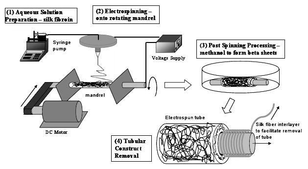
Summary of major processing steps for forming electrospun tubular scaffolds from silk fibroin.
After electrospinning, the stainless steel tube containing the electrospun sample was removed from the mandrel and placed in methanol (Chromasolv® gradient grade for HPLC ≥ 99.9%) for 10 minutes to induce a structural transition of the silk fibroin to the β-sheet to assure insolubility in water.20 The sample was then dried for 1 hour. The pre-wound silk was then removed by pulling the yarn carefully from beneath the electrospun sample. The gap created between the tube and sample allowed for easier removal of the electrospun sample. The final processing steps depended on the mechanical tests to be performed. For performing burst strength tests, barbed fittings were mounted to both ends of the samples, secured in place with silk yarn. Ring-shaped specimens used in radial tensile testing were created by slicing the tubular samples. All samples were soaked in water for at least 24 hours to leach out the PEO from the silk tubes prior to cell studies, as we have previously reported.9
Mechanical Testing Procedure - Tensile, Creep and Inflation Testing
Material characterization tests were performed to quantify the material stiffness and time dependent creep properties of electrospun silk tubular structures in hydrated conditions. For both, tensile and creep testing, cylindrical specimens with circular cross sectional area and with an axial length of 5 mm were prepared. Images of the rings were taken with an optical microscope (Axiovert S100, Zeiss, Germany) to determine wall thickness. To facilitate digital image capture and storage, a 3CCD color video camera (DXC-390, Sony, Tokyo, Japan), a frame grabber card (CG-7 RGB, Scion, Frederick, MD) and Scion-Image software version 1.9.1 were utilized. The images were analyzed using ImageJ from NIH. Microscope images were used to determine the wall thickness at circumferential intervals of 20 degrees.
The test procedure to determine tensile material properties of small diameter circular specimens was described by Bergund et al.26 Circular specimens were placed on spring mounts and subjected to cyclic loading. The initial length of the specimen over which the deformation was homogeneous is indicated by l0 and had a magnitude of 5.156 mm. Testing started with monotonic tensile elongation with a constant rate of 0.2 mm/s to determine the ultimate strength and strain at failure. A total of six new hydrated specimens were then subjected to loading and unloading cycles with subsequent elongation to failure at constant rate of 0.2 mm/s.
Similarly, to determine time dependent creep properties of electrospun tubular structures, six additional samples were subjected to three loading and unloading cycles to first precondition the material. The samples were subsequently stretched until 33% of the ultimate strength was reached. This value was maintained constant for 10 minutes to determine the deformation at constant load. Water droplets were added to the sample every two minutes to maintain the material in hydrated conditions. All creep specimens were from the same sample tube.
For burst analysis, five sample tubes were cut to 10 cm lengths, and polypropylene threaded barbed fittings were attached at each end. The tubular structures were mounted in an aluminum fixture to assist with sample installation and handling as well as to restrict changes in axial length during testing. The inflation tests were performed with samples submerged in water to maintain hydration and to simulate in vivo conditions. The internal pressure of the vessel was manually increased from 0 mmHg via the regulator at a near constant rate until rupture.
Cell Seeding and Culture on Scaffolds
Cell studies were carried out to assess the ability of the electrospun silk scaffolds to support the growth of human endothelial cells and smooth muscle cells, the primary cells of the vascular system. The human aortic endothelial cells (HAEC) (Clonetics, Walkersville, ML) of passage 5 and immortalized human coronary artery smooth muscle cells (HCASMC) of passage 13 (24 years old donor, female, no vascular disease) were used. Electrospun mats, 1×1 cm2 in size (∼ 0.2 mm thickness) were prepared from tubular scaffolds and sterilized by soaking in 70% ethanol for 20 min twice and following 3-time washes in PBS. Before seeding, the scaffolds were conditioned by incubation with Endothelial Growth Medium-2 (EGM-2, Cambrex Bio Science, Walkersville, ML) supplemented with 10% FBS and low glucose Dulbecco's Modified Eagle's Medium (DMEM, Invitrogen, Carlsbad, CA) with 10% FBS, penicillin/streptomycin and additional L-glutamine) for HAECs and HCASMCs, respectively, overnight at 37°C. The medium was aspirated and the cells were seeded onto the electrospun mats, placed in 24-well tissue culture plates with the density of 2.5×10⁴ cells/cm2. The cell-mat constructs were transferred into 12-well tissue culture plates 24 h after cell seeding. The constructs were cultured with EGM-2 and DMEM for HAECs and HCASMCs, respectively, at 37°C in a humidified incubator supplemented with 5% CO2. One ml of medium was used for each construct and the medium was changed every 2∼3 days over seven days.
Post-Cell Culture Scaffold Evaluation
Field emission electron scanning microscopy (FESEM – JEOL, JSM-7401F, Peabody, MA) was employed to evaluate the morphology of cells grown on the electrospun mats. The cell-mat constructs were taken out of the tissue culture plates after 7 days of culture and washed with PBS three times. Subsequently, the samples were fixed with 10% formalin solution at 4°C overnight and dehydrated through exposure to a gradient of alcohol, followed by air-drying in a fume hood. Samples were coated with gold for FESEM analysis.
Results and Discussion
Electrospun Silk Tubes
Tubes were successfully electrospun following the procedure outlined in the Methods section (Figure 1). The effective cross sectional area (wall thickness times axial length) was determined by averaging these data. The average wall thickness of all specimens was found to be 0.15 mm. Figure 2 shows macroscopic and microscopic images of a cylindrical specimen, the microscopic image indicates uniform wall thickness. Swelling of fibers from hydration and porosity may overestimate the actual load carrying cross section. To account of this phenomenon, we denominate the measured area as effective cross sectional area. Figure 3 schematically shows the boundary and load conditions on ring-like specimens and representative load-elongation data during preconditioning.
Figure 2.

(left) photograph of tubular scaffold, diameter = 5 mm, (middle) image of electrospun fibers, (right) microscopic image of circular cross section and uniform wall thickness. The diameter of the cylindrical specimen is 5 mm, the average wall thickness 0.15 mm.
Figure 3.
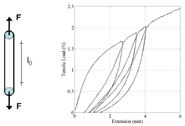
Loading conditions of small diameter ring like specimens and representative loading-unloading response during preconditioning.
Tensile Testing Results
Six cylindrical specimens with circular cross section were each subjected to three loading-unloading cycles followed by extension with constant rate up to failure. All specimens were obtained from the same sample tube, have a diameter and an axial length of 5 mm and an average wall thickness of 0.15 mm. A detailed view of the tensile load versus elongation during loading and unloading is shown in Figure 4. These results show that upon unloading, the specimen does not return to its original configuration indicating that some alignment in the fiber orientation occurs during preconditioning. Also, the data for unloading and reloading show that essentially no additional permanent deformation occurs during cyclic loading indicating that after preconditioning the response was elastic for deformations up to the maximum deformation achieved during preloading.
Figure 4.
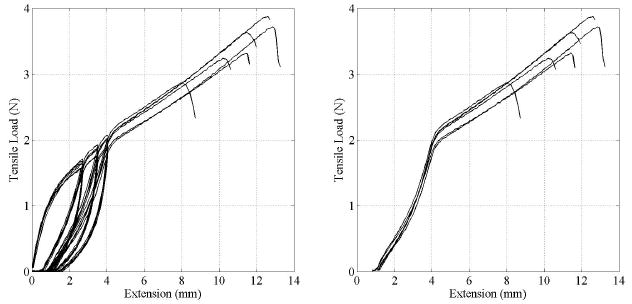
(left) Cyclic loading-unloading extension data of 6 ring-like specimens. (right) The same data after preconditioning.
The tensile test data of all six specimens tested were consistent as shown by the load versus elongation responses, including preconditioning (Figure 4). Some fiber alignment occured during cyclic loading, which resulted in a consistent and repeatable material response during final loading sequence up to failure. This is shown in the right graph in Figure 4. The load-extension data in Figure 4 were converted into stress-strain data using the cross sectional dimensions obtained from microscopic images. The extension data in Figure 4 shows the change in length of the initial gage length l0 = 5.156 mm and was used to determine the strain. This is given as the ratio of change in length (extension) over initial length. These stress-strain data were then used to calculate the elastic material properties after preconditioning. The elastic modulus was defined in the region from 25% to 75% of the yield stress, and was calculated as 2.45±0.47 MPa. The ultimate tensile strength was determined from the peak stress before failure and was 2.42±0.48 MPa. All relevant tensile test data of the six ring-like specimens tested are summarized in Table 1.
Table 1.
Summary of tensile test data of 6 ring-like specimens. The geometric dimensions were a diameter and axial length of 5 mm and an average wall thickness of 0.15 mm.
| Sample # | Yield Stress(MPa) | Yield Strain | UTS (MPa) | Max Load (N) | Linear Modulus (MPa) |
|---|---|---|---|---|---|
| 1 | 1.574 | 0.830 | 2.686 | 3.344 | 2.51 |
| 2 | 1.173 | 0.831 | 2.267 | 3.741 | 2.05 |
| 3 | 1.341 | 0.832 | 2.113 | 3.265 | 2.36 |
| 4 | 1.773 | 0.830 | 2.388 | 2.889 | 2.83 |
| 5 | 1.732 | 0.830 | 3.220 | 3.896 | 3.11 |
| 6 | 1.049 | 0.830 | 1.839 | 3.659 | 1.85 |
| Average | 1.440 | 0.830 | 2.419 | 3.466 | 2.449 |
These results are comparable to previously determined tensile properties of regenerated silk fibers. Formation of silk fibers from solution reduces tensile strength and stiffness when compared to native fibers.27,28 In addition, hydration of fibers reduces stiffness.27 Mechanical testing of electrospun silk mats produced by Ayutsede et al. demonstrated an initial modulus of 515 MPa and a tensile strength of 7.25 MPa.21 The electrospun silk tubes generated in the present study were hydrated during testing and the mats showed increased tensile strength and stiffness. In addition, the linear modulus of the tubes was significantly lower than the initial modulus of the mats due to the preconditioning cycles. The hydrated, preconditioned testing results compared favorably to native blood vessels (Table 2).
Table 2.
Summary of tensile properties of various vascular grafts – biomaterials utilized and native tissue.
| Material | Ultimate Tensile Strength (MPa) | Modulus (MPa) |
|---|---|---|
| Electrospun Silk Scaffold (this work) | 2.42±0.48 | 2.45±0.47 |
| Collagen, Fibrin (2 mg/mL)7 | 0.05 | 0.153 |
| Crosslinked Collagen, Fibroblasts26 | 0.37±0.08 | 2.82±0.42 |
| Thoracic Aorta,30 Carotid Artery31 | 1.95±0.60 | 0.04±0.9 |
| Electrospun Collagen32 | 1.5±0.2 | 52.3±5.2 |
| Electrospun Polylactic-co-glycolic Acid (10 wt %)31 | 6.0±0.2 | 71±7 |
Burst Strength
Burst strength ranged between 704 mmHg to 919 mmHg, with an average burst pressure of 811 mmHg (Figure 5). All tubes failed well above physiological pressures, indicating feasibility for these systems for in vivo study to meet mechanical loads. The rate at which pressure was increased during testing varied due to the manually controlled regulator. The dependency of the burst strength on pressure rate is depicted in the testing results. All samples exhibited the same failure pattern of an immediate decrease to approximately half of the burst pressure, a several second delay, and the final return to zero. This response was likely due to the multiple layers formed in the electrospun structure. The initial pressure drop is likely due to failure of the inner layers, after which the outer layers are subjected to the full internal pressure.
Figure 5.
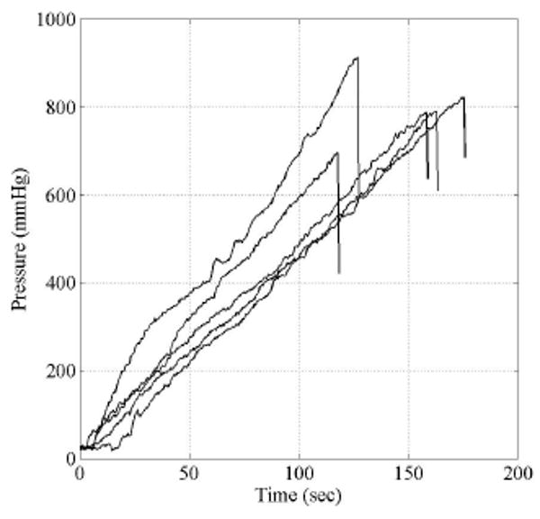
Internal pressure versus time of 5 sample tubes with an initial diameter of 5 mm. During inflation no axial extension was applied.
Creep Data
Figure 6 shows the time dependent responses of the tensile strain of ring-shaped electrospun specimens. A total of 6 cylindrical samples with a diameter and axial length of 5 mm where cut from the same tubular structure and mounted on an uniaxial testing machine following the procedures described by Bergund et al26 and shown schematically in Figure 1 of this paper. All samples were first subjected to three loading and unloading cycles for preconditioning. Subsequently, the axial load was increased monotonically up to a constant value of 1.457 N and the corresponding strain over the original reference length l0 determined. The time dependent change in strain with constant load was recorded (Figure 6). The results show that after 10 minutes the strain rate remains constant and did not increase to indicate any potential for material failure. The current experimental analysis does not provide conclusive evidence of the long term creep response. The long term time dependent material response, including fatigue and creep, is currently being investigated and will be part of a forthcoming manuscript.
Figure 6.
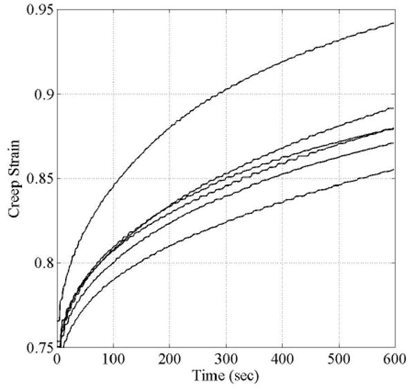
Time-dependent tensile strain of electropsun ring-like structures at a constant tensile load of 1.457 N. Test set-up for the time-dependent material response is similar to the tensile testing and shown in Figure 3.
Cell Responses on Silk Electrospun Scaffolds
Human aortic endothelial cells and coronary artery smooth muscle cells attached, spread and grew on the electrospun silk mats. A cell sheet and ECM formation on the mats is shown in Figure 7. The endothelial cells remained on the surface of the electrospun mats due to the small size pores in the nonwoven matrices (Figure 7B,C), while some of the smooth muscle cells migrated underneath the mats (Figure 7E,F). The ability to support cells of relevance to the vascular system suggests the electrospun silk tubes can be pursued in the context of further detailed study for vascular graft materials.
Figure 7.
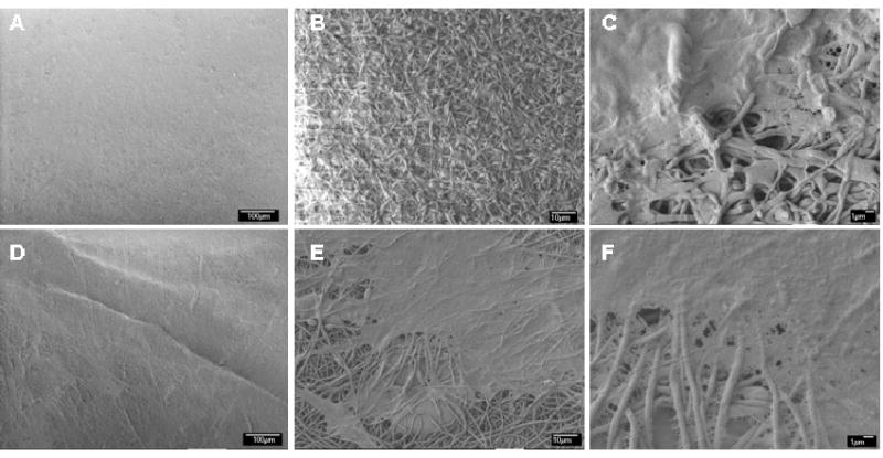
SEM images of human aortc endothelial cells (A-C) and human coronary smooth muscle cells (D-F) grown on electrospun silk mats after 7 days in culture at (A,D) 500, (B,E) 1000, and (E,F) 3,500 magnification. Scale bars are: A&D: 100 um; B&E: 10 μm; C&F: 1 μm)
Electrospun silk scaffolds have been previously studied as biomaterial substrates for cell growth related to tissue engineering,8,29 although the present work is the first report of the growth of vascular-related cell types of these scaffolds. Human bone marrow derived stromal cells (hMSCs) were successfully seeded and cultured on electrospun silk scaffolds and reached confluence after 14 days.29 Electrospun silk scaffolds were used as a delivery system for bone morphogenetic protein 2 (BMP-2) and nanoparticles of hydroxyapatite (nHAP) for in vitro bone formation from hMSCs.8 The electrospun silk scaffolds supported hMSC growth and differentiation toward osteogenic outcomes and the scaffolds with the co-processed BMP-2 supported higher calcium deposition and enhanced transcript levels of bone-specific markers.
Conclusions
Electrospun silk scaffolds were developed with sufficient structural integrity to allow handling and to maintain open conduits when hydrated. The scaffolds have promising mechanical characteristics for vascular grafts, including the ability to withstand arterial pressures and behave in a mechanically similar mode to native vessels. These systems also support vascular endothelial and smooth muscle cells, suggesting future potential for these protein systems in vessel applications. Scaffold properties may be further improved through fiber alignment and increased control of the electrospinning parameters.
Acknowledgments
This work was supported by NIH (EB002520 and EB003210) and the NSF (DMR). We thank Ms. Wendy Bauer, New England Medical Center, for providing the human smooth muscle cells and assistance in the cell culture. We also thank Ms. Samira Farboodmanesh, Nano-manufacturing Center, University of Massachusetts Lowell, for the help in FE-SEM imagining.
References
- 1.Thom T, Haase N, Rosamond W. Circulation. 2006;113:85. doi: 10.1161/CIRCULATIONAHA.105.171600. [DOI] [PubMed] [Google Scholar]
- 2.Nerem R, Seliktar D. Annual Review of Biomedical Engineering. 2001;3:225. doi: 10.1146/annurev.bioeng.3.1.225. [DOI] [PubMed] [Google Scholar]
- 3.Ratcliffe A. Matrix Biology. 2000;19:353. doi: 10.1016/s0945-053x(00)00080-9. [DOI] [PubMed] [Google Scholar]
- 4.L'Heureux N, Paquet S, Labbe R, Germain L, Auger F. The FASEB Journal. 1998;12:47. doi: 10.1096/fasebj.12.1.47. [DOI] [PubMed] [Google Scholar]
- 5.Niklason L, Gao J, Abbott W, Hirschi K, Houser S, Marini R, Langer R. Science. 1999;284:489. doi: 10.1126/science.284.5413.489. [DOI] [PubMed] [Google Scholar]
- 6.Hoerstrup S, Zund G, Sodian R, Schnell A, Grunenfelder J, Turina M. European Journal of Cardio-thoracic Surgery. 2001;20:164. doi: 10.1016/s1010-7940(01)00706-0. [DOI] [PubMed] [Google Scholar]
- 7.Cummings C, Gawlitta D, Nerem R, Stegemann J. Biomaterials. 2004;25:3699. doi: 10.1016/j.biomaterials.2003.10.073. [DOI] [PubMed] [Google Scholar]
- 8.Li C, Vepari C, Jin H, Kim H, Kaplan D. Biomaterials. 2006;27:3115. doi: 10.1016/j.biomaterials.2006.01.022. [DOI] [PubMed] [Google Scholar]
- 9.Kim H, Kim U, Vunjak-Novakovic G, Min B, Kaplan D. Biomaterials. 2005;26:4442. doi: 10.1016/j.biomaterials.2004.11.013. [DOI] [PubMed] [Google Scholar]
- 10.Zong X, Kim K, Fang D, Ran S, Hsiao B, Chu B. Polymer. 2002;43:4403. [Google Scholar]
- 11.Zong X, Ran S, Fang D, Hisao B, Chu B. Polymer. 2003;44:4959. [Google Scholar]
- 12.Stitzel J, Liu J, Lee S, Komura M, Berry J, Soker S, Lim G, Van Dyke M, Xzerw R, Yoo J, Atala A. Biomaterials. 2006;27:1088. doi: 10.1016/j.biomaterials.2005.07.048. [DOI] [PubMed] [Google Scholar]
- 13.Boland E, Matthews J, Pawlowski K. Frontiers in Bioscienc. 2004;9:1422. doi: 10.2741/1313. [DOI] [PubMed] [Google Scholar]
- 14.Inoguchi H, Kwon I, Inoue E, Kwon I, Inoue E, Takamizawa K, Maehara Y, Matsuda T. Biomaterials. 2006;27:1470. doi: 10.1016/j.biomaterials.2005.08.029. [DOI] [PubMed] [Google Scholar]
- 15.Matsuda T, Ihara M, Inogushi H, Kwon I, Takamizawa K, Satoru K. Journal of Biomedical Materials Research. 2005;73:125. doi: 10.1002/jbm.a.30260. [DOI] [PubMed] [Google Scholar]
- 16.Buttafoco L, Kolkman N, Engbers-Buijtenjuijs P, Poot A, Dijkstra P, Vermes I, Feijen J. Biomaterials. 2006;27:724. doi: 10.1016/j.biomaterials.2005.06.024. [DOI] [PubMed] [Google Scholar]
- 17.Altman G, Diaz G, Jakuba C, Calabro T, Horan R, Chen J, Lu H, Richmond J, Kaplan D. Biomaterials. 2003;24:401. doi: 10.1016/s0142-9612(02)00353-8. [DOI] [PubMed] [Google Scholar]
- 18.Horan R, Antle K, Collette A. Biomaterials. 2005;26:3385. doi: 10.1016/j.biomaterials.2004.09.020. [DOI] [PubMed] [Google Scholar]
- 19.Wang M, Jin H, Kaplan L, Rutledge G. Macromolecules. 2004;37:6856. [Google Scholar]
- 20.Jin H, Fridrikh S, Rutledge G, Kaplan D. Biomacromolecules. 2002;3:1233. doi: 10.1021/bm025581u. [DOI] [PubMed] [Google Scholar]
- 21.Ayutsede J, Gandhi M, Sukigara S, Micklus M, Chen H, Ko F. Polymer. 2005;46:1625. [Google Scholar]
- 22.Min B, Lee G, Kim S, Nam Y, Lee T, Park W. Biomaterials. 2004;25:1289. doi: 10.1016/j.biomaterials.2003.08.045. [DOI] [PubMed] [Google Scholar]
- 23.Unger R, Peters K, Wolf M, Motta A, Migliaresi C, Kirkpatrick C. Biomaterials. 2004;25:5137. doi: 10.1016/j.biomaterials.2003.12.040. [DOI] [PubMed] [Google Scholar]
- 24.Santin M, Motta A, Freddi G, Cannas M. J Biomed Mater Res A. 1999;46:382. doi: 10.1002/(sici)1097-4636(19990905)46:3<382::aid-jbm11>3.0.co;2-r. [DOI] [PubMed] [Google Scholar]
- 25.Sofia S, McCarthy M, Gronowicz G, Kaplan D. J Biomed Mater Res. 2001;54:139. doi: 10.1002/1097-4636(200101)54:1<139::aid-jbm17>3.0.co;2-7. [DOI] [PubMed] [Google Scholar]
- 26.Berglund J, Nerem RM, Sambanis A. Viscoelastic Testing Methodologies for Tissue Engineered Blood Vessels. Journal of Biomechanical Engineering 2005. 127(7):1176–84. doi: 10.1115/1.2073487. [DOI] [PubMed] [Google Scholar]
- 27.Xie F, Zhang H, Shao H, Hu X. International Journal of Biological Macromolecules. 2006;38:284. doi: 10.1016/j.ijbiomac.2006.03.021. [DOI] [PubMed] [Google Scholar]
- 28.Marasano E, Corsini P, Arosio C, Boschi A, Mormino M, Freddi G. International Journal of Biological Macromolecules. 2005;37:179. doi: 10.1016/j.ijbiomac.2005.10.005. [DOI] [PubMed] [Google Scholar]
- 29.Jin H, Chen J, Karageorgiou V, Altaman G, Kaplan D. Biomaterials. 2004;25:1039. doi: 10.1016/s0142-9612(03)00609-4. [DOI] [PubMed] [Google Scholar]
- 30.Adham M, Gournier J, Favre J, De La Roche E, Ducerf C, Baulieux J, Barral X, Pouyet M. Journal of Surgical Research. 1996;64:32. doi: 10.1006/jsre.1996.0302. [DOI] [PubMed] [Google Scholar]
- 31.Roeder R, Wolfe J, Lianakis N, Hinson T, Geddes L, Obermiller J. Journal of Biomedical Materials Research. 1999;47:65. doi: 10.1002/(sici)1097-4636(199910)47:1<65::aid-jbm9>3.0.co;2-f. [DOI] [PubMed] [Google Scholar]
- 32.Matthews J, Wnek G, Simpson D, Bowlin G. Biomacromolecules. 2002;3:232. doi: 10.1021/bm015533u. [DOI] [PubMed] [Google Scholar]


