Abstract
A study is made of the competition between failure modes in ceramic-based bilayer structures joined to polymer-based substrates, in simulation of dental crown-like structures with a functional but weak “veneer” layer bonded onto a strong “core” layer. Cyclic contact fatigue tests are conducted in water on model flat systems consisting of glass plates joined to glass, sapphire, alumina or zirconia support layers glued onto polycarbonate bases. Critical numbers of cycles to take each crack mode to failure are plotted as a function of peak contact load on failure maps showing regions in which each fracture mode dominates. In low-cycle conditions, radial and outer cone cracks are competitive in specimens with alumina cores, and outer cone cracks prevail in specimens with zirconia cores; in high-cycle conditions, inner cone cracks prevail in all cases. The roles of other factors, e.g. substrate modulus, layer thickness, indenter radius and residual stresses from specimen preparation, are briefly considered.
Keywords: Multilayers, Fracture, Fatigue
1. Introduction
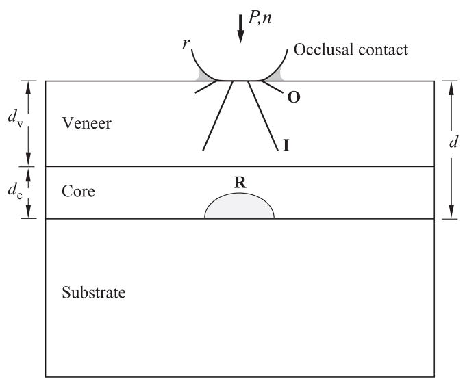
Considerable recent work has been done on the way brittle layer structures consisting of a weak and relatively compliant “veneer” joined to a strong and stiff “core” and glued to a polymeric base fail in contact loading with spheres [1–17]. Such configurations are representative of occlusal loading of all-ceramic veneer/core dental crowns fixed to tooth dentin [18–21]. They are also of general applicability to a broad range of engineering laminate structures where coating or glazing layers are used to provide functional (mechanical, thermal, aesthetic) protection for soft, compliant bulk substrates [6, 22–28]. Several fracture modes may operate under different conditions, but the most dominant are those indicated in Fig. 1: radial (R) cracking at the bottom surface of the core layer, where flexural tensile stresses concentrate; and outer (O) and inner (I) cone cracks at the top surface of the veneer layer, in the near-contact field. All of these cracks grow steadily with time in the presence of moisture due to the action of slow crack growth [29–31], but in the case of I cracks there is an additional “hydraulic pumping” effect from pressure-induced intrusion of water during cyclic loading [32,33]. Both radial and cone cracks can penetrate to the veneer/core interface in prolonged loading. At this point the structure is effectively compromised and so we designate it here as “failure”, although strictly it may remain intact and sustain further damage with prolonged loading.
Fig. 1.
Schematic showing competing outer (O) and inner (I) cone cracks in the veneer layer and radial cracks (R) in the core, with net layer thickness d = dv + dc, bonded to a compliant support base. The specimen is loaded with spheres of radius r at load P for number of cycles n in water (shaded).
The key question that we pose here is: which of the fracture modes in Fig. 1 dominates under any given set of conditions? Only by answering this question can we lay a sound foundation for optimizing all-ceramic layer systems for maximum resistance to failure. Several such influential conditions may be identified: crack evolution – the stability of fracture between initiation and failure; material properties (modulus, strength, toughness) – the role of core properties in determining the mechanics of fracture in both core and veneer; loading mode – single-cycle overload vs. prolonged cycling; geometrical variables – the role of layer thicknesses and cuspal curvature; residual stresses – the role of coefficient of thermal expansion (CTE) mismatch or other specimen preparation stresses.
This study seeks to address the key question of dominant fracture mode by conducting experiments on model flat trilayer systems [8,14,16]. Glass veneer plates are simply joined with an interlayer of epoxy resin to alumina or zirconia (Y-TZP) core plates. Glass has similar mechanical properties to dental porcelain, while alumina and zirconia are basic dental core ceramics. We chose epoxy adhesive as the preferred method of joining because it is cured at room temperature and therefore avoids CTE mismatch stresses [16]. It can also be applied in a sufficiently thin interlayer that the mechanics of the primary fracture modes are not significantly affected, and is sufficiently strong that delamination does not constitute a primary mode of failure. The ensuing all-ceramic bilayers are bonded to a compliant polycarbonate base, using the same epoxy adhesive, to simulate placement of a crown onto tooth dentin. The specimens are then loaded at their top surfaces with hard spheres in cyclic loading in a water environment, representing the occlusal function in the mouth. The evolution of fractures is observed in situ using video cameras [8,34]. The numbers of cycles needed to initiate radial cracks in the core and cone cracks in the veneer, and to propagate these cracks through the respective layers to the core/veneer interface, are measured. We demonstrate that both radial and cone crack modes can lead to failure, and that each can dominate in different material structures under different circumstances. Implications concerning the design of longer lifetime all-ceramic layer systems are discussed.
2. Materials and methods
The materials used to fabricate the trilayer structures depicted in Fig. 1 are indicated in Table 1 [16]. For the veneers, microscope soda-lime glass slides of thickness dv = 1.0 mm (Daigger, Wheeling, IL) were etched at their faces (10% HF, 30 s) to remove large flaws and polished at their edges for side viewing. For the cores, plates of polycrystalline alumina (AD995, CoorsTek, Golden, CO) and Y-TZP zirconia (Lava Frame, 3M ESPE, Morrow, GA) were diamond polished at their top and bottom faces to thickness dc = 0.5 mm. The combined net thickness d = 1.5 mm of the glass veneer and ceramic core layers is typical of dental crowns. A few polished monocrystalline sapphire plates (Goodfellow Ltd., Cambridge, England) and glass plates of thickness dc = 0.5 mm were also used as cores to facilitate in situ side viewing of radial cracks, the sapphire as a “transparent alumina” and the glass as a reference material.
Table 1.
Parameters for materials in this study
| Material | E (GPa) | S (MPa) | T (MPa m1/2) | N |
|---|---|---|---|---|
| Glass | 73 | 120 | 0.6 | 17.9 |
| Y-TZP | 210 | 1300 | 4.0 | 25 |
| Al2O3 | 372 | 465 | 3.0 | 26 |
| Polycarbonate | 2.35 |
In one set of specimens, the bottom surfaces of both the glass veneer and the core ceramic were pre-abraded (600 SiC grit) to introduce microcrack flaws, to ensure preferential radial cracking in the core in subsequent testing. Conversely, in another set of specimens, the top surfaces of the glass veneer and core ceramic were abraded to ensure cone cracking in the veneer. Abrasion of the surfaces immediately adjacent to the epoxy adhesive was included to test whether cracks in any one layer could penetrate into the other layer. The 1.0 mm glass plates were joined to the ceramic cores with epoxy resin (Harcos Chemicals, Bellesville, NJ) to form bilayers. After applying the adhesive, the plates were clamped and the epoxy allowed to cure for 2 days at room temperature, resulting in an adhesive interlayer <20 μm thick. The core bases of the resulting bilayers were then glued to polycarbonate slabs 12.5 mm thick (Hyzod, AlN Plastics, Norfolk, VA) with the same epoxy, which was allowed to cure under the same conditions.
The finished trilayers were loaded at their top surfaces with a WC indenter of radius r = 5.0 mm, an intermediate value within the occlusal function range [35]. The choice of WC was simply to enable repeated testing without the need to replace the indenter. (Comparable tests with glass indenters show virtually no shift in failure data [35].) A drop of water was placed at the indenter contact at the top surface and was constantly replenished during testing. Cyclic loading was conducted sinusoidally between a minimum load 2 N (to prevent the indenter wandering at the top surface) and maximum loads Pm up to 1300 N, at a frequency f = 10 Hz. The evolution of cone cracks in the glass veneer layers and of radial cracks in the glass or sapphire core layers was viewed in situ through the polished side walls with a video camera during testing. Radial cracking in the specimens with opaque polycrystalline alumina and zirconia cores could only be viewed in situ at the bottom surface, via a second video camera placed below the polycarbonate base. Immediately upon initiation of the radial cracks the specimens were viewed through the glass veneer from above, to determine whether fracture had penetrated the core.
Determinations of the material properties listed in Table 1 were made as follows. Moduli were obtained using a routine ultrasonic method (Grindosonic MK5, J.W. Lemmens Inc., St Louis, MO) [5]. Single-cycle strengths of each core material were measured from critical contact loads to induce bottom surface radial cracks in ceramic/polycarbonate bilayer specimens constructed as above with abraded ceramic undersurfaces but without the veneer, i.e. d = dc = 0.5 mm and dv = 0 [8]. Toughness values were determined from crack measurements at Vickers indentations [36]. Crack velocity exponents were obtained from existing cyclic fatigue data on these or similar ceramics [37].
3. Results
3.1. Crack morphology and failure
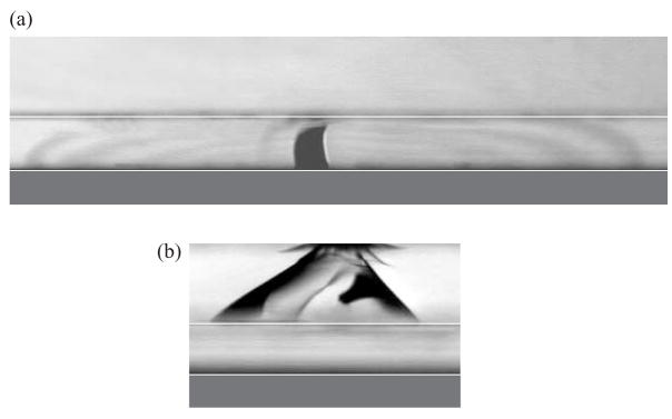
Fracture morphologies at failure, i.e. at the point where cracks intersect the veneer/core interface, are shown in Fig. 2. The examples are for specimens with glass veneers on transparent sapphire cores, from in situ side-view video clips. Fig. 2(a) is for etched glass veneer top surfaces and abraded sapphire core bottom surfaces, and for cyclic loading at Pm = 400 N. After a precursor stage of moisture-enhanced growth, radial cracks have initiated from a critical flaw at the sapphire bottom surface and abruptly propagated to the interface at nI = nF = 1014 cycles. At least two such cracks have formed in this instance, the visibility of which is determined by their orientation. One crack, observable as a faint, laterally extended interference fringe pattern, has a slightly off-normal inclination relative to the viewing axis. Another crack, seen as the dark shadow at the center, is closely parallel to the viewing axis. Note that while the radial cracks arrest at the veneer/core interface, they are still free to continue their lateral extension at higher loads, making them particularly dangerous. A characteristically unstable growth spurt to failure upon initiation (i.e. nF = nI) occurred in all specimens, including those with opaque alumina and zirconia cores, as verified by viewing through the top glass layer.
Fig. 2.
Failure crack morphologies in glass/sapphire/polycarbonate trilayers, from contact with WC spheres of radius r = 5.0 mm. (a) Core radial cracking in the bottom-surface abraded sapphire at Pm = 400 N and nF = 1014 cycles. For this crack mode, initiation and penetration occur simultaneously. (b) Veneer cone cracking in the top-surface abraded glass layer, showing dominant I cracks at Pm = 300 N and nF = 43613 cycles. For this mode, initiation generally occurs at a relatively low number of cycles, and the crack propagates stably prior to failure. Interfaces are accentuated by superimposed white lines, for clarification.
Fig. 2(b) shows the failure mode for abraded glass top surfaces and polished sapphire bottom surfaces, cyclic indentation at load Pm = 300 N. Under this loading condition an outer cone crack has initiated in the first cycle but has slowed down and remained relatively shallow through the test duration. An inner cone crack has initiated later, at nI = 420 cycles, and has grown steadily downward with continued cycling until final unstable penetration to the interface at nF = 43613 cycles.
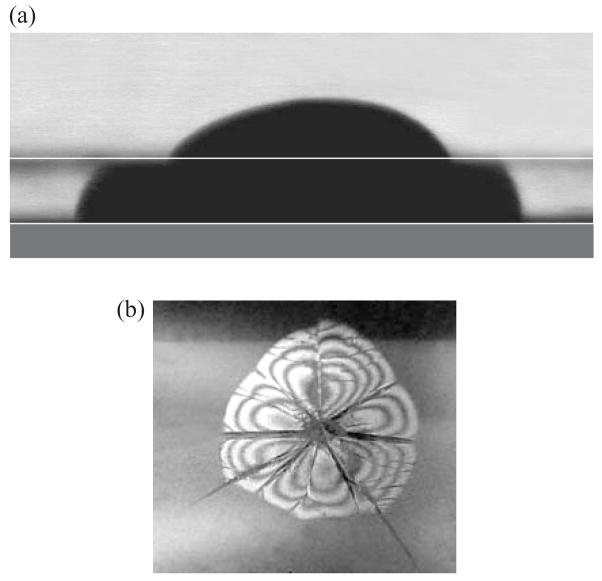
After intersecting the veneer/core interface, the arrested radial and cone cracks can evolve still further after continued cycling or increased loading. Radial cracks may nucleate subsidiary fracture modes. Two such subsidiary modes observed after extended cycling are shown in Fig. 3. In the first case, Fig. 3(a), for a specimen with both core and veneer undersurfaces abraded, the initially arrested radial crack has reinitiated within the upper glass layer on the other side of the soft epoxy barrier. In the second example, Fig. 3(b), delamination has occurred at the epoxy-bonded interface, seen here from below through the glass veneer layer as the bright fringe pattern. Note how the “petals” of the flower-like delamination pattern are confined by preceding radial cracks, indicating that delamination does not occur first. Arrested cone cracks also delaminate after extended cycling, into an annular configuration beyond the cone base [38]. By contrast, veneer cones never penetrate into the stiff, tough ceramic underlayer, even in specimens with abraded core top surfaces [15]. These subsidiary modes, while not in themselves responsible for primary failure, can nevertheless accelerate the catastrophic demise of crown-like layer structures.
Fig. 3.
Crack morphology in glass/sapphire/polycarbonate trilayers with bottom-surface abraded sapphire, showing subsidiary modes after failure by core radial cracking. (a) Reinitiation of the radial crack in an adjacent underabraded veneer layer. Indentation at Pm = 375 N, after n = 4129 cycles. (b) Delamination at the interface, indicated by a fringe pattern. Note how the delamination pattern is constrained by foregoing radials. Indentation at Pm = 375 N, after n = 3261 cycles.
3.2. Critical conditions for failure
Control tests were first run on ceramic/polycarbonate bilayer specimens to “calibrate” single-cycle strengths Sc for each core material. Values were computed from critical loads PB to initiate radial cracks in ceramic plates of thickness d = dc = 0.5 mm with abraded undersurfaces using the relation [8]
| (1) |
with Ec and Es moduli of core and substrate materials and B = 2.0. A minimum of five indentation tests were used to determine mean values of Sc for each material (Table 1).
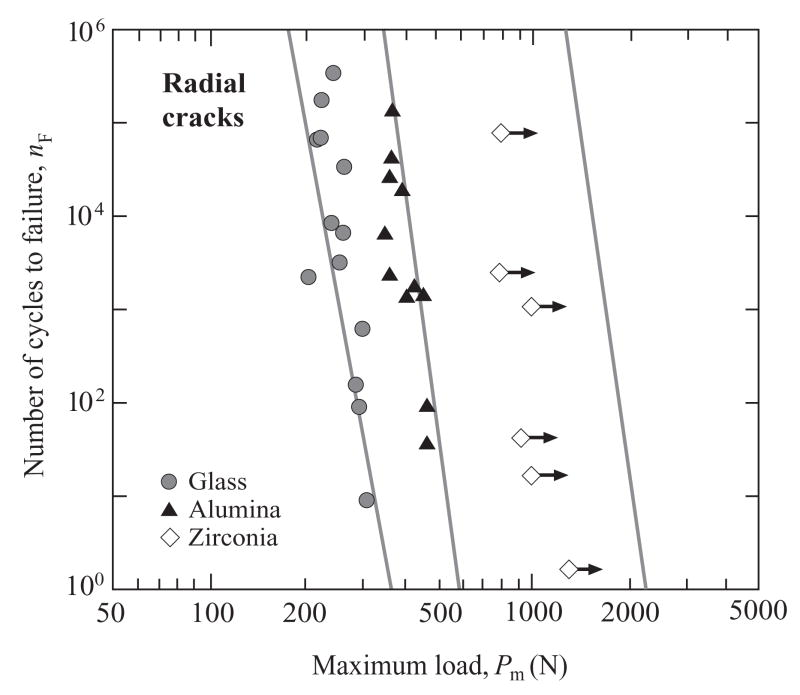
Fig. 4 plots nF vs. Pm for contact-induced core radial cracking in glass/ceramic/polycarbonate trilayers with glass, alumina and zirconia ceramic cores, for specimens with etched veneer top surfaces and abraded ceramic bottom surfaces. Recall that radial crack initiation and failure occur at the same number of cycles, i.e. nI = nF. Points are individual failures. The data show some scatter, indicative of material variations. The open symbol data for zirconia are from premature outer cone cracks from the etched top veneer surface, and are hence indicated as load runouts by arrows on the data points, signifying that real critical nF values are much higher. Solid lines are predictions from an explicit theoretical formulation based on initiation of radial cracks from surface flaws under the action of slow crack growth (Appendix A)
Fig. 4.
Number of cycles nF to contact-induced core failure from R radial cracks for epoxy-bonded glass/ceramic/polycarbonate trilayers, as a function of maximum contact load Pm, WC sphere r = 5.0 mm. Data are shown for glass, alumina and zirconia cores. Lines are predictions using Eqs. (2) and (3) in conjunction with data from Table 1.
| (2) |
where PR defines a single-cycle radial failure load
| (3) |
with E* = E*(Es/Ec,Ev/Ec,dv/dc) an effective modulus for the composite veneer/core bilayer and Ev modulus of veneer. These predictions were obtained by inserting d = 1.5 mm along with moduli (Ev, Ec, Es,), strengths (Sc) and crack velocity coefficients (N) from Table 1, and using an expression for E*(Es/Ec,Ev/Ec,dv/dc) in Appendix A. Although the predictions for zirconia are pre-empted by cone crack failures, the calculations account for the data shifts to longer lifetimes (or higher critical single-cycle loads) from glass to alumina to zirconia cores.
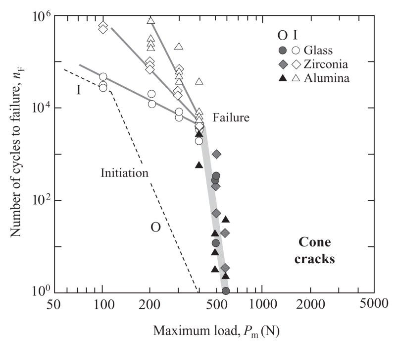
Fig. 5 is an analogous plot of nF vs. Pm for veneer cone cracking in the same glass/ceramic/polycarbonate trilayers, but for specimens with abraded top surfaces and polished core undersurfaces. Points are again individual specimen failures, with outer (O) and inner (I) cracks distinguished by filled and unfilled symbols. O cracks dominate in the high-load, low-cycle region and I cracks dominate in the low-load, high-cycle region. Note that the data for O cracks for different materials are indistinguishable within the scatter, while those for I cracks appear to diverge slightly at low Pm. Theoretical analysis is much less straightforward than for radial cracks, involving stable propagation through the veneer thickness within a combined Hertzian and flexural stress field (Appendix B). In the case of O cracks subject to slow crack growth, the relation for critical number of cycles to failure reduces to the same form as Eq. (2), i.e.
Fig. 5.
Number of cycles nF to contact-induced veneer failure from O and I cone cracks for epoxy-bonded glass/ceramic/polycarbonate trilayers, as a function of maximum contact load Pm, WC sphere r = 5. 0 mm. Failure data are shown for glass, alumina and zirconia cores. The lines through the O crack data are in accordance with Eq. (4), using N values from Table 1 and adjusting PO for each core material to give best fits. The lines through the I crack data are empirical fits to data. The dashed lines at the left are corresponding (material-independent) crack initiation functions (from [35]).
| (4) |
where PO is single-cycle load for O failure
| (5) |
with dv the veneer plate thickness, Tv the veneer toughness, F(Es/Ec,Ev/Ec,dv/dc) a function of relative elastic moduli and layer thicknesses, υ0 a crack velocity coefficient and γ a dimensionless constant. The function F(Es/Ec,Ev/Ec,dv/dc) has not been determined in explicit form, but is expected to be slowly varying. Accordingly, the broad solid line through the O crack data in Fig. 5 is drawn by taking an average N = 23 from Table 1 and adjusting PO to provide a best fit simultaneously for all materials. In the case of I cracks analysis is still more complex, involving as it does the superimposition of hydraulic pumping forces [32,33,39], so the lines through the data are purely empirical fits. It appears from this plot that stiffer cores do provide enhanced support against veneer failure, especially for I cracks. However, the data shifts are considerably less pronounced than for corresponding radial cracks in Fig. 4.
Finally in Fig. 5, dashed lines representative of the cone crack initiation function nI(Pm) for similar glass/ceramic/polycarbonate specimens under like indentation conditions are included for comparison with the nF(Pm) failure data [35]. Note that the nI(Pm) function is relatively insensitive to core material, depending as it does on near-contact conditions. Thus, for the spheres of radius r = 5.0 mm used here, initiation occurs well before failure, i.e. nI ≪ nF, emphasizing the “activated” nature of failure (as opposed to spontaneous failure at nI = nF in the case of radial cracks).
3.3. Design maps
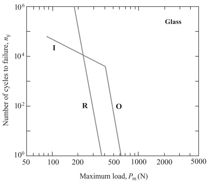
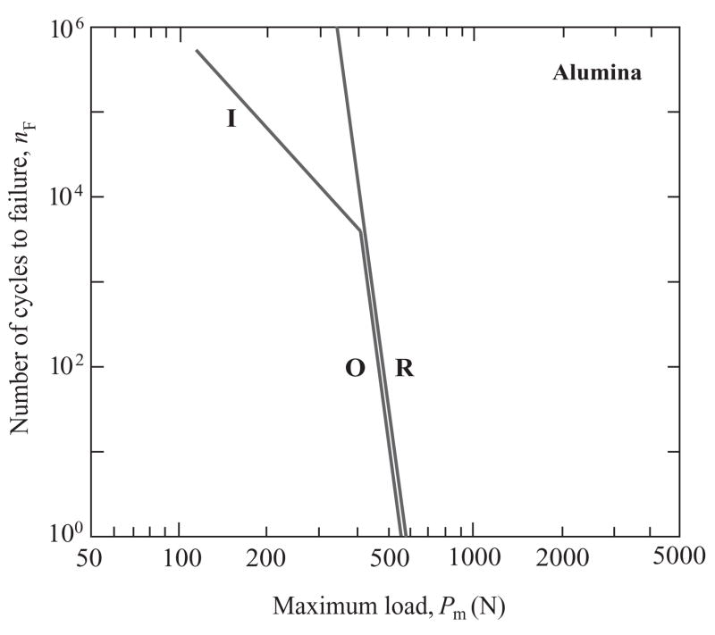
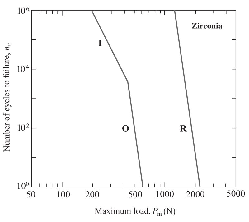
The results in Figs. 4 and 5 may be replotted on “design maps” for each core material comparing cone and radial cracking modes. This is done in Figs. 6, 7 and 8 for glass, alumina and zirconia cores respectively, using only solid line representations of the nF(Pm) data. We reiterate that these diagrams relate to specimens with net thickness d = 1.5 mm, and to surfaces with similar abrasion-flaw surface treatments. Shifts in the competition between the radial (R) and cone crack (O and I) modes with change in core ceramic are apparent. For glass cores, Fig. 6, R cracks fail before O and I cracks in the low-cycle, high-load region (even though, as evident from Fig. 5, O cracks may still initiate before R cracks). The situation reverses in the high-cycle, low-load region, where I cracks become highly dominant. For alumina cores, Fig. 7, R and O cracks appear equally likely to cause failure in the low-cycle region, but I cracks again dominate in the high-cycle region. For zirconia cores, failure invariably occurs from cones, O cracks in the low-cycle region and I cracks in the high-cycle region.
Fig. 6.
Number of cycles nF to contact-induced veneer failure from O and I cone cracks vs. core failure from R radial cracks, for glass/glass/polycarbonate trilayers, as a function of maximum contact load Pm. The lines are from Figs. 4 and 5, data omitted.
Fig. 7.
Number of cycles nF to contact-induced veneer failure from O and I cone cracks vs. core failure from R radial cracks, for glass/alumina/polycarbonate trilayers, as a function of maximum contact load Pm. The lines are from Figs. 4 and 5, data omitted.
Fig. 8.
Number of cycles nF to contact-induced veneer failure from O and I cone cracks vs. core failure from R radial cracks, for glass/zirconia/polycarbonate trilayers, as a function of maximum contact load Pm. The lines are from Figs. 4 and 5, data omitted.
4. Discussion
4.1. Design maps and fracture mechanics
We have demonstrated a strong competition between fracture modes in all-ceramic layer structures consisting of a weak outer veneer layer joined to a strong inner core ceramic layer. Under the contact loading conditions and layer thicknesses used in this study, the principal competitors are radial cracks (R) in the core and cone cracks (O and I) in the veneer (Fig. 1). Either of these modes can dominate in the high-load, low-cycle region, depending on the core material: R cracks in structures with weaker cores (glassy materials), at least in the low-cycle region (Fig. 6); O and I cracks in structures with stronger cores (zirconia), in all regions (Fig. 8). In all cases, inner cone cracks become dominant in the high-cycle, low-load region, i.e. under fatigue conditions. Formulations expressed in Eqs. (2)–(5) in the text (and in more detail in the Appendices) provide a sound, if approximate, basis for predicting how this balance between modes may shift with change in material or geometrical factors.
Further consideration of each fracture mode is in order. In the case of R cracks, Fig. 4, the mechanics are simplified by the fact that initiation and failure are simultaneous (i.e. nF = nI) in trilayer structures with stiff cores. This makes it unnecessary to have to deal with propagation through the complex stress field within the core layer. (This simplification does not extend to bilayer structures consisting of a single brittle layer on a soft substrate – as in monolithic crowns – where there is no internal interface to arrest the newly initiated radial crack [40].) The underlying fracture mechanics are governed by slow crack growth associated with intrusive moisture from the epoxy interlayer between core and base [41]. Thus the slopes of the nF(Pm) fatigue data in Fig. 4 are characteristically determined by the crack velocity exponent N in Eq. (2). The principal material property that appears in the critical load relation for single-cycle loading in Eq. (3) (i.e. Pm = PR at n = 1) is core strength Sc rather than toughness, typical of an initiation rather than propagation condition for failure [34]. This accounts for the strong rightward shift in the data in Fig. 4 in changing from glass to alumina to zirconia cores. This dependence on strength properties means that fatigue properties can be highly sensitive to flaw state, e.g. from preparatory sandblasting treatments used in crown finishing [42,43]. (Note the frequency dependence Sc ∝ f1/N in Eq. (A2), corresponding to PR ∝ f1/N in Eq. (3) and thus nF ∝ f in Eq. (2), consistent with a slow crack growth process governed by total time rather than number of cycles in the fatigue characteristic.) Core and substrate moduli are somewhat secondary factors in the formalism – critical loads in Eq. (3) decrease with higher Ec and lower Es [8].
As indicated in the preceding text, the mechanics of cone crack failure, Fig. 5, are less well developed, involving treatment of crack propagation through the veneer layer to the interface. The stress field is complex – for O cracks, a superposition of Hertzian and flexural components. The lifetime relation Eq. (4) for O cracks has exactly the same form as Eq. (2) for R cracks (and PO in Eq. (5) has the same frequency dependence as in Eq. (3), again indicative of a common slow crack growth mechanism with fatigue governed by total time rather than number of cycles). However, the material dependencies in the critical load relation Eq. (5) are quite different from those in Eq. (3). Now it is the veneer toughness Tv that controls, characteristic of failure by stable crack growth. In the case of engineering structures, this suggests that increasing the toughness of the veneer layer will increase resistance to surface cracking. However, with dental crowns the constraint of aesthetics restricts choice to low-toughness (and low-modulus) materials like porcelain with Tv ≈ 1 MPa m1/2 (Ev ≈ 70 GPa). Core material properties enter only through a modulus dependence in the slowly varying function F(Es/Ec,Ev/Ec,dv/dc) [16]. The dependence of veneer toughness and not strength in the fracture relations, for either failure (Eq. (5)) or initiation (Eq. (B2)), points to a much lower sensitivity of lifetime characteristics to surface flaw state [44]. In the case of I cracks, superposed hydraulic pumping forces complicate the fatigue process even further, with a strong mechanical as well as chemical component [33,45]. However, the experimental data do confirm that lifetimes for failure from I cracks do increase with core stiffness.
The plots in Figs. 4–8 enable a useful distinction to be made between single-cycle overload and cyclic fatigue failure, for the given layer thicknesses used in the present experiments. Single-cycle overload is equivalent to proceeding horizontally along the lower axis nF = 1 in these plots. In this case the competition is between R (with failure at Pm = PR) and O cracks (Pm = PO). Failure occurs from R cracks in bilayers with glass cores, from either R or O cracks with alumina cores, and from O cracks with zirconia cores. Fatigue failure is equivalent to proceeding vertically at Pm = constant. For low values of Pm, failure occurs invariably from I cracks, regardless of core material.
4.2. Additional variables
An additional material factor is substrate modulus. In our experiments we have used polycarbonate with a modulus Es = 2.35 GPa for experimental expediency (transparency). Dental crowns are usually seated onto tooth dentin, which has a modulus closer to Es = 16 GPa [7,46]. Such an increase in Es is equivalent to an increase in PR for core failure in Eq. (3) by a factor of about 2, with a corresponding shift in the nF(Pm) curves in Fig. 4 to the right. Physically, such a shift is attributable to a reduction in flexure in the overlying veneer/core structure [47]. The beneficial influence of reduced flexure is not expected to be quite so strong in the mechanics of veneer failure because of the slower variation of F(Es/Ec,Ev/Ec,dv/dc) in Eq. (5).
Variations in geometrical factors can also influence the lifetime characteristics. For radial cracks, the net thickness d is the controlling variable, with the characteristic flexural d2 dependence in PR in Eq. (3) [5,8]. Relative thickness is not an important factor within the range 0.25 < dv/dc < 0.75 (see Eq. (A4)) [8]. For cone cracks, the more relevant dimension is the thickness dv of the veneer, with dependence dv3/2 in Eq. (5). Scaling net thickness d while keeping relative thickness dv/dc fixed will substantially shift both radial and cone curves nF(Pm) in Figs. 6–8, so that, although the shifts will be a little stronger for R cracks, the balance will not be greatly affected. Note, however, that the critical load to initiate O cracks in Eq. (B2) is independent of d, so the nI(Pm) curves will undergo no such shift. If d is made sufficiently small (thin film region), nF for cones could actually diminish below nI, in which case cone failure would occur spontaneously at initiation. (In this region R cracks could become suppressed as the core undersurfaces become enveloped in the compressive zone beneath the contact [48].)
Another relevant geometrical variable is indenter radius, r (Fig. 1), which we may consider as equivalent to an occlusal contact radius in the context of dental crowns [35]. While not an issue in the failure relations for either radial cracks or cone cracks in Eqs. (3) and (5), r is the controlling geometrical variable in the expression for crack initiation in Eq. (B2). Increasing r increases nI in Eq. (B1), diminishing the gap between nI(Pm) and nF(Pm). For sufficiently large r the condition nI > nF may be met at any given Pm, corresponding to spontaneous cone crack failure and tilting the balance back toward radial crack failure [35].
The present study has focused on veneer/core structures bonded by epoxy resin, in an effort to avoid CTE mismatch stresses. Residual stresses could still arise from adhesive shrinkage, but we have kept these negligibly small by maintaining very thin interlayers (<20 μm). In the preparation of real dental crowns by fusion of porcelain veneers onto core layers, minimization of CTE stresses demands close matching of expansion coefficients. A CTE mismatch of less than 1×10⁻⁶ K−1 can mean stresses of the order of 50 MPa within the layers [16]. This is a factor that needs to be borne in mind when choosing layer materials for optimal biomechanical systems.
4.3. Other damage modes
Our focus in this work has been on just two failure modes, radial and cone cracking. For the brittle materials, layer thicknesses and contact conditions considered here, these modes are dominant. However, other potential failure modes can occur under different circumstances. We have already mentioned delamination at the veneer/core interface (Fig. 3(b)). To avoid delamination, it is necessary to ensure strong bonding. The epoxy used here is strong enough that delamination occurs only as a secondary mode. On the other hand, issues arise as to the longevity of polymer-based adhesives in vivo. Also, polymer-based adhesives are compliant, and if the interlayer is allowed to become too thick, enhanced flexure beneath the contact may initiate premature radial cracks at the bottom of the veneer instead of in the core [49]. Use of a stiffer adhesive (dental composite) might alleviate such flexure, but at the same time may transmit stresses across the interface, enhancing penetration or reinitiation modes (Fig. 3(a)). Use of less brittle veneering ceramics, such as glass–ceramics, can lead to premature initiation of extremely deleterious median cracks within a quasiplastic contact field [50,51]. Finally, our restriction to extended flat surfaces ignores the possibility of edge cracks, which may initiate at the support “margins” of curved specimens [52].
4. Summary
The occlusal-like loading of brittle crown-like veneer/core structures can trigger several competing fracture modes, all capable of causing failure by crack propagation to the intervening interface. Most of these modes will never be observed in conventional flexural strength or tensile tests on bar or disk specimens. Contact loading of model glass/ceramic/polycarbonate layer systems with spherical indenters offers a simple and powerful route to systematic investigation of such modes, particularly of dominant radial and cone fracture. Design maps can be constructed quantifying the lifetime characteristics of these and other failure modes for given material types and layer thicknesses. Fracture mechanics analysis provides a sound (if approximate) basis for determining the roles of key material and geometrical variables. Although we have used dental crowns as a case study, the results presented here are relevant to a broad range of engineering applications with brittle coatings and laminates.
Acknowledgments
This work was supported by a grant from the National Institute of Dental and Craniofacial Research (PO1 DE10976). Certain equipment, instruments or materials are identified in this paper in order to specify experimental details. Such identification does not imply recommendation by the National Institute of Standards and Technology.
Appendix A: Fracture mechanics for radial cracks in core
Consider a flaw of characteristic size cf ≪ d at the bottom core surface (Fig. 1) subject to cyclic loading at frequency f. Suppose that the crack growth is governed by a slow crack growth relation of form υ = υ0(K/Tc)N, where K is a stress-intensity factor, N is an exponent, υ0 is a coefficient and Tc is the core toughness. Integration over time and crack size yields a relation for the number of cycles to flaw instability [41,53]
| (A1) |
where σm is the peak tensile stress and Sc is core strength in single-cycle loading (n = 1)
| (A2) |
with ψ a crack geometry coefficient (near unity).
The peak stress at the bottom of the core ceramic layer can be evaluated by modifying Eq. (1) in the text to allow for the effect of an overlying veneer [8]
| (A3) |
where d = dv + dc (Fig. 1) and E* is an effective modulus for combined veneer and core
| (A4) |
with ε = Ev/Ec and δ= dv/dc.
Noting that nI = nF for radial cracks in the core, we can combine Eqs. (A1)–(A4) to obtain the critical number of cycles for radial failure
| (A5) |
with critical load for crack initiation in single-cycle loading
| (A6) |
Appendix B: Fracture mechanics for cone cracks in veneer
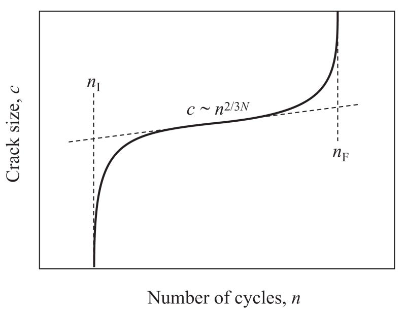
The fracture mechanics for O and I cone cracks within the veneer are more complex. This is particularly so for I cracks, where additional hydraulic pumping forces are superposed onto the crack velocity field [33]. For O cracks, the crack evolution c(n) takes the general form in Fig. B1. Three stages are identified: initiation (initial “pop-in” instability), propagation (steady state) and failure (intersection with the interface):
Fig. B1.
Schematic of cone crack evolution c(n) through veneer, showing the critical number of cycles nI needed to initiate cracks, to reach the steady state stage and to reach failure nF.
(i) Initiation
Crack pop-in occurs within the near-contact field, remote from the veneer/core interface. Hence the mechanics are essentially the same as for a monolith of the veneer material. Explicit relations for O cracks located at radial coordinate R on the veneer surface are given by [12]
| (B1) |
where PI is the critical load to initiate an O crack in single-cycle loading (n = 1)
| (B2) |
with Tv the veneer toughness and α = α (Ei/Ev) a dimensionless constant, with Ei indenter modulus [53]. Note the dependence on radius r but not on thickness d.
(ii) Propagation
The O crack now enters the contact far field but remains distant from the interface. Again, relations for monoliths provide a first approximation for the crack evolution function c(n) [53]
| (B3) |
where the back-extrapolated crack length intercept c1 at n = 1 is defined by [12]
| (B4) |
with β = β (N,Es/Ec,Ev/Ec,dv/dc) an unknown, dimensionless quantity and χ an indentation constant. Note that c(n) is now independent of both r and d.
(iii) Failure
The O crack senses the interface and becomes subject to dominant far-field flexure stresses. Again, this stress field is complex, but a relation for crack growth through a single brittle layer on a compliant base offers an approximate solution [13]:
| (B5) |
where PO is the critical load for failure in single-cycle loading
| (B6) |
with F(Es/Ec,Ev/Ec,dv/dc) a dimensionless function of relative moduli and γ a dimensionless constant. The governing dimension is now the veneer thickness dv.
Footnotes
Publisher's Disclaimer: This is a PDF file of an unedited manuscript that has been accepted for publication. As a service to our customers we are providing this early version of the manuscript. The manuscript will undergo copyediting, typesetting, and review of the resulting proof before it is published in its final citable form. Please note that during the production process errors may be discovered which could affect the content, and all legal disclaimers that apply to the journal pertain.
References
- 1.Diao DF, Kato K, Hokkirigawa K. Trans ASME J Tribol. 1994;116:860. [Google Scholar]
- 2.Lardner TJ, Ritter JE, Zhu G-Q. Journal of the American Ceramic Society. 1997;80:1851. [Google Scholar]
- 3.Wakabayashi N, Anusavice KJ. Journal of Dental Research. 2000;79:1398. doi: 10.1177/00220345000790060801. [DOI] [PubMed] [Google Scholar]
- 4.Miranda P, Pajares A, Guiberteau F, Cumbrera FL, Lawn BR. Journal of Materials Research. 2001;16:115. [Google Scholar]
- 5.Deng Y, Lawn BR, Lloyd IK. Journal of Biomedical Materials Research. 2002;63B:137. doi: 10.1002/jbm.10091. [DOI] [PubMed] [Google Scholar]
- 6.Lawn BR. Current Opinion in Solid State and Materials Science. 2002;6:229. [Google Scholar]
- 7.Lawn BR, Deng Y, Miranda P, Pajares A, Chai H, Kim DK. Journal of Materials Research. 2002;17:3019. [Google Scholar]
- 8.Deng Y, Miranda P, Pajares A, Guiberteau F, Lawn BR. Journal of Biomedical Materials Research. 2003;67A:828. doi: 10.1002/jbm.a.10161. [DOI] [PubMed] [Google Scholar]
- 9.Miranda P, Pajares A, Guiberteau F, Deng Y, Lawn BR. Acta Materialia. 2003;51:4347. [Google Scholar]
- 10.Miranda P, Pajares A, Guiberteau F, Deng Y, Zhao H, Lawn BR. Acta Materialia. 2003;51:4357. [Google Scholar]
- 11.Lawn BR, Pajares A, Zhang Y, Deng Y, Polack M, Lloyd IK, Rekow ED, Thompson VP. Biomaterials. 2004;25:2885. doi: 10.1016/j.biomaterials.2003.09.050. [DOI] [PubMed] [Google Scholar]
- 12.Zhang Y, Bhowmick S, Lawn BR. Journal of Materials Research. 2005;20:2021. [Google Scholar]
- 13.Bhowmick S, Zhang Y, Lawn BR. Journal of Materials Research. 2005;20:2792. [Google Scholar]
- 14.Hermann I, Bhowmick S, Zhang Y, Lawn BR. Journal of Materials Research. 2006;21:512. [Google Scholar]
- 15.Kim J-W, Bhowmick S, Hermann I, Lawn BR. Journal of Biomedical Materials Research. 2006;79B:58. doi: 10.1002/jbm.b.30511. [DOI] [PubMed] [Google Scholar]
- 16.Hermann I, Bhowmick S, Lawn BR. Journal of Biomedical Materials Research. in press. [Google Scholar]
- 17.Kim B, Zhang Y, Pines M, Thompson VP. Journal of Dental Research. doi: 10.1177/154405910708600207. submitted. [DOI] [PubMed] [Google Scholar]
- 18.McLean JW. The nature of dental ceramics and their clinical use. Vol. 1. Chicago, IL: Quintessence; 1979. The science and art of dental ceramics. [Google Scholar]
- 19.Kelly JR. Annual Reviews of Materials Science. 1997;27:443. [Google Scholar]
- 20.Kelly JR. Journal of Prosthetic Dentistry. 1999;81:652. doi: 10.1016/s0022-3913(99)70103-4. [DOI] [PubMed] [Google Scholar]
- 21.Lawn BR, Deng Y, Thompson VP. Journal of Prosthetic Dentistry. 2001;86:495. doi: 10.1067/mpr.2001.119581. [DOI] [PubMed] [Google Scholar]
- 22.Ball A. Journal de Physique IV. 1997;7:C3921. [Google Scholar]
- 23.Grant PV, Cantwell WJ, McKenzie H, Corkhill P. International Journal of Impact Engineering. 1998;21:737. [Google Scholar]
- 24.Grant PV, Cantwell WJ. Journal of Testing and Evaluation. 1999;27:177. [Google Scholar]
- 25.Bennison SJ, Jagota A, Smith CA. Journal of the American Ceramic Society. 1999;82:1761. [Google Scholar]
- 26.Maekawa I, Sudou H, Uda K. International Journal of Impact Engineering. 2000;24:673. [Google Scholar]
- 27.Padture NP, Gell M, Jordan EH. Science. 2002;296:280. doi: 10.1126/science.1068609. [DOI] [PubMed] [Google Scholar]
- 28.Bhowmick S, Jayaram V, Biswas SK. Acta Materialia. 2005;53:2459. [Google Scholar]
- 29.Wiederhorn SM. Journal of the American Ceramic Society. 1967;50:407. [Google Scholar]
- 30.Wiederhorn SM, Bolz LH. Journal of the American Ceramic Society. 1970;53:543. [Google Scholar]
- 31.Lawn BR. Fracture of brittle solids. Vol. 2. Cambridge: Cambridge University Press; 1993. [Google Scholar]
- 32.Zhang Y, Kwang J-K, Lawn BR. Journal of Biomedical Materials Research. 2005;73B:186. doi: 10.1002/jbm.b.30195. [DOI] [PubMed] [Google Scholar]
- 33.Chai H, Lawn BR. Scripta Materialia. 2006;55:343. [Google Scholar]
- 34.Chai H, Lawn BR, Wuttiphan S. Journal of Materials Research. 1999;14:3805. [Google Scholar]
- 35.Bhowmick S, Meléndez-Martínez JJ, Herman I, Zhang Y, Lawn BR. Journal of Biomedical Materials Research. in press. [Google Scholar]
- 36.Anstis GR, Chantikul P, Marshall DB, Lawn BR. Journal of the American Ceramic Society. 1981;64:533. [Google Scholar]
- 37.Zhang Y, Lawn BR. Journal of Biomedical Materials Research. 2004;69B:166. doi: 10.1002/jbm.b.30083. [DOI] [PubMed] [Google Scholar]
- 38.Davis JB, Cao HC, Bao G, Evans AG. Acta Metallurgica. 1991;39:1019. [Google Scholar]
- 39.Chai H. Journal of Mechanics and Physics of Solids. 2006;54:447. [Google Scholar]
- 40.Rudas M, Bush MB, Reimanis IE. Engineering Analysis With Boundary Elements. 2004;28:1455. [Google Scholar]
- 41.Lee C-S, Kim DK, Sanchez J, Miranda P, Pajares A, Lawn BR. Journal of the American Ceramic Society. 2002;85:2019. [Google Scholar]
- 42.Zhang Y, Lawn BR, Rekow ED, Thompson VP. Journal of Biomedical Materials Research. 2004;71B:381. doi: 10.1002/jbm.b.30097. [DOI] [PubMed] [Google Scholar]
- 43.Zhang Y, Lawn BR, Malament KA, Thompson VP, Rekow ED. International Journal of Prosthodontics. 2006;19:442. [PubMed] [Google Scholar]
- 44.Langitan FB, Lawn BR. Journal of Applied Physics. 1969;40:4009. [Google Scholar]
- 45.Chai H, Lawn BR. Acta Materialia. 2005;53:4237. [Google Scholar]
- 46.Xu HHK, Smith DT, Jahanmir S, Romberg E, Kelly JR, Thompson VP. Journal of Dental Research. 1998;77:472. doi: 10.1177/00220345980770030601. [DOI] [PubMed] [Google Scholar]
- 47.Kim J-W, Bhowmick S, Chai H, Lawn BR. Journal of Biomedical Materials Research. in press. [Google Scholar]
- 48.Chai H. Acta Materialia. 2005;53:487. [Google Scholar]
- 49.Chai H, Lawn BR. Journal of Materials Research. 2000;15:1017. [Google Scholar]
- 50.Lawn BR, Padture NP, Cai H, Guiberteau F. Science. 1994;263:1114. doi: 10.1126/science.263.5150.1114. [DOI] [PubMed] [Google Scholar]
- 51.Rhee Y-W, Kim H-W, Deng Y, Lawn BR. Journal of the American Ceramic Society. 2001;84:561. [Google Scholar]
- 52.Qasim T, Ford C, Bush MB, Hu X, Malament KA, Lawn BR. Journal of Biomedical Materials Research B. doi: 10.1002/jbm.b.30571. in press. [DOI] [PubMed] [Google Scholar]
- 53.Kim DK, Jung Y-G, Peterson IM, Lawn BR. Acta Materialia. 1999;47:4711. [Google Scholar]


