Abstract
We demonstrate pulse shaping via arbitrary phase modulation with a reflective, 1×4096 element, liquid crystal spatial light modulator (SLM). The unique construction of this device provides a very high efficiency when the device is used for phase modulation only in a prism based pulse shaper, namely 85%. We also present a single shot characterization of the SLM in the spatial domain and a single shot characterization of the pulse shaper in the spectral domain. These characterization methods provide a detailed picture of how the SLM modifies the spectral phase of an ultrashort pulse.
Key words: Liquid-crystal devices, Ultrafast processes, Pulse-shaping, Ultrafast measurements
1. Introduction
Shaping ultrashort optical pulses is essential to many applications of physics and chemistry. Techniques such as coherent control of chemical reactions and multi-photon microscopy, benefit from the ability to tailor pulse shapes in the temporal and spectral domains. It has been demonstrated, for example, that when imaging dye molecules in solution with two-photon microscopy, the fluorescence efficiency is dependent upon the temporal shape of the pulse used to excite the sample [1]. The ability to control the excitation pulse shape allows one to maximize the fluorescence efficiency, a desirable result for biological imaging. It has also been demonstrated that the bleaching rates of certain dyes can be minimized by tailoring the temporal pulse shape with an evolutionary algorithm [2].
During the past two decades or so, a number of devices for shaping ultrashort pulses have been developed. The predominant method relies on manipulating the phase of the pulse in the spectral domain to produce complex pulse shapes in the temporal domain.
Manipulation of the phase and/or amplitude of an ultrashort pulse has been achieved with many devices, such as acousto-optic modulators (AOM) [1,3,4], lithographically machined spectral masks [5,6], and spatial light modulators (SLM) [7]. When such a device is used to shape ultrashort pulses, it is necessary to obtain an accurate calibration of the phase and/or amplitude modulation the device induces. While the concept is simple, this calibration can prove to be quite difficult to obtain accurately.
One limitation of pulse shaping in applications such as nonlinear microscopy is the energy loss induced by the pulse shaping apparatus. If these losses are too large, the use of a pulse shaper can be detrimental to the signal output, and can sometimes require the pulse to be further amplified to compensate for these losses [1,8].
In this paper we present a high-efficiency (85%) pulse shaping apparatus that utilizes 4096 individually addressable elements. To our knowledge, this is the most efficient pulse shaping apparatus to date. The large number of elements, and small element size (< 2 μm) pose unique calibration challenges. We demonstrate two methods for characterizing the pulse shaping capabilities of the device that are well matched to the large number of elements and the small pixel size of the liquid crystal (LC) SLM. Finally, we present phase and amplitude modulation of femtosecond pulses with characterization in the spectral domain with unprecedented resolution, allowing for the spectral resolution of the device to be determined.
2. Efficiency of pulse shapers: the state of the art
Shaping ultrashort optical pulses essentially began in 1969 with the use of diffraction gratings to compress pulses temporally [9], though the generation of complex pulse shapes by use of arbitrary phase and amplitude modulation did not appear until the early 1980s. The earliest pulse shaping apparatuses implemented passive devices, such as spectral windows and spectral masks [5,6,10,11] to modify the amplitude and phase of the spectral components of ultrashort pulses. With the advancement of electronics technology, and the ability to manipulate anisotropic media electronically via computer interfaces, user-defined, programmable spectral windows and masks were developed, beginning the era of active pulse shaping. These programmable devices (such as SLMs and AOMs) allow one to manipulate the phase and amplitude of an ultrashort pulse by writing the desired phase function in real-time. This opened the door for such areas of research as coherent quantum control [12,13] and optimization of other ultrafast processes with computer feedback algorithms.
Despite the fact that programmable devices can achieve a very wide range of modulation functions, there are always some limitations of the pulse shaping apparatus. Primarily, pulse shaping is performed by manipulation of the spectral amplitude and phase of the pulse in the Fourier domain. Thus the fidelity of waveforms generated is limited by the spectral resolution of the device, i.e., how accurately the device can manipulate a single frequency of light. However, other limiting factors include the maximum phase modulation of the pulse shaper (as well as the resolution of the phase modulation), the bandwidth of the input pulse, and the throughput of the pulse shaper.
The throughput (or efficiency) of pulse shaping apparatuses has continued to increase as advances in technology allow for more efficient SLMs. Table 1 summarizes the efficiencies of some pulse shapers for some recent reports on ultrafast pulse shaping. AOMs [4] have much lower efficiency and are limited to lower repetition rate due to the acoustic frequencies at which the birefringence of the modulator is varied. In the case of SLMs, the majority of the losses in a pulse shaping apparatus are due to the dispersive element, typically a grating. Therefore, to increase the efficiency of our pulse shaper, we chose to use a prism (near Brewster) for the dispersive element. The use of a prism as the dispersive element has been previously reported [14,15], but it is typically done to facilitate the use of very large spectra. By doing so, it is necessary to compensate for the dispersion induced by the prism, as will be discussed in section 3.2. The use of a prism also decreases the angular dispersion of the pulse shaping apparatus as compared to typical gratings used in ultrashort pulse shapers, thereby limiting the spectral resolution of the pulse shaping setup. This effect is quantified in section 3.3.
Table 1.
Characteristics of several ultrashort pulse shapers reported in recent publications.
| Reference | Year | Modulator | Number of Pixels | Pixel Size/Gap (μm) | Efficiency (%) | Focal Length (mm) | Dispersive Element |
|---|---|---|---|---|---|---|---|
| [4] Verluise et al. | 2000 | AOM | N/A | N/A | 10 | N/A | N/A |
| [16] Lindner et al. | 2002 | SLM | 128 | 97.0/3.0 | 50 | 80 | Grating (1200 ℓ/mm) |
| [17] Brixner et al. | 2002 | SLM | 128 | 100/Not quoted | 15 | 80 | Grating (1800 ℓ/mm) |
| [18] Monmayrant et al. | 2004 | SLM | 640 | 97.0/3.0 | 60 | 600 | Grating (2000 ℓ/mm) |
| [19] Postma et al. | 2005 | SLM | 4096 | 1.8/0 | 54 | 51.7 | Grating (830 ℓ/mm) |
| [15] Binhammer et al. | 2006 | SLM | 640 | 97.0/3.0 | 60 | 660 | SF59 Prism |
| Present Paper | 2007 | SLM | 4096 | 1.8/0 | 85 | 500 | SF10 Prism |
Another element of any pulse shaping apparatus that is crucial to the performance of the system is the method by which the shaped pulses are characterized, as this is essential to understand the characteristics of the pulse shaper. This can present several challenges. First, the majority of ultrafast experiments make use of nonlinear measurement techniques in order to determine the phase and intensity of an ultrashort pulse. While these methods can be very useful, they present a limitation for low energy pulses. Because these processes depend on the intensity of the shaped pulse nonlinearly, the measurement of the phase of a pulse will be less accurate near the wings of the pulse, where the intensity is lower. It is even possible to have pulse energies so low that no reliable measurement can be made at all. Other challenges include the spectral or temporal resolution of the characterization apparatus, as well as the complexity of the setup. In section 5 we demonstrate the use of a linear technique to obtain a real-time characterization of shaped pulses. Because the technique is linear, only a small portion of the incident beam energy is required to obtain an accurate measurement of the spectral phase and intensity of an ultrashort pulse. This not only allows for the spectral phase near the wings of the pulse to be determined, but makes it possible to characterize pulses with energies as low as a few microwatts. This characterization technique also allows us to measure the spectral intensity and phase of an ultrashort pulse with resolution better than that of the spectrometer used to gather the data [20].
By combining a high efficiency pulse shaper with a linear, high resolution characterization method, we have created a pulse shaping apparatus that is capable of operating at low pulse energies, as well as providing real-time characterization with a small portion of the pulse energy.
3. Apparatus
3.1. Liquid crystal spatial light modulator
The LC SLM used in this apparatus features a 1×4096 array of pixels, constructed in such a way that dead space between pixels is entirely eliminated. A detailed description of the SLM is provided in reference [21]. The SLM is used in reflection, and the LC orientation is controlled by 1 μm-wide electrodes, spaced by 0.8 μm. The SLM is controlled by a computer program that allows one to address each electrode individually (8-bit resolution). Thus, one writes a function to the SLM, namely an 8-bit voltage as a function of pixel number, to modify the spectral phase of the pulse. Each component of the pulse experiences a different index of refraction in the liquid crystal layer, resulting in a different phase variation for each wavelength. The index of the space between the electrodes is determined by the fringing fields from neighboring pixels. When operated in phase modulation only, the modulator has a throughput of 85%, much higher than a typical SLM.
3.2. Experimental setup
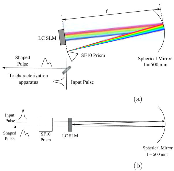
As with other pulse-shaping setups, we make use of Fourier methods to achieve control of the temporal pulse shape. The laser used is a 30 fs, 100 mW, 80 MHz, Ti:Sapphire oscillator. The apparatus is based on a zero dispersion or 4f pulse shaping line [6] using a prism as the dispersive element [14,15]. Our apparatus is a folded, reflective version of the zero dispersion line, as shown in Fig. 1. In this setup, the phase change induced by the SLM is mapped directly to the spectral phase of the pulse. By using an equilateral SF10 prism (near Brewster) we achieve high efficiency. With a dielectric mirror in place of the SLM, this system has a throughput approaching 99%.
Fig. 1.
Schematic of the pulse shaping apparatus as seen (a) from above and (b) from the side. The LC SLM is placed in the Fourier plane of the pulse, where it is used to modify the spectral phase. In (b), note that the height of the pulse is changed using the spherical mirror and the LC SLM.
A pulse shaping system has been previously reported with the same LC SLM. This system used a grating for the dispersive element, and was optimized for spectral resolution and minimum footprint as opposed to throughput [19].
Though based on the zero dispersion pulse shaping line, this apparatus is not truly dispersion free. There is residual dispersion as a result of the prism and the 2 mm thick window of the SLM. In principle, the pulse shaper can be used to compensate for this dispersion. In practice, we use an external prism compressor composed of two matched equilateral SF18 prisms. In this manner, the full dynamic range of the pulse shaper is preserved for our application. The net dispersion of the system (SLM o;) is measured in section 5.
3.3. Spectral resolution
By using a single prism for the dispersive element in the pulse shaping apparatus, we have inherently limited the spot size and therefore the spectral resolution of the apparatus. This is because the prism has a relatively low angular dispersion, resulting in a longer path length to achieve the desired spatial dispersion. The result is a large Rayleigh range for the individual frequencies of the pulse, thus limiting the spot size, according to the equation (where the angle of incidence is equal to the angle of deviation):
| (1) |
where w0 is the 1/e radius of the spot at the focal plane, f is the focal length of the mirror, and wi is the radius of the input beam. Because the bandwidth of the pulses is relatively small (≈ 20 – 30 nm), it is sufficient to assume that the spot size of each wavelength is constant. However, for pulses with very broad spectra (e.g. octave spanning), it is necessary to take spot size of each wavelength into account. To minimize the spot size at the SLM, we expanded the input beam to the largest diameter possible for the aperture of the prism, which is approximately 6 mm at the FWHM. With this apparatus, the FWHM of an assumed Gaussian-intensity profile for the central wavelength of the spectrum was measured to be 84 μm. This large spot size limits the amount of spectral resolution we can achieve according to the equation [7]:
| (2) |
where δω is the spectral resolution, and α(ω) is the spatial dispersion. This spatial dispersion parameter is defined as:
| (3) |
where the variable x represents the spatial coordinate on the SLM face, and the term (dθ/dω) is the angular dispersion of the prism. Note that the small angle approximation has been made here.
In this setup, it is more convenient to define the spatial dispersion in terms of wavelength instead of frequency. This is because we can empirically determine the correspondence between wavelength and pixel number on the LC SLM. This is done by using a known pixel number to steer a wavelength out of the aperture of the system, and measuring the spectrum. Thus we express the spectral resolution of the apparatus (equation 2) as:
| (4) |
where:
| (5) |
The derivative of the index with respect to wavelength is straightforward to calculate using the Sellmeier equation. The term (dθ/dn) was taken from reference [22], but can easily be calculated using Snell’s law. For an equilateral prism, this term simplifies to be:
| (6) |
Therefore, the spatial dispersion of this pulse shaping apparatus is:
| (7) |
This definition of the spatial dispersion can be used to calculate the positions of each wavelength on the LC SLM, allowing for the spectral phase modulation for each wavelength to be calculated for a given pattern written on the SLM.
Equation 4 can be rearranged to obtain:
| (8) |
The spectral resolution was calculated for this setup to be δλ ≈ 1.5 nm, which, as shown in section 6, is in good agreement with the empirically determined value. Equation 8 demonstrates that the spectral resolution of the pulse shaper is dependent upon the input beam radius, and the angular dispersion of the prism. To increase spectral resolution, the input beam size and the angular dispersion can be increased.
4. Spatial characterization of SLM
In order to accurately characterize the apparatus and to be able to make theoretical predictions of shaped pulses, one must have an accurate calibration of the SLM. By obtaining the calibration for the device, it is possible to directly apply desired waveforms to the pulse. This type of open-loop control (as opposed to closed-loop control with genetic algorithms) is often more desirable for applications where the fundamentals of the physical process being excited by the pulse are well understood. Another advantage to obtaining an accurate calibration is that the capabilities of the LC SLM are better understood, such as uniformity of pixel response and hysteresis.
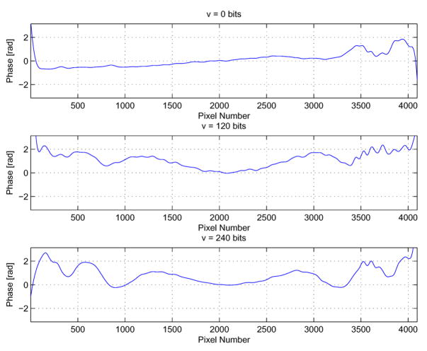
The SLM calibration is often done for different parts of the SLM, then the same calibration curve is used for every pixel. Different methods have been used to obtain the calibration curve. One method uses an amplitude mask, composed of two 100 μm slits in conjunction with a cross-correlation measurement [23]. Another uses a HeNe laser with the modulator placed external to the pulse shaper apparatus, and between crossed polarizers [24,25]. The elements are characterized by measuring the beam transmission as a function of bias voltage. This method showed some non-uniformity in the pixels’ response as a function of voltage (up to 5 % difference). Therefore, to obtain an accurate calibration curve, it is necessary to include the pixel number as a parameter, effectively making the calibration a two-dimensional set of data, namely ϕ(v, p), where v is the 8-bit voltage applied to pixel number p.
To measure the phase shift of all the SLM pixels simultaneously, we use a spatial interferometry setup composed of a Michelson interferometer with the SLM placed at the end of one arm. The laser beam is generated from a Ti:Sapphire oscillator operating in cw mode, and is slightly bigger in diameter than the SLM’s active area, so all pixels’ changes are measured in single shot. The wavelength of the laser is the central wavelength of the pulse’s spectrum (800 nm). The output of the Michelson interferometer is imaged to a CCD camera to record the resultant interference pattern. We image the SLM to the CCD with a singlet lens, and shear the two arms to create fringes. The phase extraction is achieved with a Fourier transform method [26]. When the SLM is o;, we obtain a two-dimensional map of the phase given passively by our SLM, i.e., we get the spatial phase variation from the device. A lineout in the direction along the pixels gives the shape of the SLM face.
To obtain the phase variation across the pixels, we apply constant 8-bit voltages and record the interferograms. The phase modulation from each voltage is then extracted from these interferograms, empirically giving the function ϕ(v = const., p). By ramping the 8-bit voltage from 0-bits to 255-bits in 5-bit intervals, then from 255-bits back to 0-bits, we were also able to determine that this device does not exhibit hysteresis.
As can be seen in Fig. 2, where the phase variation of the central pixel has been set to zero radians, there is some variation in the phase shift as a function of pixel number. Thus, one can modify the spectral phase shape of a pulse by simply applying a constant voltage to the SLM. This effect will be very noticeable the more the SLM face is filled.
Fig. 2.
Phase induced when applying constant voltages on the SLM for three given voltages. Note that we have taken advantage of the arbitrary DC phase shift inherent in the interferometric measurement to shift the center pixel of the SLM to a phase of zero radians.
This calibration method demonstrates the nonuniformity of the device, resulting in a different ϕ(v) calibration for each pixel. It is then necessary to have a characterization tool always present in the pulse shaper to empirically measure the spectral phase we write. This would also allow one to obtain the wavelength dependence of the LC SLM response, which is cumbersome to measure with spatial interferometry at a single wavelength.
For that purpose, we characterized the pulse shaper with a modified version of spectral interferometry that features unprecedented wavelength resolution, the SEA TADPOLE [20,27] method.
5. Spectral characterization of pulse shaper
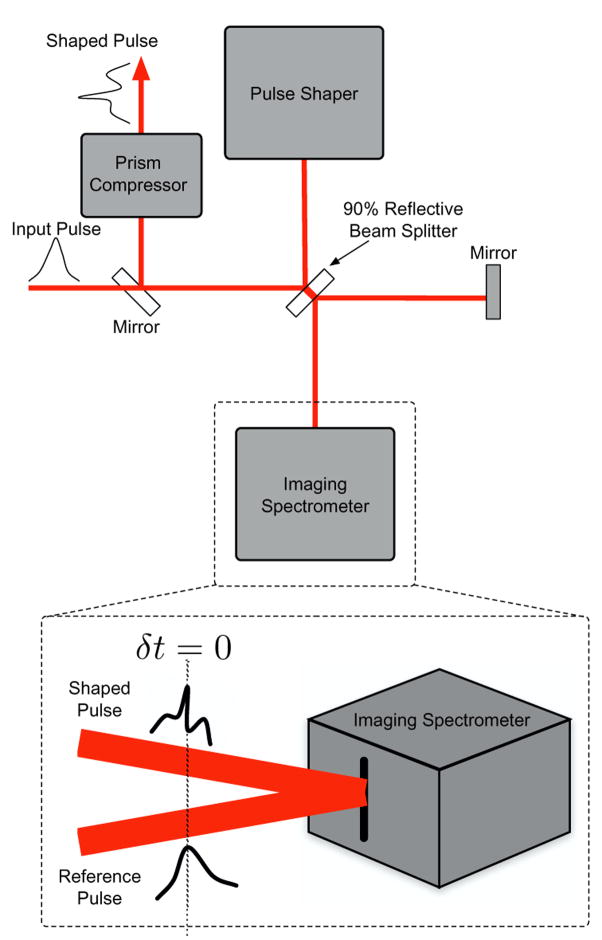
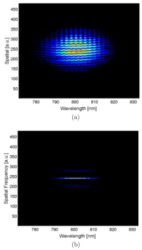
The SEA TADPOLE technique was used to obtain a measurement of the phase variation due to the SLM as a function of wavelength. Whereas other techniques for measuring wavelength dependence of phase variation rely on obtaining only a handful data points in the spectral domain [19], the spectral resolution with SEA TADPOLE is determined by the spectrometer. This is a great advantage, because it allows one to directly measure the spectral phase variation, thus eliminating the need to use a calibration. It also has the significant advantage that it is a linear technique, so only a small amount of light is necessary to monitor the phase variation as a function of wavelength created by the pulse shaping apparatus. This technique works by spectrally resolving the spatial interference of two pulses, as shown in Fig. 3. This is accomplished by placing the pulse shaping apparatus at one arm of a Michelson interferometer with at 90% reflective beamsplitter. The output beams from the interferometer are tilted slightly such that they intersect at the entrance slit of an imaging spectrometer, resulting in an interference signal in the spatial dimension. The path lengths of the arms are perfectly matched so that the pulses overlap in time, thus spectrally resolving the spatial interference. A measured spectral interferogram (SI) is shown in Fig. 4(a).
Fig. 3.
Setup for SEA TADPOLE imaging is simply a Michelson interferometer. One arm of the interferometer is the pulse shaping apparatus, and an imaging spectrometer is used to obtain the interference pattern. The image is created by overlapping the pulses in time, and imaging spatial interference of the pulses at the entrance slit of the interferometer.
Fig. 4.
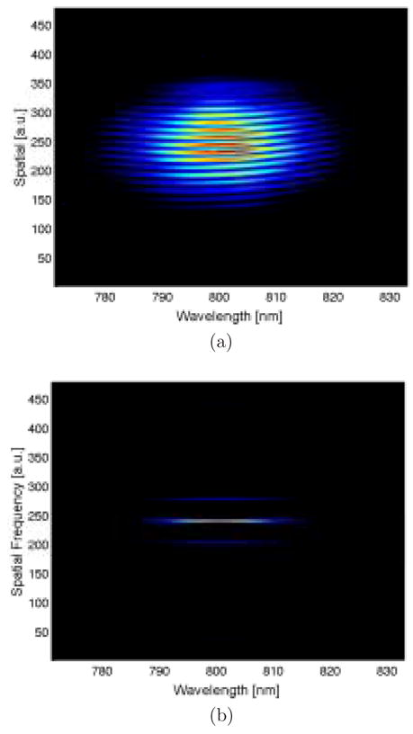
(a) Typical SI with the LC SLM o&. (b) Fourier transform of SI in spatial dimension only.
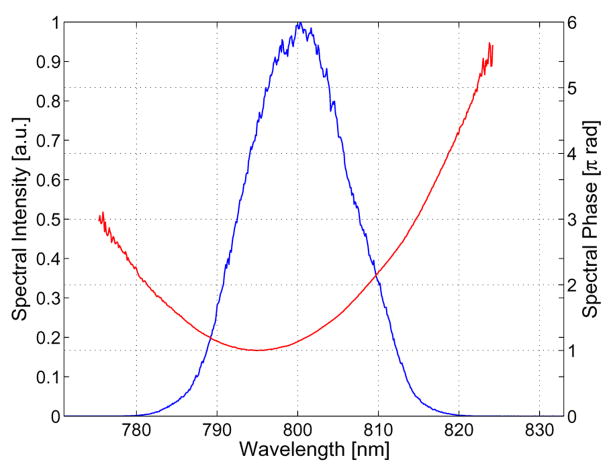
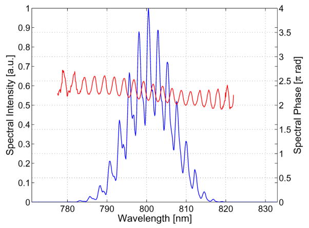
Once the SI is obtained, the image is Fourier transformed along the spatial dimension (Fig. 4(b)). The resulting image contains the phase information about the pulse in the two sidelobes. By taking the complex argument of a lineout of one of the sidelobes, one can extract the spectral phase of the pulse. The spectral phase extracted from the SI shown in Fig. 4(a) is shown in Fig. 5. It can be clearly seen that the pulse shaping line is not truly zero dispersion for the reasons discussed in section 3.2.
Fig. 5.
Spectral phase and complex amplitude extracted from the SI shown in Fig. 4(a). The phase induced by the pulse shaping line can be clearly seen.
By measuring the phase variation due to the pulse shaping apparatus, it is possible to determine the phase written to the pulse by the LC SLM by simply subtracting this DC contribution. Figure 6(a) shows a SI taken with a sinusoidal phase variation written to the SLM. The period of the sinusoid is 63 pixels, or 113.0 μm. Figure 7 shows the spectral phase and complex amplitude extracted from the SI.
Fig. 6.
(a) SI generated with a 63-pixel period sinusoidal phase written to the SLM and (b) the spatial Fourier transform of the SI.
Fig. 7.
Spectral phase change due to the SLM and complex amplitude of output pulse from the SI shown in Fig. 6(a).
The ability to measure the change in phase due to the SLM is quite desirable, especially for use in genetic algorithms [28]. Because the SEA TADPOLE technique gives both the spectral phase and complex amplitude of the pulse, it is possible to use that information to calculate the temporal shape and temporal phase of the pulses as well, and thereby completely characterize the pulse (assuming a well-characterized input pulse).
6. Spectral phase and amplitude modulation
Ideally, this device would be used in a high-resolution setup to achieve phase-only modulation of the pulse, thereby generating the desired pulse shape with essentially no (or minimal) loss of throughput. Phase-only modulation is achieved in this apparatus when the spectral phase written to the pulse varies slowly, i.e., the phase written to the SLM does not have features that are smaller than the spectral resolution of the setup, as discussed in section 3.3.
With phase only modulation, we were able to correct for residual third-order phase induced by the prism compressor. This shortened the pulse duration from 39 fs to 30 fs. More complex pulse shapes can be obtained by either modifying the apparatus to have a higher spectral resolution, or by modulation of the spectral content of the pulse.
In what follows, we characterize the amplitude modulation induced by the LC SLM with SEA TADPOLE in a single shot. For clarity, the measured residual phase (LC SLM o;) is subtracted off to give the spectral phase change induced by the LC SLM.
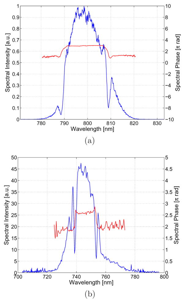
Amplitude modulation occurs with this device when writing a phase function to the SLM with features smaller than the spectral resolution. This is because the phase variation looks like a diffraction grating for the individual frequencies within the pulse, causing them to be diffracted out of the aperture of the system. To measure this effect, we write rectangular phase variations to the SLM. Because the voltage must ramp from 0 bits to 80 bits in a spatial region that is smaller than the spectral resolution, the edges of the phase variation appear to be linear. This steers those frequencies incident upon that portion of the SLM out of the aperture of the system. The result is amplitude modulation, shown in Fig. 8(a) and Fig. 8(b) with rectangular features of widths 500 pixels (900 μm). These figures demonstrate that the pulse shaping system reported here is capable of not only phase modulation, but amplitude modulation as well. This is an important result, because, to our knowledge, this is the first demonstration of spectral phase and amplitude modulation of an ultrashort pulse with a single LC SLM. Note that the bandwidth in these figures are different, because we used a different oscillator for each. The spectral width changes depending on the oscillator, and the width in Fig. 8(b) completely fills the SLM.
Fig. 8.
Examples of amplitude modulation with the SLM. Both figures show the result of a rectangular phase variation 500 pixels in width written to the SLM. In (b) the spectrum is increased, and the input beam diameter is twice that in (a), resulting in twice the spectral resolution. The amplitude modulation occurs when the variation in phase happens quickly. This is the result of the spectral resolution being lower than the resolution of the SLM, thus the phase jump looks like a linear phase ramp for some of the frequencies in the pulse.
Figure 8(a) and Fig. 8(b) also allow for the spectral resolution to be empirically determined. By looking at the width of the spectral hole, an approximate spectral resolution can be determined. In Fig. 8(a), the spectral resolution is approximately 2 nm, which translates into a spatial resolution of 105 μm. (Recall that the spectral resolution was calculated in section 3.3 to be approximately 1.5 nm.) Dividing the spatial resolution by the size of a single pixel, we find that the smallest feature that can be written to the SLM while still maintaining phase-only modulation is 58 pixels. Thus there are 70 degrees of freedom on the entire SLM to maintain phase-only pulse shaping.
In order to demonstrate the scalability of the spectral resolution of this apparatus, we used a different oscillator for Fig. 8(b), which had an input beam diameter (wi) that was twice that used in Fig. 8(a). Based on equation 8, one expects the spectral resolution to be improved by a factor of 2, thereby improving the spatial resolution by a factor of 2 as well, thus doubling the degrees of freedom available for phase-only pulse shaping. From Fig. 8(b), the spectral resolution in this case was determined to be 1 nm, which corresponds to a spatial resolution of 50 μm. Thus the pixel grouping for phase-only modulation in this case is 28 pixels, resulting in 146 degrees of freedom on the LC SLM. It is possible to extend this example even further by further increasing the beam diameter and the angular dispersion (e.g. with more dispersive prisms, or a double-prism setup) to achieve an even better spectral resolution.
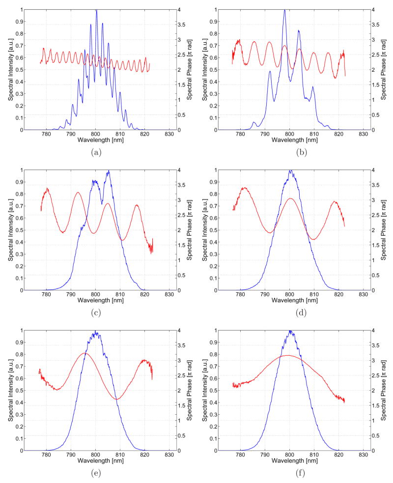
The effect of spectral resolution on amplitude modulation can be demonstrated in a more intuitive way. Shown in Fig. 9 is an array of extracted spectral phases and intensities for various sinusoidal phase variations written to the LC SLM. The only parameter varied in the various subfigures is the period of the sine wave. The effect of the spectral resolution on amplitude modulation is clear. As the phase variations on the SLM become smaller than the spectral resolution, the result is amplitude modulation. As we increase the period, the amplitude modulation decreases until the pulse shaping apparatus is operating in a phase modulation regime. Amplitude modulation leads to undesired loss of energy, which needs to be small enough to be able to take advantage of the gain in energy when using a prism-base pulse shaper. The spectrum from Fig. 9(a) corresponds to an energy throughput of 48%.
Fig. 9.
This figure illustrates the progression from amplitude and phase modulation to phase-only modulation when the period of a sinusoidal phase written to the SLM is varied. The periods are measured in pixels, and for the figures shown are: (a) 63, (b) 157, (c) 314, (d) 471, (e) 628, and (f) 1256. Note that as the period is decreased, the features on the SLM become smaller than the spectral resolution, resulting in amplitude modulation.
These results make it clear how important the spot size, and therefore the spectral resolution, of the pulse shaping apparatus are. Care must be taken in the design of the apparatus to tailor it for different applications.
7. Conclusion
We have demonstrated pulse shaping by spectral phase and amplitude modulation with a single liquid crystal spatial light modulator. The unique construction of the device, as well as the use of a prism for the dispersive element of the pulse shaping line, results in a pulse shaping apparatus capable of providing spectral phase and amplitude modulation with a maximum efficiency of 85%. We have also demonstrated two methods for characterization of the device, one spatially and one spectrally, both in single shot operation. These characterization techniques are well matched to the small pixel size and large number of elements in the LC SLM. High efficiency pulse shaping combined with a technique to measure the spectral phase and amplitude of the pulse with a linear intensity response make this apparatus optimal for pulse shaping applications where amplitude modulation is not problematic.
Acknowledgments
The authors would like to thank Erich Hoover for his assistance with LabVIEW coding.
This work was supported by the National Science Foundation under grant MRI PHY-0420357, and by the NIBIB through grant EB003832. Initial funding for this work was provided by Sandia National Labs.
Footnotes
Publisher's Disclaimer: This is a PDF file of an unedited manuscript that has been accepted for publication. As a service to our customers we are providing this early version of the manuscript. The manuscript will undergo copyediting, typesetting, and review of the resulting proof before it is published in its final citable form. Please note that during the production process errors may be discovered which could affect the content, and all legal disclaimers that apply to the journal pertain.
References
- 1.Bardeen CJ, Yakovlev VV, Squier JA, Wilson KR, Carpenter SD, Weber PM. Effect of pulse shape on the e5ciency of multiphoton processes: Implications for biological microscopy. J Biomed Opt. 1999;4:362–367. doi: 10.1117/1.429937. [DOI] [PubMed] [Google Scholar]
- 2.Kawano H, Nabekawa Y, Suda A, Oishi Y, Mizuno H, Miyawaki A, Midorikawa K. Attenuation of photobleaching in two-photon excitation fluorescence from green fluorescent protein with shaped excitation pulses. Biochem Biophys Res Commun. 2003;311:592–596. doi: 10.1016/j.bbrc.2003.09.236. [DOI] [PubMed] [Google Scholar]
- 3.Hillegas CW, Tull JX, Goswami D, Strickland D, Warren WS. Femtosecond laser pulse shaping by use of microsecond radio-frequency pulses. Opt Lett. 1994;19:737–739. doi: 10.1364/ol.19.000737. [DOI] [PubMed] [Google Scholar]
- 4.Verluise F, Laude V, Cheng Z, Spielmann C, Tournois P. Amplitude and phase control of ultrashort pulses by use of an acousto-optic programmable dispersive filter: pulse compression and shaping. Opt Lett. 2000;25:575–577. doi: 10.1364/ol.25.000575. [DOI] [PubMed] [Google Scholar]
- 5.Heritage J, Thurston R, Weiner A. Picosecond pulse shaping by spectral phase and amplitude manipulation. Opt Lett. 1985;10:609–611. doi: 10.1364/ol.10.000609. [DOI] [PubMed] [Google Scholar]
- 6.Weiner AM, Heritage JP, Kirschner EM. High-resolution femtosecond pulse shaping. J Opt Soc Am B. 1988;5:1563–1572. [Google Scholar]
- 7.Weiner AM. Femtosecond pulse shaping using spatial light modulators. Rev Sci Imstrum. 2000;71:1929–1960. [Google Scholar]
- 8.Zeek E, Bartels R, Murnane MM, Kapteyn HC, Backus S, Vdovin G. Adaptive pulse compression for transform-limited 15-fs high-energy pulse generation. Optics Lett. 2000 April;25(8):587–589. doi: 10.1364/ol.25.000587. [DOI] [PubMed] [Google Scholar]
- 9.Treacy EB. Optical pulse compression with diffraction gratings. IEEE J Quantum Electronics. 1969 September;5(9):454–458. [Google Scholar]
- 10.Heritage J, Thurston R, Thomlinson W, Weiner A. Spectral windowing of frequency-modulated optical pulses in a grating compressor. Appl Phys Lett. 1985 May;47(2):87–89. [Google Scholar]
- 11.Weiner AM, Heritage JP, Salehi JA. Encoding and decoding of femtosecond pulses. Optics Lett. 1988 April;13(4):300–302. doi: 10.1364/ol.13.000300. [DOI] [PubMed] [Google Scholar]
- 12.Dantus M, Lozovoy VV. Experimental coherent laser control of physicochemical processes. Chem Rev. 2004;104:1813–1859. doi: 10.1021/cr020668r. [DOI] [PubMed] [Google Scholar]
- 13.Goswami D. Optical pulse shaping approaches to coherent control. Physics Reports. 2003 September;374:385–481. [Google Scholar]
- 14.Xu L, Nakagawa N, Morita R, Shigekawa H, Yamashita M. Programmable chirp compensation for 6-fs pulse generation with a prism-pair-formed pulse shaper. IEEE J Quantum Electronics. 2000 August;36(8):893–899. [Google Scholar]
- 15.Binhammer T, Rittweger E, Morgner U, Ell R, Kärtner FX. Spectral phase control and temporal superresolution toward the single-cycle pulse. Opt Lett. 2006;31:1552–1554. doi: 10.1364/ol.31.001552. [DOI] [PubMed] [Google Scholar]
- 16.Lindner F, Paulus GG, Grasbon F, Dreischuh A, Walther H. Dispersion control in a 100-khz-repetition-rate 35-fs ti: Sapphire regenerative amplifier system. IEEE J Quant Elec. 2002 November;38(11):1465–1470. [Google Scholar]
- 17.Brixner T, Krampert G, Niklaus P, Gerber G. Generation and characterization of polarization-shaped femtosecond laser pulses. App Phys B. 2002;74:S133–S144. [Google Scholar]
- 18.Monmayrant A, Chatel B. New phase and amplitude high resolution pulse shaper. Rev Sci Instr. 2004;75(8) [Google Scholar]
- 19.Postma S, van der Walle P, Offerhaus H, val Hulst N. Compact high-resolution spectral phase shaper. Rev Sci Instrum. 2005;76 [Google Scholar]
- 20.Bowlan P, Gabolde P, Shreenath A, McGresham K, Trebino R. Crossed-beam spectral interferometry: a simple, high-spectral-resolution method for completely characterizing complex ultrashort pulses in real time. Optics Express. 2006 November;14(24):11892–11900. doi: 10.1364/oe.14.011892. [DOI] [PubMed] [Google Scholar]
- 21.Serati S, Stockley J. Advanced liquid crystal on silicon optical phased arrays. Aerospace Conference Proceedings. 2002;3:3-1395–3-1402. [Google Scholar]
- 22.Thorne AP. Spectrophysics. 2. Chapman and Hall; 1988. [Google Scholar]
- 23.Weiner AM, Leaird DE, Patel JS, Wullert JR. Programmable femtosecond pulse shaping by use of a multielement liquid-crystal phase modulator. Opt Lett. 1990;15:326–328. doi: 10.1364/ol.15.000326. [DOI] [PubMed] [Google Scholar]
- 24.Weiner AM, Leaird DE, Patel JS, John I, Wullert R. Programmable shaping of femtosecond optical pulses by use of 128-element liquid crystal phase modulator. IEEE J Quantum Electron. 1992;28:908–920. [Google Scholar]
- 25.Efimov A, Schaffer C, Reitze D. Programmable shaping of ultrabroad-bandwidth pulses from a ti:sapphire laser. J Opt Soc Am B. 1995;12:1968–1980. [Google Scholar]
- 26.Takeda M, Ina H, Kobayashi S. Fourier-transform method of fringe-pattern analysis for computer-based topography and interferometry. J Opt Soc Am. 1982;72:156–160. [Google Scholar]
- 27.Meshulach D, Yelin D, Silberberg Y. Real-time spatial-spectral interference measurements of ultrashort optical pulses. J Opt Soc Am B. 1997;14:2095–2098. [Google Scholar]
- 28.Dorrer C, Salin F, Verluise F, Huignard J. Programmable phase control of femtosecond pulses by use of a nonpixelated spatial light modulator. Opt Lett. 1998;23:709–711. doi: 10.1364/ol.23.000709. [DOI] [PubMed] [Google Scholar]


