

Abstract
In this work we present an inverse finite-element modeling framework for constitutive modeling and parameter estimation of soft tissues using full-field volumetric deformation data obtained from 3D ultrasound. The finite-element model is coupled to full-field visual measurements by regularization springs attached at nodal locations. The free ends of the springs are displaced according to the locally estimated tissue motion and the normalized potential energy stored in all springs serves as a measure of model-experiment agreement for material parameter optimization. We demonstrate good accuracy of estimated parameters and consistent convergence properties on synthetically generated data. We present constitutive model selection and parameter estimation for perfused porcine liver in indentation and demonstrate that a quasilinear viscoelastic model with shear modulus relaxation offers good model-experiment agreement in terms of indenter displacement (0.19 mm RMS error) and tissue displacement field (0.97 mm RMS error).
Keywords: liver mechanics, finite-element method, parameter identification, inverse method, optical flow, image-guided surgery
1 Introduction
Computational models of organ and tissue mechanical response are beginning to play a significant role in modern computerized medicine and have become integral components of image-guided surgery and interventions (Carter et al., 2005; Clatz et al., 2005; DiMaio and Salcudean, 2005; Alterovitz et al., 2006; Cash and et al., 2007; Archip et al., 2007). Such image-guided tasks require close interplay of computational biomechanical models with preoperative and intraoperative imaging. The development of appropriate models is challenging for two reasons. The first difficulty lies in the formulation of a suitable constitutive law capable of capturing the large-strain, nonlinear, viscoelastic response of tissues. The second challenge involves the development of experimental testing protocols appropriate for unique identification of the material parameters. In addition, the significant subject-to-subject variability contributes to a strong need for patient-specific (personalized) models, which may be generated and parameterized with clinically feasible testing protocols.
Material properties of soft tissues vary significantly between in vivo and in vitro settings (Fung, 1993; Miller and Chinzei, 1997; Miller et al., 2000; Gefen and Margulies, 2004; Miller, 2005; Kerdok et al., 2006). Current in vivo soft tissue testing is dominated by indentation due to the limited access requirements, simplicity of the instrumentation, and low risk of injury associated with the procedure (Balakrishnan and Socrate, 2007). The single force-displacement history obtained during conventional indentation experiments is governed by the mechanical response of the whole material domain, combining near-field (large strain) and far-field (low strain) contributions. Much of the information related to the interplay between shear and bulk compliance in the complex deformation field beneath the indenter is lost when capturing this single output. Therefore, supplemental experimental methods, such as secondary indentation sensors (Balakrishnan and Socrate, 2007), tissue surface tracking (Einstein et al., 2005; Evans et al., 2007), or independent tests of bulk compliance (i.e. confined tissue compression) are necessary for well-conditioned parameter identification. Image-based characterization methods are a promising solution, as they provide the means for noninvasive, in vivo estimation of material parameters and offer improved sensitivity and uniqueness of recovered parameters.
In this paper, we propose a general inverse finite-element modeling framework for constitutive modeling and parameter estimation of soft tissues using full-field volumetric deformation data obtained from 3D ultrasound. We validate the parameter estimation method on synthetically generated data and perform constitutive model selection for perfused porcine liver in indentation. While we limit our investigation to an experimental protocol which involves a single indenter displacement rate, the volumetric imaging captures local tissue strain rates in the range from zero to the maximum rate beneath the indenter. By exploring agreement with the image-based internal tissue displacement field, we determine an appropriate constitutive law and material parameters, which capture the time-dependent response of the tissue.
2 Methods
In this paper we describe a liver indentation experimental system and an inverse finite-element modeling framework, which takes advantage of concurrent image data obtained from 3D ultrasound imaging. While the liver is an inhomogeneous organ with complex anatomical structure, our model approximates it as a homogeneous and isotropic material. The characteristic length of the hepatic lobules, the functional units of the organ, is on the order of 1 mm. Therefore, the concept of homogenizing the tissue is justifiable for deformation fields applied over longer length scales (approximately 1 cm). In this work we also neglect the effects of the liver capsule and minimize the contributions from vasculature by examining the parenchyma with 3DUS and avoiding the placement of the indenter over large vessels. The proposed approach relies on the following components: experimental indentation apparatus, volumetric imaging system, a nonrigid registration algorithm for deformation field estimation, and a nonlinear parameter optimization algorithm. The design considerations and performance of each component are described in the following sections. In addition, we present a validation study and an application of this framework to constitutive modeling of perfused porcine liver in indentation.
2.1 Experimental Setup
Liver Perfusion Apparatus
Due to changes in the liver’s mechanical properties ex vivo (Kerdok, 2006; Nava et al., 2007), it is important to measure the organ response in its physiological conditions. Measurement of boundary conditions and instrument access are often the limiting factors in in vivo testing. To address these challenges, we used an ex vivo perfusion system, described by Kerdok (2006) and depicted in Figure 1. This system allowed us to perform organ tests with control of boundary conditions and near in vivo tissue state. The whole porcine liver was perfused with a heated perfusate (five liters of Dextrose 5% Lactated Ringers Solution (D5RL) and one liter of 6% Hetastarch (Henry Schein, Melville, NY)) under physiologic pressures, with a mean portal venous pressure of 7.98 mmHg, a mean hepatic arterial pressure of 94.77 mmHg, and at a mean temperature of 33 °C.
Fig. 1.

Left: liver perfusion system. Right: the experimental arrangement showing the indenter at the top surface of the organ and the 3DUS probe beneath the organ.
Following the experimental protocol described in Kerdok et al. (2006) and Kerdok (2006), the liver was indented at 2 mm/s to a depth of 9.2 mm with a 12 mm diameter, flat, cylindrical indenter actuated by Electroforce ELF 3200 (Bose Corporation EnduraTEC Systems Group, Minnetonka, MN, USA) material testing system. The system measures displacement using a linear variable differential transformer (Schaevitz MHR-250, Measurement Specialties, Hampton, VA, USA) with ± 6.3 mm travel (0.559 μm RMS alone, 3.9 μm RMS with controller), force using a 22 N submersible load cell (0.49 mN RMS alone, 13 mN RMS with controller) (Honeywell Sensotec Sensors Model 31, Columbus Ohio), and acceleration using a ± 50 g accelerometer (0.024 V RMS alone, 0.204V RMS with controller) (Kistler, Amherst, NY, USA).
Volumetric Imaging
The volumetric deformation was imaged with the 3D ultrasound probe (SONOS 7500, Philips Medical Systems, Andover, MA, USA) placed below the tissue sample, as shown in Fig. 1. The 2–4 MHz probe acquires data at the rate of 26 frames per second, which is subsequently streamed over an Ethernet connection to a PC workstation for storage and processing. The transducer was operated at a 7 cm depth of focus to provide sufficient field of view, which contains the organ surface, parenchyma, and the probe stand-off pad. The resulting volumetric frames were rasterized at 128×48×204 voxels, corresponding to an axial resolution of approximately 0.3 mm/voxel and a lateral resolution of 0.5 mm/voxel. Two-dimensional image slices of the volumetric sequence and the associated indenter force and displacement histories, acquired during a 2 mm/s load/unload cycle, are shown in Figure 2.
Fig. 2.

The indenter force and displacement histories and force-displacement indentation response, acquired during 2 mm.s−1 load/unload cycle. The associated 2D slices through the 3DUS sequence are shown at the bottom.
2.2 Nonrigid Image Registration and Full-Field Constitutive Modeling
We use a nonrigid registration scheme (Fig. 3), described in further detail in Jordan et al. (2008), to estimate the deformation field captured by the concurrent 3DUS imaging. The volumetric image data obtained during organ indentation contains relatively slow deformations (maximum tissue displacement is less than 0.3 voxels per frame) and the liver parenchyma produces rich textural content under 3DUS (see Figure 2). Given these conditions, the algorithm achieves good accuracy and robustness. In Jordan et al. (2008) we demonstrate the accuracy against manually tracked tissue landmarks (mean magnitude error of less than 0.6mm) in ex vivo liver indentation and present a quantitative error analysis using synthetic deformation sequences.
Fig. 3.

In the nonrigid image registration framework, sparse local motion estimates uOF are coupled to a mechanical finite-element model as lumped body forces applied by displaced regularization springs. This results in a mechanically constrained deformation field uF EM and regularization energy Φ.
In the proposed nonrigid image registration scheme, sparse image-based local motion estimates uOF and associated confidence cOF are estimated with an adaptation of the Lucas and Kanade (1981) optical flow algorithm described in Appendix A. These local motion estimates are enforced as concentrated forces applied at the nodes of a deformable finite-element organ model, enforcing physically admissible deformations. The concentrated forces are generated by regularization springs, connected to the mesh nodes, as their free ends are displaced according to local motion estimates. The choice of each regularization spring stiffness reflects local textural quality and associated local motion confidence. This approach not only provides regularized estimate of organ deformation field (uF EM) but also offers a measure of model/experiment agreement in the form of normalized potential energy (Φ) contained in regularization springs. The displacement field uF EM is the equilibrium field computed by the finite-element solver, minimizing the total potential energy of the system, which includes the strain energy stored in the continuum model and the potential energy in the regularization springs. Consequently, noisy uF EM fields are penalized by the strain energy associated with the high local displacement gradients of the continuum model and excessively smoothed uF EM fields are penalized by the increased potential energy of the regularization springs defined as
| (1) |
where j = {x, y, z}, N is the number of attached regularization springs, is the spring stiffness, and the spring distension is defined as . In order to relate the image-based confidence values to physically relevant springs stiffnesses, each stiffness is obtained not only as a function of local image texture, but also of the local nodal stiffness of the mechanical model. Therefore, the stiffness of each regularization spring is computed as
| (2) |
where i is the node index, β is the regularization coefficient, and is the global stiffness of node i in direction j (obtained from the diagonal members of the global stiffness matrix).
The image registration framework is suitable for two types of fundamentally different applications. In the first category of applications, the framework may be used to obtain a mechanically admissible image registration, such as between preoperative and intraoperative images. In these applications the biomechanical model and the image similarity term are coupled via the regularization springs to provide mechanically consistent internal organ deformations. Examples of such applications include the intraoperative brain shift, tumor localization, mammogram registration, etc. The second category consists of applications in constitutive organ response characterization. When external forces and boundary conditions are known or experimentally measured, the registration framework may be used to optimize the consistency between the chosen biomechanical model and the experimental images. When measuring the constitutive response of an organ, an objective function Φ (pn) derived from the springs potential energy US, may be defined as
| (3) |
and serves as an appropriate measure of model-experiment agreement. The energy is normalized by the nodal stiffness to prevent artificial bias towards compliant models. Additionally, the spring energy is normalized by the regularization coefficient β. This parameter determines the image-mechanics coupling balance in the conventional image registration applications. When modeling the constitutive response of an organ, we seek to identify mechanical models which are consistent with the local unregularized motion estimates uOF. Therefore, the choice of parameter β does not affect the model-experiment fitting 1. Using the objective function Φ (pn) defined in Eq. 3, imperfect models are associated with higher levels of regularization energy. The magnitude of the regularization energy, therefore, can be considered a measure of the accuracy of a constitutive formulation, and minimization algorithms can be used to determine optimal material parameters.
In our experimental configuration, the force and displacement histories at the tip of the indenter are acquired with higher accuracy and lower noise in comparison to the optical flow measurements. To incorporate these sensor measurements into the optimization framework, we define an objective function Φ̇, which is the sum of a volumetric error term Φ̇vol and an indenter error term Φ̇ind defined as
| (4) |
and
| (5) |
The volumetric error term Φ̇vol is the mean squared difference between the optical flow and the model velocity fields over the time period T normalized by the number of regularization springs N. The indenter error term Φ̇ind is the mean squared difference between the vertical indenter velocity and the modeled indenter velocity . Such definition of the objective function scales the two error components to comparable magnitudes and aids in obtaining model fits consistent with experimental tissue displacement field as well as the indenter force-displacement history.
Throughout this paper, we chose to use indenter and nodal velocity histories as the measure of model-experiment agreement. Objective functions based on velocity-based or displacement-based model-experiment agreement are both suitable choices for model optimization. The differential optical flow estimates are frame-to-frame displacement estimates (not absolute). Therefore, small estimation errors may contribute to more significant accumulation error (Lim and El Gamal, 2001) when integrated over long periods of time. For this reason, we determined the velocity fields as the more appropriate choice and were able to confirm their improved convergence properties.
Liver Finite-Element Model
The perfused ex vivo liver is modeled with a finite-element model implemented in a commercial FE solver (ABAQUS 6.7, Simulia, Providence, RI, USA). The model has a simplified cylindrical geometry (10.0 cm diameter, 3.03 cm height) shown in Fig. 4, as most of the contributions to the indentation response are assumed to be local and not significantly dependent on the whole organ geometry. The mesh is generated automatically with increased density beneath the indenter and consists of 1424 nodes and 804 quadratic tetrahedral elements. The bottom surface of the organ is fully constrained, while the upper and side surfaces are assumed to be stress-free boundaries. The force at the tip of the indenter is prescribed to match the indentation force history obtained experimentally.
Fig. 4.

The deforming finite-element liver model with simplified cylindrical geometry, experimentally measured boundary conditions, and a coregistered 3DUS sequence.
2.3 Method Validation: Synthetic Volumetric Data
To evaluate the sensitivity of the testing method to material parameters, accuracy of the parameters recovered, and to assess the convergence characteristics of the optimization scheme, we conducted a parameter identification study on a synthetically generated 3DUS sequence. We computed a ground-truth deformation field from a forward finite-element model of the indentation experiment with assumed constitutive law and material parameters. We used a high density mesh (4281 nodes, 2706 quadratic tetrahedral elements) in the forward model to minimize field discretization artifacts. The boundary conditions of the forward model were prescribed to match the boundary conditions of the real experimental procedure. The displacement and force histories at the tip of the indenter were recorded to mimic the measurements obtained during the ex vivo experimental procedure. The resulting deformation field was used to warp a reference 3DUS volume, generating a sequence of 100 volumes. The reference 3DUS volume is a single frame acquired by imaging perfused ex vivo liver. Consequently, the generated volumetric sequence preserves the true texture and intensity distribution of liver parenchyma under 3DUS. This synthetic study, however, excludes image artifacts and noise contributions from the imaging sensor.
Biphasic Poroelastic Constitutive Law
To mimic the nonlinear viscoelastic response of the perfused porcine liver, we use a biphasic (mixture theory) constitutive model (Suh and Spilker, 1994; Zhu and Wang, 1998). Biphasic models account for viscous material effects through momentum exchange effects between the solid and fluid phases. The solid phase is formulated through the 2nd-order reduced polynomial strain-energy defined as
| (6) |
where C1, C2, and D1 are the material parameters, I1 is the 1st stretch invariant, and Jel is the elastic volumetric stretch. The flux of the fluid phase is governed by Darcy’s law expressed as
| (7) |
where q is the flux, κ is the permeability coefficient, and ∇P is the fluid pressure gradient.
Using the synthetic 3DUS sequence and force-displacement indentation histories, we perform material parameter estimation in a way that is identical to the approach used with true experimental liver measurements. The geometry and boundary conditions of the FE model used in this inverse process reflect the assumed experimental conditions. The indentation force F(t) is applied at the tip of the indenter, and the bottom surface of the organ is fully constrained. We initialize material parameters with feasible parameter estimates and use a nonlinear optimization algorithm, a bounded downhill simplex method (Lagarias et al., 1998), to iteratively evolve the material parameters (C1, C2, D1, κ) and minimize the objective function Φ̇(pn).
Quasilinear viscoelastic Constitutive Law
In the second synthetic parameter recovery study we perform parameter identification using an alternative constitutive material law, a 2nd-order reduced form polynomial hyperelastic law with a Prony series relaxation of the shear modulus (Holzapfel, 2000; Hibbit et al., 2007). The hyperelastic strain energy of this constitutive law defined in Eq. 6 and the relaxation of the shear modulus G(t) is captured by a 1st-order Prony series
| (8) |
where G0 is the instantaneous shear strain modulus (computed from Eq. 6), G0g∞ is the equilibrium shear strain modulus, g1 = 1 − g∞ is the relative amplitude of the relaxation, and τg1 is the relaxation time constant. The biphasic poroelastic constitutive law governing the response of the synthetic deformation is known to exhibits bulk relaxation. We evaluate the volumetric agreement with a shear relaxation constitutive law to demonstrate the ability to distinguish between materials with inherently different modes of relaxation. We also evaluate the method’s ability to consistently converge to the best possible fit under the given assumptions.
2.4 Perfused Porcine Liver Constitutive Modeling
We perform constitutive modeling of perfused porcine liver in indentation (2 mm.s−1 load/unload cycle) using the proposed inverse modeling framework. We constrain our attention to the 2nd-order reduced polynomial hyperelastic form
| (9) |
and shear and bulk relaxation components
| (10) |
| (11) |
Under this general form, we explore 5 constitutive laws. In the shear relaxation variant (SR), the relaxation of the tissue is assumed to be captured by the relaxation of the instantaneous shear modulus. The bulk compliance is assumed to be linear (D2 = 0) and no bulk relaxation is permitted (k1 = 0). In the subsets SRlow and SRhigh we enforce low (D1 = 1.0 × 10⁻⁴) and high (D1 = 3.0 × 10⁻³) bulk compliance, respectively, to investigate the effects of bulk compliance on the full-field deformation fields.
To investigate the role of bulk relaxation we consider two additional constitutive laws. First, we consider a bulk relaxation (BR) model with 2nd- order bulk compliance and no shear relaxation (g1 = 0). Second, we considered the full constitutive law (SBR) with relaxation of both bulk and shear moduli.
3 Results
3.1 Method Validation: Synthetically Generated Volumetric Data
Biphasic Poroelastic Constitutive Law
Using the synthetically generated deformation sequence governed by biphasic poroelastic constitutive law, the parameter estimation framework consistently converges to the ground-truth parameter values. The evolution of the objective function during the optimization processes seeded from 3 distinct points in the parameter space is shown in Fig. 5, left. The convergence of the material parameters for all 3 seeds is shown in Fig. 5, right. These results are summarized in Table 1 and demonstrate that in the absence of imaging noise (a consequence of synthetic data) the method converges consistently and recovers both bulk and shear response parameters with good sensitivity.
Fig. 5.

Biphasic poroelastic CL: regularization energy evolution (left) and material parameter evolution (right) during material parameter identification seeded from 3 different locations in the parameter space.
Table 1.
Biphasic poroelastic CL: recovered material parameters and associated regularization energy obtained from 3 independent parameter seed points (initial parameter values shown in parentheses). Ground-truth values: C1 = 200, C2 = 5000, D1 = 1.5 × 10⁻⁴, κ = 1.0 × 10⁻⁷
| Parameter | Seed 1 | Seed 2 | Seed 3 |
|---|---|---|---|
| C1 | 193.6 (150) | 192.4 (300) | 192.7 (200) |
| C2 | 4,998 (4,000) | 4,999 (6,000) | 5,014 (5,000) |
| D1 | 1.53 × 10⁻³ (2.0 × 10⁻⁴) | 1.53 × 10⁻³ (5.0 × 10⁻³) | 1.53 × 10⁻³ (1.5 × 10⁻³) |
| κ | 0.96 × 10⁻⁷ (1.0 × 10⁻⁸) | 0.93 × 10⁻⁷ (5.0 × 10⁻⁷) | 0.95 × 10⁻⁷ (1.0 × 10⁻⁷) |
|
| |||
| Φ̇ | 2.63× 10⁻⁶ (6.39 × 10⁻⁶) | 2.63 × 10⁻⁶ (9.10 × 10⁻⁶) | 2.63 × 10⁻⁶ (2.65 × 10⁻⁶) |
| Φ̇ind | 1.08× 10⁻⁸ (2.54 × 10⁻⁶) | 1.23 × 10⁻⁸ (5.12 × 10⁻⁶) | 1.22 × 10⁻⁸ (1.70 × 10⁻⁸) |
| Φ̇vol | 2.62× 10⁻⁶ (3.85 × 10⁻⁶) | 2.62 × 10⁻⁶ (3.98 × 10⁻⁶) | 2.62 × 10⁻⁶ (2.63 × 10⁻⁶) |
Quasilinear Viscoelastic Constitutive Law
The parameter estimation of the quasilinear viscoelastic constitutive law using the deformation sequence with assumed biphasic poroelastic response is summarized Fig. 6 and Table 2. These results suggest that the method converges consistently for all 3 seed points and is able to obtain excellent indenter response agreement with the ground-truth data (see Fig. 7). However, when comparing the magnitudes of the volumetric error, this form of constitutive law offers lesser volumetric agreement with the data. This point is further illustrated by comparing the nodal velocities of the poroelastic (PE), viscoelastic (VE), and optical flow data in Fig. 8. Since the PE model corresponds to the ground-truth deformation, Fig. 8 demonstrates the volumetric disparity of the VE model. In addition, the good agreement of the optical flow estimates with the PE model serves as a validation of the motion estimation scheme (in the absence of imaging system noise). In addition, it serves as a basis for measuring the noise floor of the motion estimation system. Minor oscillations in the optical flow estimates may be observed at some nodes due to voxel-to-element correspondence effects near the model boundary.
Fig. 6.

Quasilinear viscoelastic CL: regularization energy evolution (top left) and material parameter evolution during material parameter identification seeded from 3 different locations in the parameter space.
Table 2.
Viscoelastic CL - recovered material parameters and associated regularization energy obtained from 3 independent parameter seed points (initial parameter values shown in parentheses).
| Parameter | Seed 1 | Seed 2 | Seed 3 |
|---|---|---|---|
| C1 | 23.1 (200) | 24.9 (500) | 23.1 (50) |
| C2 | 2,039 (5,000) | 2,048 (1,000) | 2,030 (6,000) |
| D1 | 2.25 × 10⁻⁴ (1.5 × 10⁻³) | 2.27 × 10⁻⁴ (1.0 × 10⁻⁴)) | 2.24 × 10⁻⁴ (5.0 × 10⁻⁵) |
| g1 | 0.392 (0.400) | 0.398 (0.600) | 0.394 (0.200) |
| τ1 | 0.059 (0.100) | 0.058 (0.500) | 0.059 (0.010) |
|
| |||
| Φ̇ | 1.57× 10⁻⁵ (1.90 × 10⁻⁵) | 1.51 × 10⁻⁵ (1.07 × 10⁻⁴) | 1.56 × 10⁻⁵ (6.01 × 10⁻⁵) |
| Φ̇ind | 9.32× 10⁻⁶ (1.13 × 10⁻⁵) | 8.82 × 10⁻⁶ (9.87 × 10⁻⁵) | 9.18 × 10⁻⁶ (5.54 × 10⁻⁵) |
| Φ̇vol | 6.39× 10⁻⁶ (7.79 × 10⁻⁶) | 6.32 × 10⁻⁶ (7.79 × 10⁻⁶) | 6.38 × 10⁻⁶ (4.69 × 10⁻⁶) |
Fig. 7.
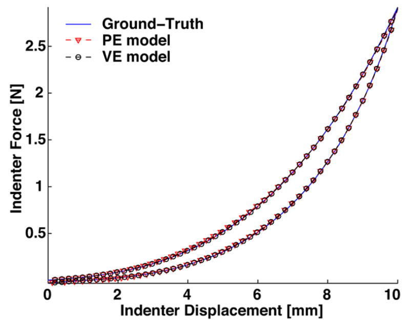
The force-displacement indentation response of the poroelastic model (PE) and viscoelastic model (VE) showing excellent agreement with ground-truth data.
Fig. 8.

Ground-truth deformation sequence: mesh node velocity histories of the poroelastic (PE) and viscoelastic (VE) models compared to optical flow estimates. Only the vertical component of velocity is shown. The selected nodes are within 10 mm of the slice shown.
3.2 Perfused Porcine Liver Constitutive Modeling
The results of the constitutive modeling of perfused porcine liver are summarized in Table 3 and Fig. 9. Several observations should be noted regarding the methods ability to characterize the material response and its contributions in the constitutive law selection process.
Table 3.
Perfused porcine liver: estimated material parameters for the 5 constitutive laws considered.
| Parameter | SRlow | SRhigh | SR | BR | SBR |
|---|---|---|---|---|---|
| C1 | 4.3 | 185.4 | 79.2 | 83.9 | 71.6 |
| C2 | 47.0 | 612.6 | 257 | 40.9 | 218.3 |
| D1 | 1.0 × 10⁻⁴ | 3.0 × 10⁻³ | 4.38 × 10⁻⁴ | 4.71 × 10⁻⁴ | 3.65 × 10⁻⁴ |
| D2 | - | - | - | 2.22 × 10⁻⁵ | 6.7 × 10⁻³ |
| g1 | 0.967 | 0.779 | 0.832 | - | 0.794 |
| τg1 | 0.585 | 0.168 | 0.150 | - | 0.203 |
| k1 | - | - | - | 0.890 | 0.032 |
| τk1 | - | - | - | 0.134 | 0.176 |
|
| |||||
| Φ̇ | 3.52 × 10⁻⁵ | 2.25 × 10⁻⁵ | 2.15 × 10⁻⁵ | 3.08 × 10⁻⁵ | 2.20 × 10⁻⁵ |
| Φ̇ind | 1.52× 10⁻⁷ | 1.69 × 10⁻⁷ | 1.31 × 10⁻⁷ | 1.58 × 10⁻⁷ | 1.35 × 10⁻⁷ |
| Φ̇vol | 3.51 × 10⁻⁵ | 2.24 × 10⁻⁵ | 2.14 × 10⁻⁵ | 3.06 × 10⁻⁵ | 2.19 × 10⁻⁵ |
Fig. 9.

Perfused liver sequence: indentation histories (top, middle) are virtually identical between SR, SRlow, and SRhigh. The SR model provides significantly improved volumetric agreement illustrated with vertical node velocity histories.
The results of the quasilinear viscoelastic constitutive law with shear modulus relaxation (SR) demonstrate that the proposed parameter identification method is capable of recovering the linear bulk compliance parameter D1, which is not observable in conventional indentation tests. While the indentation response (Fig. 9 top middle) is nearly identical for all three SR models, the volumetric nodal velocities differ significantly. This disparity is captured by comparing the SR model’s volumetric error term (Φ̇vol = 2.15 × 10⁻⁵) to the SRlow (Φ̇vol = 3.52 × 10⁻⁵) and SRhigh (Φ̇vol = 2.25 × 10⁻⁵) models with assumed low and high bulk compliance D1, respectively. These findings indicate that estimating the bulk compliance parameter D1 from the full-field deformation data maximizes the volumetric model/experiment agreement.
The parameter identification results using the BR and SBR models suggest that bulk modulus relaxation does not significantly improve the model fit (Φ̇vol = 3.8 × 10⁻⁵ for BR, Φ̇vol = 2.20 × 10⁻⁵ for SBR). For this mode and rate of deformation the simple SR constitutive form is able to account for the material response both at the indenter as well as volumetrically (within the precision of the imaging and deformation tracking systems).
The agreement between the model and the experiment was also quantified in terms of the root mean squared (RMS) error of the indenter and of the nodal displacement histories. While nodal velocity mean squared error (MSE) was found to be the more appropriate objective function choice for model optimization, the nodal displacement RMS errors provide an intuitive measure of the model-experiment agreement. Under this metric, the SR model offers good indenter displacement agreement (0.19 mm RMS error) and volumetric deformation agreement (0.97 mm axial RMS error).
4 Conclusions
In this paper we presented a method for constitutive model selection and parameter identification using real-time 3DUS volumetric imaging. This approach enriches the traditional force-displacement indentation response with the measurement of volumetric deformation and provides good sensitivity to parameters governing the bulk response of the material. These parameters are otherwise not observable in conventional indentation. The ability to decouple the bulk and shear components of the deformation is important and we demonstrated that we can reconstruct the parameters with precision and repeatability in a validation study. Furthermore, the measurement of full volumetric deformation histories offers the ability to observe material response over a range of strain rates. While the indenter is driven at a chosen displacement rate, the local material strain rates throughout the tissue sample vary from zero in the far-field to the maximum levels beneath the indenter. The proposed method is independent of imaging modality and constitutive law, suggesting potential applications for other tissues and scales (i.e. nanoindentation, confocal microscopy, etc.).
The proposed approach is a useful tool for constitutive model selection, as suggested in our porcine liver indentation modeling. The best experimental fits were attained with a quasilinear viscoelastic model with 2nd-order reduced polynomial instantaneous response and a Prony series relaxation of the bulk and shear moduli. Using the full-field measurements, we demonstrated that a simpler constitutive form with shear relaxation provides comparable model-experiment agreement. This observation suggests that shear relaxation is the dominant mode of relaxation for liver in indentation and that the SR model is appropriate (considering the reduced number of parameters).
One of the advantages of the proposed method is the ease of application in in vivo settings. The knowledge/observation of boundary condition is one of the chief motivating factors for ex vivo testing. Imaging the organ during indentation testing, however, offers the ability to observe the in vivo boundary conditions and account for them during the inverse modeling process. Direct in vivo indentation tests of the liver can be performed in the operating room due to the relatively easy access to the organ within the abdominal cavity. The method may also find suitable applications in noninvasive (percutaneous) organ characterization. Such applications will require proper image segmentation and mechanical models, which incorporate the tissue inhomogeneities, layers, and organ boundaries.
In our future work, we intend to incorporate constitutive laws with higher complexity (Kerdok et al., 2006; Mazza et al., 2007), which are capable of capturing the liver response across the DC-2Hz frequency range characteristic of surgical manipulation.
A Local Optical Flow Estimation
In this section we describe a modified Lucas-Kanade algorithm used for estimation of the local optical flow uOF. The traditional differential optical flow technique proposed by Lucas and Kanade (1981) relies on two fundamental assumptions: frame-to-frame intensity constancy and local intensity gradient constancy. Under these assumptions the motion of each voxel is constrained by the optical flow equation
| (A.1) |
where I (x, y, z, t) is the voxel intensity and {ux, uy, uz} are vector components of the voxel velocity. Since the optical flow constraint for a single voxel is ill-posed, the solution of the Lucas-Kanade algorithm relies on additional motion assumptions within the local neighborhood. In our case we sample the neighborhood of each mesh node (all neighboring tetrahedra) and assemble a system of equations weighted by the corresponding elemental shape functions (see Zienkiewicz (1977) for the linear tetrahedral shape function definition).
| (A.2) |
Using the linear tetrahedral shape function as the nodal neighborhood weighting functions, the local system of optical flow equations can be rewritten as
| (A.3) |
where i is the voxel index and j = {x, y, z}. The nodal displacement can be recovered as the least-squares solution to this linear system. Local motion uOF is computed at each mesh node, providing a globally unconstrained set of local motion estimates. Each nodal motion estimate has an associated confidence cOF. Traditionally, this confidence is computed from the three eigenvectors (direction of confidence) and eigenvalues (level of confidence) of the square ATA matrix. However, to account for the variability of local neighborhood size throughout the mesh, we follow an alternative approach in which we compute the texture-dependent confidence by summing the absolute values of image gradients in the nodal neighborhood, such that
| (A.4) |
where i = {1,.., n} are all voxels contained in elements surrounding the node of interest and j = {x, y, z}. The value of is subsequently normalized by the largest value contained in the image volume, such that .
Acknowledgments
The funding for this project was provided by the National Institutes of Health (NIH R01 HL073647-01), US Army (DAMD 17-01-1-0677), US Army Research Office through the MIT Institute for Soldier Nanotechnologies (Contract no. DAAD-19-02-D0002), the Joint Improvised Explosive Devices Defeat Organization (Contract no. W911NF-07-1-0035), and the Harvard-MIT Division of Health Sciences and Technology. We would like to thank Amy E. Kerdok, PhD for the development of the liver indentation and perfusion apparatus, as well as Shelten Yuen and Douglas Perrin, PhD for their valuable input on this work.
Footnotes
The role of the regularization parameter (and corresponding spring stiffness) is significant in scenarios where the framework is used for estimation of the internal organ deformation fields (i.e. brain shift problems, liver tumor localization, etc.). Details regarding these applications may be found in Jordan et al. (2008).
Publisher's Disclaimer: This is a PDF file of an unedited manuscript that has been accepted for publication. As a service to our customers we are providing this early version of the manuscript. The manuscript will undergo copyediting, typesetting, and review of the resulting proof before it is published in its final citable form. Please note that during the production process errors may be discovered which could affect the content, and all legal disclaimers that apply to the journal pertain.
References
- ABAQUS. ABAQUS Theory Manual. SIMULIA, Providence, RI; 2007. version 6.7 Edition. [Google Scholar]
- Alterovitz R, Goldberg K, Pouliot J, Hsu ICJ, Kim Y, Noworolski SM, Kurhanewicz J. Registration of mr prostate images with biomechanical modeling and nonlinear parameter estimation. Medical Physics. 2006 Feb;33 (2):446–454. doi: 10.1118/1.2163391. [DOI] [PubMed] [Google Scholar]
- Archip N, Clatz O, Whalen S, Kacher D, Fedorov A, Kot A, Chrisochoides N, Jolesz F, Golby A, Black PM, Warfield SK. Non-rigid alignment of pre-operative MRI, fMRI, and DT-MRI with intra-operative MRI for enhanced visualization and navigation in image-guided neurosurgery. Neuroimage. 2007 Apr;35 (2):609–624. doi: 10.1016/j.neuroimage.2006.11.060. [DOI] [PMC free article] [PubMed] [Google Scholar]
- Balakrishnan A, Socrate S. Material Property Differentiation in Indentation Testing Using Secondary Sensors. Experimental Mechanics In press. [Google Scholar]
- Carter TJ, Sermesant M, Cash DM, Barratt DC, Tanner C, Hawkes DJ. Application of soft tissue modelling to image-guided surgery. Medical Engineering & Physics. 2005 Dec;27 (10):893–909. doi: 10.1016/j.medengphy.2005.10.005. [DOI] [PubMed] [Google Scholar]
- Cash DM, et al. Concepts and Preliminary Data Toward the Realization of Image-guided Liver Surgery. Journal of Gastrointestinal Surgery. 2007;11 (7):844–859. doi: 10.1007/s11605-007-0090-6. [DOI] [PMC free article] [PubMed] [Google Scholar]
- Clatz O, Delingette H, Talos IF, Golby A, Kikinis R, Jolesz F, Ayache N, Warfield S. Robust nonrigid registration to capture brain shift from intraoperative MRI. IEEE Transactions on Medical Imaging. 2005 Nov;24 (11):1417–1427. doi: 10.1109/TMI.2005.856734. [DOI] [PMC free article] [PubMed] [Google Scholar]
- DiMaio S, Salcudean S. Needle steering and motion planning in soft tissues. IEEE Transactions on Biomedical Engineering. 2005 June;52 (6):965–974. doi: 10.1109/TBME.2005.846734. [DOI] [PubMed] [Google Scholar]
- Einstein DR, Freed AD, Stander N, Fata B, Vesely I. Inverse parameter fitting of biological tissues: a response surface approach. Annals of Biomedical Engineering. 2005 Dec;33 (12):1819–1830. doi: 10.1007/s10439-005-8338-3. [DOI] [PubMed] [Google Scholar]
- Evans SL, Holt CA, Ozturk H, Saidi K, Shrive NG. Experimental Analysis of Nano and Engineering Materials and Structures. Springer; Netherlands: 2007. Measuring soft tissue properties using digital image correlation and finite element modelling; pp. 313–314. [Google Scholar]
- Fung Y. Biomechanics: Mechanical Properties of Living Tissues. 2. Springer-Verlag; New York: 1993. [Google Scholar]
- Gefen A, Margulies SS. Are in vivo and in situ brain tissues mechanically similar? Journal of Biomechanics. 2004 Sep;37 (9):1339–1352. doi: 10.1016/j.jbiomech.2003.12.032. [DOI] [PubMed] [Google Scholar]
- Hibbit, Karlsson, Sorensen . ABAQUS/Standard 6.7 user’s manual. Pawtucket, RI: Hibbit, Karlsson, & Sorensen; 2007. [Google Scholar]
- Holzapfel GA. Nonlinear Solid Mechanics: A Continuum Approach for Engineering. 1. Wiley; Mar, 2000. [Google Scholar]
- Jordan P, Zickler T, Socrate S, Howe R. Modular nonrigid image registration framework using nonlinear mechanical regularization (in review) Medical Image Analysis. 2008 doi: 10.1007/978-3-540-85990-1_112. [DOI] [PubMed] [Google Scholar]
- Kerdok AE. PhD thesis. Harvard University; 2006. Characterizing the nonlinear mechanical response of liver to surgical manipulation. [Google Scholar]
- Kerdok AE, Ottensmeyer MP, Howe RD. Effects of perfusion on the viscoelastic characteristics of liver. Journal of Biomechanics. 2006;39 (12):2221–2231. doi: 10.1016/j.jbiomech.2005.07.005. [DOI] [PubMed] [Google Scholar]
- Lagarias JC, Reeds JA, Wright MH, Wright PE. Convergence Properties of the Nelder-Mead Simplex Method in Low Dimensions. SIAM Journal of Optimization. 1998;9 (1):112–147. [Google Scholar]
- Lim S, El Gamal A. Optical Flow Estimation Using High Frame Rate Sequences. Proceedings of the International Conference on Image Processing. 2001;2:925–928. [Google Scholar]
- Lucas BD, Kanade T. An Iterative Image Registration Technique with an Application to Stereo Vision. Proceedings of the 7th International Joint Conference on Artificial Intelligence (IJCAI ’81); Apr, 1981. pp. 674–679. [Google Scholar]
- Mazza E, Nava A, Hahnloser D, Jochum W, Bajka M. The mechanical response of human liver and its relation to histology: an in vivo study. Medical Image Analysis. 2007 Dec;11 (6):663–672. doi: 10.1016/j.media.2007.06.010. [DOI] [PubMed] [Google Scholar]
- Miller K. Method of testing very soft biological tissues in compression. Journal of Biomechanics. 2005 Jan;38 (1):153–158. doi: 10.1016/j.jbiomech.2004.03.004. [DOI] [PubMed] [Google Scholar]
- Miller K, Chinzei K. Constitutive modelling of brain tissue: experiment and theory. Journal of Biomechanics. 1997;30 (11–12):1115–1121. doi: 10.1016/s0021-9290(97)00092-4. [DOI] [PubMed] [Google Scholar]
- Miller K, Chinzei K, Orssengo G, Bednarz P. Mechanical properties of brain tissue in-vivo: experiment and computer simulation. Journal of Biomechanics. 2000 Nov;33 (11):1369–1376. doi: 10.1016/s0021-9290(00)00120-2. [DOI] [PubMed] [Google Scholar]
- Nava A, Mazza E, Furrer M, Villiger P, Reinhart WH. In vivo mechanical characterization of human liver. Medical Image Analysis. 2007 Oct; doi: 10.1016/j.media.2007.10.001. [DOI] [PubMed] [Google Scholar]
- Nava A, Mazza E, Kleinermann F, Avis NJ, McClure J, Bajka M. Evaluation of the mechanical properties of human liver and kidney through aspiration experiments. Technology and Health Care. 2004;12 (3):269–280. [PubMed] [Google Scholar]
- Suh JK, Spilker RL. Indentation analysis of biphasic articular cartilage: Nonlinear phenomena under finite deformation. Journal of Biomechanical Engineering. 1994;116:1–9. doi: 10.1115/1.2895700. [DOI] [PubMed] [Google Scholar]
- Zhu C, Wang C-B. Biphasic Theory for Hydrated Soft Tissues. New York: Orthopaedic Hospital Research Laboratory; 1998. [Google Scholar]
- Zienkiewicz OC. The Finite Element Method. 3. McGraw-Hill; 1977. [Google Scholar]