Abstract
Image-assisted diagnosis and therapy is becoming more commonplace in medicine. However, most imaging techniques suffer from voluntary or involuntary motion artifacts, especially cardiac and respiratory motions, which degrade image quality. Current software solutions either induce computational overhead or reject out-of-focus images after acquisition. In this study we demonstrate a hardware-only gating circuit that accepts multiple, pseudo-periodic signals and produces a single TTL (0–5 V) imaging window of accurate phase and period. The electronic circuit Gerber files described in this article and the list of components are available online at www.frangionilab.org.
Keywords: signal gating, intraoperative imaging, optical, circuit, low-cost, universal, small animal, large animal
1. INTRODUCTION
Recent progress in biomedical optical imaging shows great potential for real-time in vivo applications. For instance fluorescence imaging of exogenous contrast agents allows for fast and accurate surgical image guidance.1,2,3,4 Structured light reflectance imaging permits fast and precise tissue optical properties and chromophore concentration imaging.5,6 However, many of these techniques suffer from in vivo conditions that impair image quality and in so doing, limit the translation from bench to bedside. In particular cardiac and respiratory motions create artifacts that either impair qualitative localization of structures of interest or disrupt the image processing towards quantitative data extraction.
The most widely used technique to avoid these artifacts is image acquisition gating with respect to physiological signals such as electrocardiogram (ECG) or plethysmograph signals. Gating is widely used in MRI due to long acquisition times. However, to the best of our knowledge, there are only a few commercially available instruments capable of gating and most are software-based. In previous work,7 we developed a similar software using Labview but we noticed that acquisition of images from several cameras along with signal acquisition and simultaneous processing on a single computer caused synchronization issues. Other inexpensive solutions involve post-processing of the acquired images leading to the rejection of out-of-focus images. Issues with these are the low yield of acceptable in-focus images and the lack of similarity between images due to random acquisition.
In order to maintain the quality of gating while allowing for simultaneous multiple image acquisition and the use of a single computer, we designed a hardware-only gating electronic circuit that can deliver a gating window based on most types of pseudo-periodic signals. The output of this circuit is a 0 to 5 V TTL signal that can be used to trigger image acquisition. The timing can be controlled by the user or by a computer and allows the definition of an acquisition window of virtually any length anywhere in the gated signal. The final board utilizes a stackable design that combines all gating windows into a unique TTL acquisition window. The electronic circuit Gerber files described in this article and the list of components are available online at www.frangionilab.org.
2. GATING ALGORITHM
2.1. General description
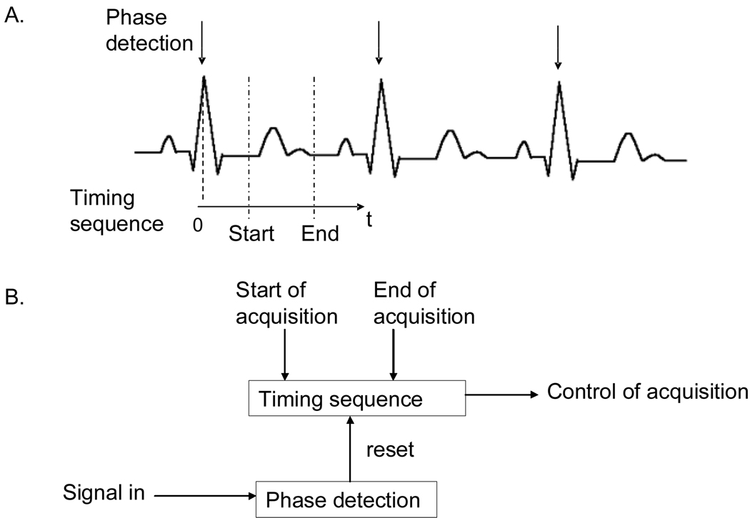
Gating algorithms, in essence, provide an acquisition window, usually a 0 to 5 V TTL signal, with a user-determined width and the timing of which depends upon a periodic signal. The difficult part of creating a gating window is to extract the phase and/or the period of the signal under study. Many approaches are available.8 Among the most widely used are periodic level detection (usually combined with differentiation), digital filters, and pattern recognition. Following that phase extraction, a timing sequence is used to define the acquisition window. The principles of phase detection and timing are illustrated in Figure 1.A with a commonly used signal, the ECG. QRS complex is detected and resets a timing sequence. Their adaption in terms of block diagram schematics is shown in Figure 1.B.
Figure 1. GATING PRINCIPLE.
that consists of a signal phase detection that triggers a timing sequence. A. Illustrates this principle with cardiac gating on the ECG. Phase is detected on the QRS complex and triggers a timing sequence used for acquisition. B. Translates this approach in terms of block diagram schematics.
2.2. Phase detection and pre-processing
Prior to entering the proper signal processing, the signal undergoes four pre-processing filters. Sequential preprocessing performs filtering with high-frequency removal for noise reduction (providing also smoothing of discrete levels if needed), DC level removal for avoiding low-frequency alteration of the signal level, gain correction, and absolute value. The absolute value filtering allows for positive and negative features immunity, if needed. When combined, these filters allow standardization of the signal’s level and allow application of the same processing tools to all periodic signals.
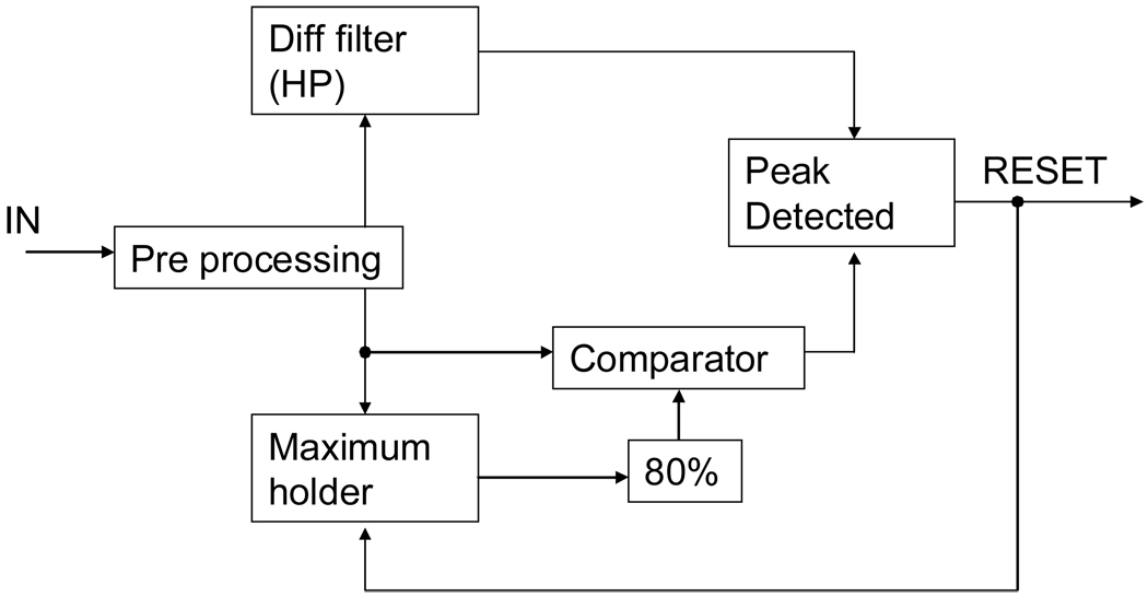
We chose to develop a gating circuit based upon level and differential phase detection. In essence the phase signal is extracted from the differentiator filter and the level detection, not relevant for accurate phase detection, offers a false positive rejection. Both operations are performed in parallel and deliver a 0 to 5V TTL signal for identifying the phase. As shown in Figure 2 the signal undergoes pre-processing and then splits into a derivative section (upper branch) and a level detection section (lower branch).
Figure 2. PHASE DETECTION.
Signal is pre-processed (high frequency noise filtering, DC removal, gain and absolute value) and phase is assessed through both a level detection (lower path) and a differentiator filter (higher path).
The differentiator section is simply a high pass filter. This high pass filter is compensated by a low pass filter at very high frequencies for noise immunity. The derivative of the signal is then compared to a fixed voltage issuing a pulse when the signal derivative reaches the desired threshold value.
The level detection is a bit more complex. In essence, it compares the voltage of the signal to a fixed reference voltage. In practice, due to signal peak variation, one needs to adapt the value of the reference voltage. This is performed by a maximum holder. This maximum holder is reset each time a peak is detected, i.e. each period, and reflects the previous period maximum. This maximum voltage is then lowered to 80% of its value and compared to the real-time incoming signal. This strategy allows for compensating low variations both in time and amplitude of the peak maximum. The output signal is a 0 to 5 V TTL signal indicating when the incoming signal is greater than the reference voltage.
Finally, the two TTL windows are merged together using an AND gate and provide a reliable phase detection for the incoming signal.
2.3. Timing
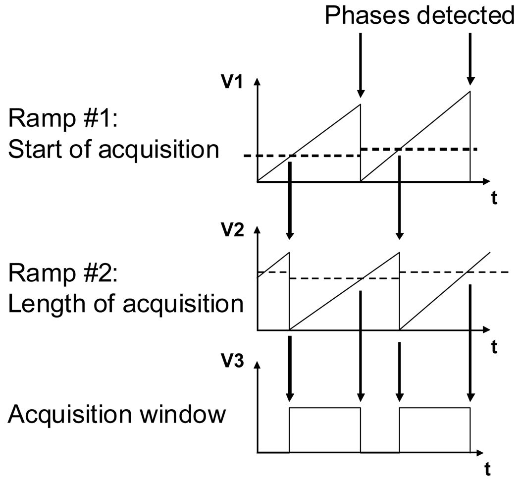
Once the phase reset signal has been generated, creating the acquisition window is a matter of precise timing. Many approaches are possible. One can have a clock and a counter and simply look for the proper time to launch acquisition. The problem with this approach is the discretization of time, especially during long periods, such as the respiratory cycle, which renders the technique impractical for precise timing. We tried both approaches and the preferred approach is the more versatile generation of a time-voltage ramp. Although this technique is more complex to implement, it has the advantage of generating an analog, not descretized, ramp. Additionally, in order to generate an acquisition window that can be placed anywhere on the gated signal, we are using two ramps: one for starting the acquisition and the other for the length of acquisition. As illustrated in Figure 3, the first ramp is reset using the phase detection pulse. This ramp is then compared to a first reference threshold voltage that sets the start of acquisition. When the acquisition starts, the second ramp is reset and compared to a second reference threshold voltage that sets the end of acquisition. The comparison of the latter reference voltage with the latter ramp provides the acquisition timing window.
Figure 3. TIMING.
Two time-voltage ramps are necessary for placing the acquisition window at anytime compare to the incoming signal. Ramp #1 is reset when the phase is detected and compare to a first reference timing. When ramp #1 passes the reference voltage, acquisition is started and ramp # 2 is reset. Finally ramp #2 is compared to a second reference voltage. Put together, these two ramps allow for defining an acquisition window of any length and at any time.
To account for signal period variation, we scaled the reference threshold voltage for timing to the period of the signal. For this purpose we use a sample-and-hold that holds the last value from the first time-voltage ramp at the end of the period (prior to reset). The reference threshold voltages for timing are then expressed as percentage of this value. This strategy allows for compensating slow period variations and thus the circuit to accommodate pseudo-periodic signals. This strategy assumes that the signal features and thus the physical motions are stretching proportionally to the period of the signal. We think this is a reasonable assumption in terms of physiological signals (ECG and respiration).
3. PARTS AND METHODS
2.1. Parts
The electronic circuit Gerber files described in this article and the list of components are available online at www.frangionilab.org. It is composed of simple, easily available, and inexpensive electronic components. The function generator used for the validation and calibration of the circuit is a dual channel Hewlett-Packard (HP) model HP-3245a. The oscilloscope used for visualizing the signals is a LeCroy WaveSurfer 44Xs, 400MHz and up to 2.5 GS/s. The ECG and respiratory signals have been obtained through a Datex/Ohmeda S/5 vital signs monitor. TTL gating window acquisition was performed using a National Instrument PCI-6229 acquisition board. Gated image acquisition has been performed on a single PC using custom-made Labview software that simultaneously acquires two fire-wire cameras (color and near-infrared) and the gating signal. Power is supplied to the board using a +12 V, −12 V, +5 V Elpac WM220-1 power supply.
2.2. Methods
For filtering purposes, the board can be selected to work in two different frequency ranges. We chose 0.1 Hz to 1 Hz for the first range and 1 Hz to 10 Hz for the second range. These two ranges have been chosen to fit both ECG and respiratory ranges from mouse to human. Conveniently, jumpers allow the user to select between these working ranges enabling adaptation of the filters values and time-voltage ramps slopes. Additionally, as for some signals such as the respiratory signal (50% duty cycle), the absolute value is not necessary and can even impair phase detection; a jumper allows to disable this feature.
Outputs of the board are as follows: TTL gating window for current board, cumulative TTL gating window for all the boards up to the current one (if several boards are stacked), end-of-period time-to-voltage ramp value, and filtered incoming signal. The ramp value can be used to deduct the signal’s period if it has been calibrated using an incoming signal of well-known frequency.
Operation is very simple. After choosing the frequency range, the signal inputs to be gated are plugged into the inputs of the boards and power applied. The gating window starts at a random state and is available after the first period of the gated signal. The user can then tune the gating window he needs by use of the digital potentiometer inputs. Outputs can then be used to trigger a task.
2.3. Large animal surgery
Animals were housed in an AAALAC-certified facility staffed by full-time veterinarians and were studied under the supervision of an approved institutional protocol. Yorkshire pigs were of either sex and were purchased at 30 kg from E.M. Parsons and Sons (Hadley, MA). All animals acclimated to the animal facility for at least 48 hours prior to experimentation. Anesthesia was induced using 4.4 mg/kg intramuscular Telazol (Fort Dodge Labs, Fort Dodge, IA) and anesthesia maintained through a 7 mm endotracheal tube with 1.5% isoflurane/98.5% O2 at 5 L/min. The heart was exposed for imaging by a midline sternotomy. After each study, anesthetized pigs were euthanized by rapid intravenous injection of 10 ml of Fatal-Plus (Vortech Pharmaceuticals, Dearborn, MI). This method of euthanasia is consistent with the recommendations of the Panel on Euthanasia of the American Veterinary Medical Association.
ECG acquisition was performed using the 3 leads configuration from the Datex/Ohmeda S/5 vital signs monitor. The pig was shaved on the region where the electrodes (3M Red Dot, model 2560) were placed. We placed one electrode on the lower left limb and two electrodes on each upper limb. Finally we configured the outputs of the vital signs monitor to show the desired signal.
4. RESULTS AND DISCUSSION
4.1. Results
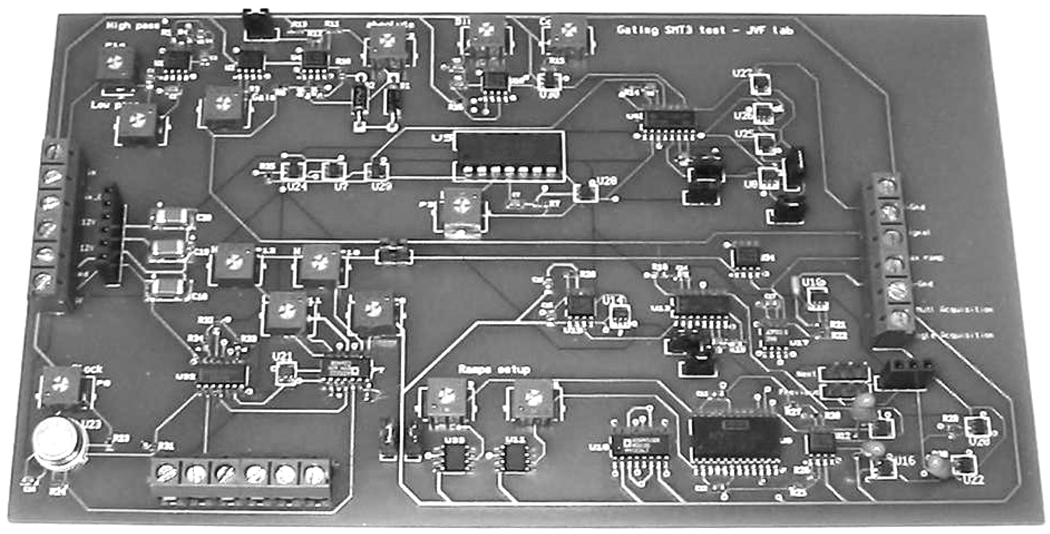
Boards were manufactured at PCBexpress (www.pcbexpress.com) and assembled by Sure Design (Farmingdale, NJ). Final boards are 7” × 4” in size and cost approximately $500 ($50 for components, $150 for board manufacturing, $300 for assembly). A picture of the board is shown in Figure 4. Please note that a miniaturized version of this board is currently in the design phase.
Figure 4. THE GATING BOARD.
Measures 7” × 4” and costs approximately $500 (with assembly). It delivers a TTL gating acquisition window of any length and at any time relative to the incoming signal. It also uses a stackable design that allows simultaneous and cumulative gating of several incoming signals. A miniaturized version of this board is currently designed.
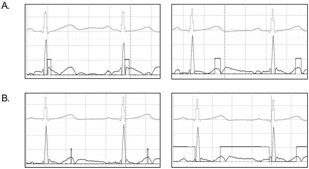
Boards were tested using the dual channel 1 MHz HP function generator. One channel was set to a 0 – 500 mV square wave with 10% cycle at 1 Hz for simulating the ECG signal. The second channel was set to 0 – 500 mV sinewave with 50% duty cycle at 0.05 Hz for simulating low frequency noise. Both channels are sent to a bias-tee (Mini-Circuit, model ZFRSC-42) and the output is sent to the circuit input. Circuit has been validated on the author’s ECG through Datex/Ohmeda S/5 vital signs monitor. As shown in Figure 5 the gating window can be placed anywhere in the gated signal and of any length. The incoming, unfiltered signal is shown on top, the filtered signal and the gating TTL window are shown at the bottom. For clarity, the incoming ECG signal has been shifted up compare to the other signals.
Figure 5. THE ACQUISITION WINDOW.
Obtained from a human ECG. The ECG on top is the raw incoming ECG signal coming out of the Datex/Ohmeda S/5 vital signs monitor. The bottom ECG signal is post-processed (noise filtration, DC-removal and absolute value). Acquisition window is super-imposed to the bottom curve and can be placed at anytime (Figure A.) and of any length (Figure B.)
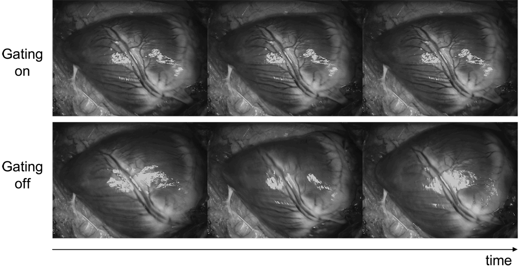
Finally, a board was used to gate an image acquisition using the ECG from a Yorkshire pig as described previously. Figure 6 shows a movie sequence of a gated and a non-gated heart. Notice the randomness of the pictures when non-gated and their similarity when gated.
Figure 6. HEART PICTURES.
sequence from a Yorkshire pig acquired using the gating circuit. The pig’s ECG has been acquired using the Datex/Ohmeda S/5 vital signs monitor and processed by the gating board. The TTL acquisition window has been sent to a PC using a NI PCI-6229 data acquisition board. Finally a custom- made Labview software has been use to acquire the picture gated by the circuit. Note that these images have been taken sequentially during a movie capture.
4.2. Discussion
The circuit provides a reliable and robust TTL acquisition window provided that the incoming signal is pseudo-periodic. Therefore careful attention should be paid to the quality of the incoming gated signal. During in vivo situations in particular, perturbing the gated signal is very common. Spikes in the signal are easily generated and impair the proper functioning of the circuit. Two steps can be taken to avoid this situation. First, one has to limit disturbance of the signal when gating is desired (for instance to avoid touching the ECG lead wires). Second, in software, when the ramp output becomes constant (no phase detected), the circuit should be reset. This could also be implemented in hardware on the board itself if one wishes to improve this circuit.
The software that handles this TTL gating signal is critical. In some cases where the exposure time of the camera is independent from the gating period, particular attention should be paid to the exposure time of the camera versus the gating period. Two situations are generally encountered. In the first case, the gating period is larger than the camera exposure time. This implies that for one gating period there will be several camera acquisition cycles and images displayed at the end of each camera cycle. In the second case, the camera exposure time is larger than the gating period. This implies that one image will be built over multiple gating periods until the required exposure time is obtained. Images should be added up until the end of the exposure time. Depending on the camera hardware, another way to avoid these issues is to be able to trigger the camera acquisition directly from the TTL gating signal. In this case, exposure time could be directly linked to the gating signal avoiding complicate software situations.
5. CONCLUSION
We designed, constructed, and validated a low-cost, universal, and cumulative gating circuit for small and large animal clinical imaging. Based on inexpensive and available electronic components and using a stackable design, this circuit can be used to gate any type and any number of pseudo-periodic signals. The gating window width and position can be controlled either directly by the user or using a PC thanks to digitally controlled potentiometers. Additionally, the circuit automatically adapts to low magnitude and slow variations of incoming signal period and amplitude.
In summary, this circuit allows gating of in vivo image acquisition to physiological signals, potentially greatly improving the quality of the acquired images and surgical procedure.
ACKNOWLEDGMENTS
From the Boston University Department of Biomedical Engineering, we thank Jerome Mertz for assistance with the gating algorithm. From the Beth Israel Deaconess Medical Center, we thank Aya Matsui and Rita Laurence for the animal surgeries. We thank also Barbara L. Clough for editing, Eugenia Trabbuchi and Alice Gugelmann for administrative assistance. This work was supported by NIH grant #R01-CA-115296 to Dr. Frangioni.
REFERENCES
- 1.Sevick-Muraca EM, Houston JP, Gurfinkel M. Fluorescence-enhanced, near infrared diagnostic imaging with contrast agents. Curr Opin Chem Biol. 2002;6:642–650. doi: 10.1016/s1367-5931(02)00356-3. [DOI] [PubMed] [Google Scholar]
- 2.Ntziachristos V, Bremer C, Weissleder R. Fluorescence imaging with near-infrared light: new technological advances that enable in vivo molecular imaging. Eur Radiol. 2003;13:195–208. doi: 10.1007/s00330-002-1524-x. [DOI] [PubMed] [Google Scholar]
- 3.Soltesz EG, Laurence RG, De Grand AM, Cohn LH, Mihaljevic T, Frangioni JV. Image-guided quantification of cardioplegia delivery during cardiac surgery. Heart Surg Forum. 2007;10:E381–E386. doi: 10.1532/HSF98.20071099. [DOI] [PMC free article] [PubMed] [Google Scholar]
- 4.Tanaka E, Ohnishi S, Laurence RG, Choi HS, Humblet V, Frangioni JV. Real-time intraoperative ureteral guidance using invisible near-infrared fluorescence. J Urol. 2007;178:2197–2202. doi: 10.1016/j.juro.2007.06.049. [DOI] [PMC free article] [PubMed] [Google Scholar]
- 5.Cuccia DJ, Bevilacqua F, Durkin AJ, Tromberg BJ. Modulated imaging: quantitative analysis and tomography of turbid media in the spatial-frequency domain. Opt Lett. 2005;30:1354–1356. doi: 10.1364/ol.30.001354. [DOI] [PubMed] [Google Scholar]
- 6.Cuccia DJ, Bevilacqua F, Durkin AJ, Ayers F, Tromberg BJ. Quantitative mapping of turbid media optical properties using modulated imaging. J Biomed Opt. 2006 doi: 10.1117/1.3088140. In Press. [DOI] [PMC free article] [PubMed] [Google Scholar]
- 7.Gioux S, De Grand AM, Lee DS, Yazdanfar S, Frangioni JV. Improved optical subsystems for intraoperative near-infrared fluorescence imaging. Proc. SPIE 6009. 2005 60090C1-10. [Google Scholar]
- 8.Kohler B-U, Henning C, Orglmeister R. The principles of software QRS detection. IEEE engineering in medecine and biology. 2002;21:42–57. doi: 10.1109/51.993193. [DOI] [PubMed] [Google Scholar]


