Abstract
Speckle noise significantly limits the information content provided by coherent optical imaging methods such as optical coherence tomography and its recent derivative, optical frequency-domain imaging (OFDI). In this paper, we demonstrate a novel OFDI system that simultaneously acquires hundreds of angularly resolved images, which can be compounded to reduce speckle noise. The system comprises an InGaAs line-scan camera and an interferometer, configured so that the elements of the detector array simultaneously capture light spanning a backscattering angular range of 32 degrees. On successive read-outs of the array, the wavelength of the laser source was stepped through a range of 130 nm centered at 1295 nm to concurrently generate 400 angle-resolved OFDI images. A theory of angle-resolved OFDI and the design equations of the system are presented. Incoherent averaging of the angle-resolved data is shown to yield substantial speckle reduction (as high as an 8 dB SNR improvement) in images of a tissue phantom and esophageal tissue ex vivo.
1. Introduction
Recent advances in optical frequency domain imaging (OFDI) have yielded systems capable of minimally-invasive cross-sectional imaging of biological tissue with both high frame-rates and high sensitivity [1-3]. As such, OFDI has significant potential as a tool for identifying morphological changes in many clinical contexts, including cardiovascular, gastrointestinal, and retinal imaging. As in optical coherence tomography (OCT), OFDI images are significantly confounded by speckle, which manifests as a grainy pattern within scattering regions. Speckle greatly reduces contrast between regions with small, intrinsic reflectance differences and limits the effective spatial resolution of spectroscopic and polarization-based measurements. Given that subtle changes in the scattering properties of tissue have been associated with transitions from normal to diseased states, speckle reduction may be critical in order for OFDI to realize its full clinical potential.
Many different methods have been proposed for mitigating the effects of speckle, including median filtering, phase-domain processing [4], frequency compounding [5], wavelet-based filtering [6], and I-divergence regularization [7]. While these methods have met with some success, most suffer the drawback of a loss of spatial resolution. The method of angular compounding, in which separate images acquired from different backscattering angles are averaged incoherently, does not necessarily involve that compromise. Schmitt [8] demonstrated speckle reduction by angularly compounding four images acquired simultaneously with a quadrant photodiode detection system. Similarly, Bashkansky and Reintjes [9] averaged ten images acquired sequentially, using a free-space OCT system in which the angle of the incident beam with respect to the tissue normal was varied by translation of a prism. The method of Iftimia et al. [10], which is compatible with fiber based systems, encoded three backscattering angles simultaneously by path length. Angularly compounded images from these studies still show high levels of speckle, however, which reflects the small number of detected angles employed.
We present a novel OFDI system in which array detection is employed for massively-parallel angular acquisition. The system can simultaneously acquire 100-fold more angles than previous approaches. Using the method of angular compounding, we demonstrate high levels of speckle reduction without a substantial decrease in spatial resolution.
2. Principle of angular compounding for speckle reduction
Speckle results from distortions of the backscattered wavefront that are caused by low-angle multiple forward scattering and multiple backscattering from closely separated refractive index heterogeneities [11]. Angular compounding methods take advantage of the statistical decorrelation between light back-reflected through different angles. By averaging signals from different scattering angles incoherently, a signal with lower variation relative to the mean is obtained, which translates in imaging terms to speckle reduction.
OCT and OFDI systems measure the complex reflectivity, S (z) , as a function of depth. Images are generated by displaying the magnitude of the reflectivity, I (z) = S (z) S* (z). Following previous studies [8], we define the measured signal-to-noise ratio (SNR) as the ratio of the mean power reflectance, ⟨I⟩, to the standard deviation of the power reflectance, σI, within a homogeneous scattering region:
| (1) |
Detection of backscattered light at different angles provides multiple measurements of reflectivity at the same spatial location. In angularly compounded OCT, the reflectivity at a given point is calculated as the incoherent average of all measured reflectivities. It is expected that the SNR of the compounded signal increases proportionally to the square-root of the number of statistically uncorrelated averages.
3. Imaging system
3.1 Interferometer
The angle-resolved OFDI system comprised an interferometer in which single-mode laser light was injected into two arms from an optical fiber coupler (Fig. 1). Collimated light from the first arm was directed through the beam splitter and focused onto the sample; back-reflected light interfered with a spatially expanded reference beam from the second arm at the beam splitter and was incident on a detector array. As the wavelength of the light source was stepped, exposures of the array were acquired, with the path lengths of the reference and sample arms held constant. In this way, the depth dependence of the reflectance was encoded in the frequency domain. The scattering angle of the detected backscattered light with respect to the incident beam was encoded in the spatial domain, as the distribution of light intensities across the detector array. An axial reflectivity profile corresponding to a narrow backscattering angular range was obtained for each detector from the signal generated by successive wavelength scans. The axial reflectivity profile is the Fourier conjugate of the detected signal, and can be recovered with the Discrete Fourier Transform (DFT) [1].
Fig. 1.
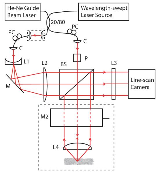
Angle-resolved OFDI system. C: collimator; L1, L2, L3: cylindrical lenses; L4: aspheric doublet lens; PC: polarization controller; BS: beam splitter: P: polarizer; M1: stationary mirror; M2: galvanometer mirror. The gray-dashed region is oriented perpendicular to the plane of the interferometer.
Light in both arms of the interferometer was initially collimated (2.4 mm 1/e2 diameter). Subsequently, the light beam directed at the sample was linearly polarized by a Glan-Thompson polarizer. This polarizer facilitated alignment but was not a necessary component of the system. The reference beam was expanded horizontally to an ellipsoidal beam using a cylindrical lens telescope with magnification ratio of 62.5 (f1 = -6.4 mm; f2 = 400 mm). The large magnification ratio ensured that the reference beam power varied by less than 5 percent across the detector array. A free-space coupler allowed control over the reference beam power as well as the relative difference in path length between the two arms. A cylindrical lens (f3 = 76 mm) focused the output of the interferometer onto the pixel array of the linescan camera. Light received from the imaging sample was incident on 400 pixels of the array. An additional 20 pixels from one side of the detector array collected reference arm light only, for relative intensity noise (RIN) subtraction.
Sample arm light was focused onto the sample by an aspheric doublet lens with a diameter of 25 mm and a focal length of 35 mm. The focused spot size was 24.1 μm (1/e2 diameter), with a confocal parameter of 704 μm. Scanning of the sample arm light across the sample was performed by a galvanometer (Model 6800, Cambridge Technology) placed one focal length above the focusing lens, with its axis of rotation within the plane of the interferometer. The galvanometer was driven by computer such that 1000 A-lines were collected per two-dimensional image. Light from a He-Ne laser was injected into the fiber coupler and served as a guide beam during imaging.
The optical source was an extended-cavity semiconductor wavelength-swept laser employing a semiconductor optical amplifier (Covega) and intra-cavity filter. A schematic of the source is given in Fig. 2. The resonator design was similar to that previously used for high-speed OFDI [12] with the exception that a galvanometer scanner was used rather than a polygon scanner for wavelength tuning. The laser generated polarized light with an output power of 30 mW averaged across the 130 nm tuning range, which was centered at 1295 nm The wavelength sweep rate (A-line rate) was 25 Hz, limited by the 750 frequency samples per A-line required to achieve adequate ranging depth and the CCD array readout rate (∼19 kHz).
Fig. 2.
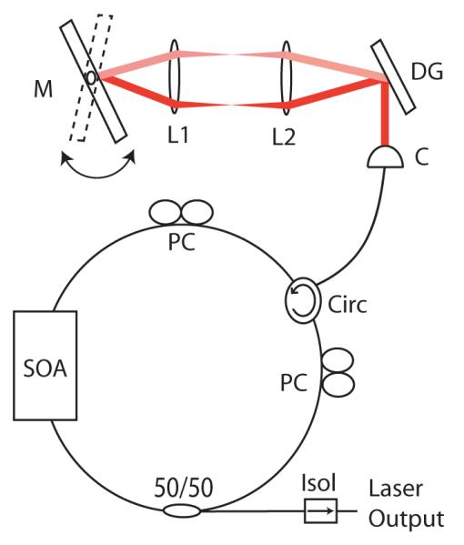
Frequency-swept source. SOA: semiconductor optical amplifier; Circ: circulator: PC: polarization controller; C: collimator; L1, L2: aspheric doublet lenses; DG: diffraction grating; M: galvanometer mirror; Isol: isolator.
The InGaAs line-scan camera (SU512 LX, Sensors Unlimited) had 512 pixels, with a detector pitch of 50 μm and height of 500 μm. The full-well depth was 5×10⁶ electrons. Exposures were 24 μs in duration, with a duty cycle of 46%. Analog output, interleaved among 4 channels, was digitized at 12 bits by a digital acquisition (DAQ) card operating at 5 MS/s per channel (PCI-6115, National Instruments). The drive signal provided to the galvanometer in the wavelength-swept laser was synchronized to the trigger signal generated by the camera. For images comprising 1000 A-lines, the acquisition time was 40 s.
3.2 Image reconstruction
Data processing for a particular A-line corresponding to a single angular sample included five steps: a) background subtraction; b) RIN subtraction; c) interpolation and mapping from wavelength- to k-space [1]; d) multiplication with a Hanning window to correct non-uniformities in the integrated optical spectrum; e) DFT. For step b), RIN noise was estimated by subtracting the values obtained at the RIN subtraction pixels from their average values, with averaging performed separately for each wavelength step. The estimated RIN noise was subsequently subtracted from interference signals obtained from other pixels. Averaging of angular images was performed after computing the absolute value of the DFT. Angles that were evenly spaced across the full angular collection range were used for averaging in order to minimize correlations between corresponding signals; for instance, in the case of averaging across only three angular samples, backscattering angles of -16, 0, and 16 degrees are chosen. No spatial filtering operations were performed on images before or after angular averaging. Reflectivities were mapped to a log grayscale to generate 2D images.
3.3 Angular and spatial resolution
Assuming that all angles transmitted by the lens are collected by the detector array, and that the incident beam is normal to the imaging sample surface, the signal from the ith detector derives from an angular sampling interval centered at an angle θi of:
| (2) |
where M is the number of detectors and NA is the numerical aperture of the lens. It follows that the width of the angular response of the system is bounded by 2sin-1 (NA)/M . For our system, backscattered light within an angular range of 32° was detected by 400 pixels.
The transverse resolution, δzT, is determined by the system optics. In particular, it is determined by two factors: the transverse width of the focused sample beam, and the transverse width of the region in which light is collected by individual detector array elements. Whilst the two widths are identical in a conventional OFDI system, the latter is broader than the first in the angle-resolved system since the dimensions of individual array elements are smaller than those of the incident beam. As a result, the in-plane transverse resolution is slightly degraded compared with that of a conventional OFDI system employing the same sample arm optics. This degradation of the in-plane transverse resolution does not apply to the out-of-plane transverse resolution, since a cylindrical lens in front of the detector array (L3) ensures that out-of-plane light from a broad angular range is collected. With the approximation that the laser spectrum is Gaussian, the axial resolution of the system, δzA, is that of a conventional OFDI system: δzA = 2ln 2λ02/(πnΔλ), where λ0 is the center wavelength, Δλ is the full-width-at-half-maximum (FWHM) of the spectral envelope, and n is the group refractive index of the sample. The ranging depth, Δz , is given by Δz = λ02/(4nδλ) , where δλ = Δλ/Ns is the sampling wavelength interval and Ns is the number of samples within FWHM range of the spectrum, Δλ [1]. For our system, the axial resolution was 8.0 μm in air, and the total ranging depth was 2.5 mm in air.
3.4 Sensitivity
The interference signal, , received in the Fourier domain by the ith detector as a function of the frequency of laser light ν, is:
| (3) |
where η is the quantum efficiency of the detector and G is its gain, τ is the exposure time, and P(ν) is the total power at the entrance of the interferometer. R(z) and φ(z) are the amplitude and phase terms of the reflectance profile, respectively. The axial distance z is expressed as a relative distance, with z = 0 corresponding to zero optical path difference between the reference and sample beams. The power of the reference beam that reaches detector i, expressed as a fraction of the source power, is denoted as γr,i. The corresponding fractional power from the sample, in the case of R = 1 , is denoted as γs,i. We assume that the laser line-width is narrower than the wavelength sampling interval. It follows that in the shot noise limit, the sensitivity Σi corresponding to detector i is given by [13]:
| (4) |
where P0 is the total integrated power and ν0 is the center frequency of the laser source. By imaging a mirror in the presence of an attenuator, a maximum sensitivity of 106.5 dB was measured for a single angular sample (180° back-reflection) corresponding to back-scattering. By comparison, the theoretical maximum sensitivity of the system was 132 dB [Eq. (4)]. The sensitivity decreased to 101 dB at 90 percent of the ranging depth. The difference between the shot noise limited and the measured SNR can be attributed in part to the effects of detector noise and incomplete RIN cancellation. Of these, the former effect was observed to be dominant. The difference can also be attributed to incomplete modal overlap between reference and sample beams.
4. Imaging
4.1 Phantom
A two-layer tissue phantom was constructed from aqueous agar gel (0.5% agar by weight) and polymer microspheres of diameter 0.3 μm (Duke Scientific). An initial scattering layer with an approximate depth of 2 mm was formed in a silicone isolator (Sigma). An overlying scattering layer, designed to have a lower scattering coefficient, was formed on top of the first and had an approximate depth of 450 μm. By analysis of the exponential signal attenuation with respect to depth, the scattering coefficients (μs) were estimated to be 24 cm-1 and 12 cm-1 for the lower and upper layers, respectively. Imaging of the phantom was performed using the system described above and each angular channel was archived digitally.
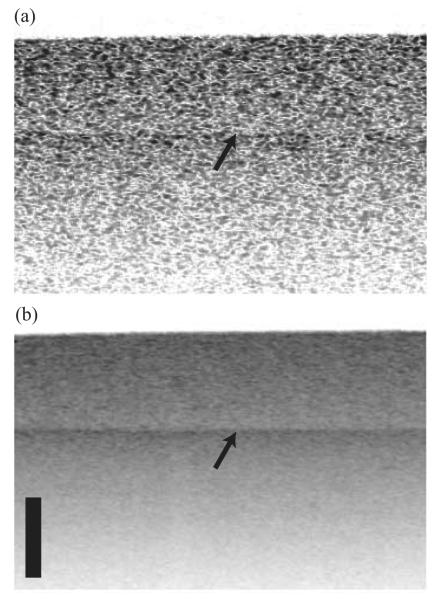
Images acquired with a single angular sample (180° back-reflection) exhibited high levels of speckle and the boundary between the two layers was difficult to discern [Fig. 3(a)]. Upon incoherent compounding of the 400 angular channels, however, the boundary between the two layers was clearly visible [Fig. 3(b)].
Fig. 3.
Images of a two-layer tissue phantom obtained from 1 angular sample (180° backreflection) (a) and from compounding 400 angular samples (b). The arrow points to the boundary between the two layers. Top layer μs = 12 cm-1; bottom layer μs = 24 cm-1. The scale bar corresponds to 500 μm in depth; the transverse extension of the images is 4 mm.
The extent to which the SNR is increased by angular compounding is dependent on the level of correlation between angular samples. In general, we can expect lower levels of correlation for samples containing large numbers of scatterers. In comparison, sharp interfaces and scatterers with dimensions similar or larger to the size-scale of the resolution are likely to show little or no change with angular compounding. A useful measure of angular correlation can be found in the normalized autocorrelation function, C:
| (5) |
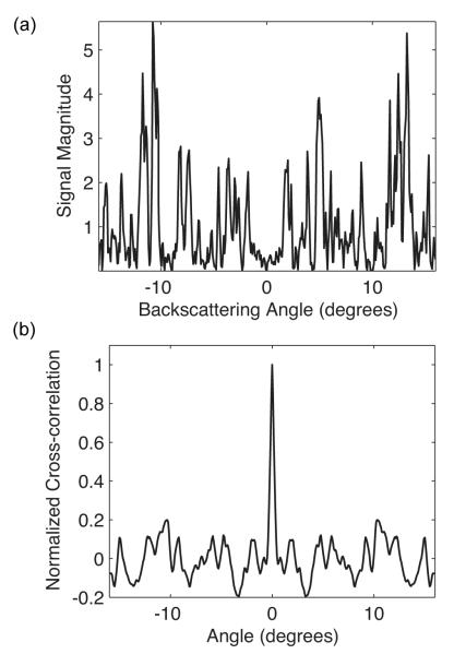
where the signal subscript corresponds to an angular sample index. In particular, the width of the central lobe of the autocorrelation function is indicative of the extent of the correlation between successive angular samples. Taking the width to be the angular distance for which C > 1/e2 (relative to a maximum of unity), values of 1.1 ± 0.4 degrees were observed for resolution elements 500 μm from the surface of the tissue phantom. A representative angular distribution obtained from 500 μm and the corresponding cross-correlation function are shown in Fig. 4.
Fig. 4.
Angular distribution obtained from one resolution element within the tissue phantom (a) with corresponding normalized cross-correlation function (b).
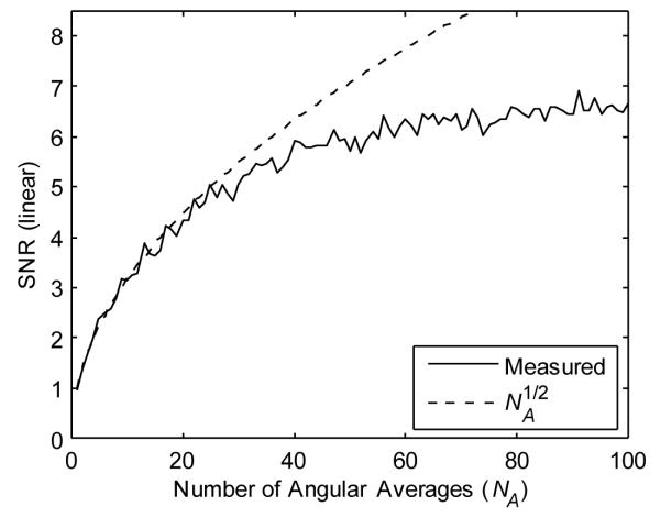
The optical homogeneity of the tissue phantom within each scattering layer is conducive to SNR measurements. For signals acquired from a depth of 500 μm, the SNR [as defined in Eq. (1)] was 0.95 for an image obtained from a single angular sample. This is consistent with the theoretical prediction of unity for the case of fully-developed speckle and imaging with a single polarization state [11]. The SNR increased in direct proportion to the square root of the number of angular samples, NA, for angular averaging performed with approximately 30 or fewer angles that were evenly spaced across the total collection range. SNR improvement deviated from the NA1/2 relationship for averaging in which angular samples were more finely spaced, ultimately reaching a maximum of 6.5 (Fig. 5). This suggests that angular samples were correlated over a distance of approximately 0.8 degrees, a result consistent with measured cross-correlation widths.
Fig. 5.
SNR as a function of the number of angular averages, NA, for signals acquired from a depth of 500 μm within the tissue phantom.
4.2 Porcine esophageal tissue
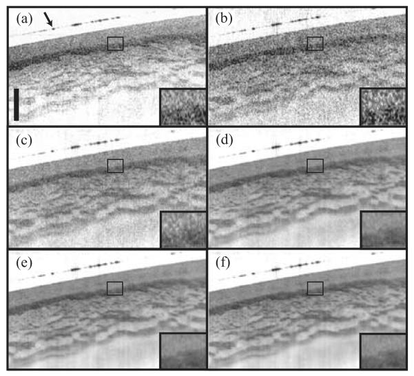
The effects of angular compounding were striking when applied to porcine esophageal tissue ex vivo (Fig. 6). Porcine esophageal samples were mounted with a coverslip to retain moisture and minimize specular reflection from the surface. Qualitatively, the image generated from a single angular sample [Fig. 6(b)] was very similar to that obtained from a state-of-the-art conventional OFDI system [14] employing the sample arm optics of the angle-resolved system [Fig. 6(a)], both in terms of the features that are resolved and the speckle noise. Only one polarization channel of the conventional OFDI system was employed to facilitate comparison between the two images. With 4 compounded angles [Fig. 6(c)], the level of speckle reduction is such that the layers and structure can be resolved only in certain parts of the image. With 16 or more angular averages [Fig. 6(d)-(f)], the layers and structure are clearly resolved across the length of the image. It is interesting to note that the differences in speckle reduction resulting from increasing the width of the angular averaging window was most striking for widths of 16 or less; little improvement was observed for larger windows. These angle-compounded images of esophageal tissue highlight how subtle reflectance differences within tissue can be obscured by speckle, and recovered by angular compounding. Importantly, angular compounding does not appear to substantially degrade spatial resolution. A more detailed study of the impact of angular compounding on spatial resolution will be described in a future work.
Fig. 6.
Images of porcine esophageal tissue obtained from a conventional OFDI system (a) and from the angle-resolved OFDI system by compounding 1 (b), 4 (c), 16 (d), 64 (e), and 256 (e) angular samples. The scale bar corresponds to 500 μm in depth; the transverse extension of the images is 6 mm. The arrow points to the top surface of the coverslip overlying the tissue.
5. Conclusion
Angular diversity is a powerful method of speckle reduction and has hitherto been limited to averaging across a small number of angles. We have demonstrated an angle-resolved OFDI system with 400 detectors capable of acquiring two-dimensional images from backscattering angles within a range of 32 degrees. Images of tissue phantoms and human tissue obtained from incoherent angular averaging showed high levels of speckle reduction, yielding 8 dB improvements in the signal to noise without a substantial decrease in spatial resolution. While the imaging speed of our prototype system was slow relative to current OFDI technology, the apparatus allows the investigation of angular compounding and will be used to define design specifications for higher-speed systems for speckle reduction.
Acknowledgments
This research was supported in part by the National Institutes of Health, contract R01 CA103769, and by the Terumo Corporation.
Footnotes
OCIS codes: (170.4500) Optical coherence tomography; (170.3880) Medical and biological Imaging; (120.3890) Medical optics instrumentation.
References and links
- 1.Yun SH, Tearney GJ, de Boer JF, Iftimia N, Bouma BE. “High-speed optical frequency-domain imaging,”. Opt. Express. 2003;11:2953–2963. doi: 10.1364/oe.11.002953. [DOI] [PMC free article] [PubMed] [Google Scholar]
- 2.Huber R, Wojtkowski M, Fujimoto JG, Jiang JY, Cable AE. “Three-dimensional and C-mode OCT imaging with a compact, frequency swept laser source at 1300 nm,”. Opt. Express. 2005;13:10523–10538. doi: 10.1364/opex.13.010523. [DOI] [PubMed] [Google Scholar]
- 3.Choma MA, Hsu K, Izatt JA. “Swept source optical coherence tomography using an all-fiber 1300-nm ring laser source,”. J. Biomed. Opt. 2005;10:044009. doi: 10.1117/1.1961474. [DOI] [PubMed] [Google Scholar]
- 4.Yung KM, Lee SL, Schmitt JM. “Phase-domain processing of optical coherence tomography images,”. J. Biomed. Opt. 1999;4:125–136. doi: 10.1117/1.429942. [DOI] [PubMed] [Google Scholar]
- 5.Pircher M, Gotzinger E, Leitgeb R, Fercher AF, Hitzenberger CK. “Speckle reduction in optical coherence tomography by frequency compounding,”. J. Biomed. Opt. 2003;8:565–569. doi: 10.1117/1.1578087. [DOI] [PubMed] [Google Scholar]
- 6.Adler DC, Ko TH, Fujimoto JG. “Speckle reduction in optical coherence tomography images by use of a spatially adaptive wavelet filter,”. Opt. Lett. 2004;29:2878–2880. doi: 10.1364/ol.29.002878. [DOI] [PubMed] [Google Scholar]
- 7.Marks DL, Ralston TS, Boppart SA. “Speckle reduction by I-divergence regularization in optical coherence tomography,”. J. Opt. Soc. Am. A. 2005;22:2366–2371. doi: 10.1364/josaa.22.002366. [DOI] [PubMed] [Google Scholar]
- 8.Schmitt JM. “Array detection for speckle reduction in optical coherence microscopy,”. Phys. Med. Biol. 1997;42:1427–1439. doi: 10.1088/0031-9155/42/7/015. [DOI] [PubMed] [Google Scholar]
- 9.Bashkansky M, Reintjes J. “Statistics and reduction of speckle in optical coherence tomography,”. Opt. Lett. 2000;25:545–547. doi: 10.1364/ol.25.000545. [DOI] [PubMed] [Google Scholar]
- 10.Iftimia N, Bouma BE, Tearney GJ. “Speckle reduction in optical coherence tomography by “path length encoded” angular compounding,”. J. Biomed. Opt. 2003;8:260–263. doi: 10.1117/1.1559060. [DOI] [PubMed] [Google Scholar]
- 11.Schmitt JM, Xiang SH, Yung KM. “Speckle in optical coherence tomography,”. J. Biomed. Opt. 1999;4:95–105. doi: 10.1117/1.429925. [DOI] [PubMed] [Google Scholar]
- 12.Yun SH, Boudoux C, Tearney GJ, Bouma BE. “High-speed wavelength-swept semiconductor laser with a polygon-scanner-based wavelength filter,”. Opt. Lett. 2003;28:1981–1983. doi: 10.1364/ol.28.001981. [DOI] [PubMed] [Google Scholar]
- 13.Leitgeb RA, Hitzenberger CK, Fercher AF. “Performance of fourier domain vs. time domain optical coherence tomography,”. Opt. Express. 2003;11:889–894. doi: 10.1364/oe.11.000889. [DOI] [PubMed] [Google Scholar]
- 14.Vakoc B, Yun S, de Boer J, Tearney G, Bouma B. “Phase-resolved optical frequency domain imaging,”. Opt. Express. 2005;13:5483–5493. doi: 10.1364/opex.13.005483. [DOI] [PMC free article] [PubMed] [Google Scholar]


