Abstract
Electrical Impedance Myography (EIM) is a non-invasive, painless clinical technique for the diagnosis and monitoring of a variety of neuromuscular diseases including amyotrophic lateral sclerosis and focal nerve injuries. It involves the application of a low-intensity alternating current to a muscle group and the measurement of the consequent surface voltage patterns. This paper presents a system for the rapid and accurate acquisition of data employing an interrogating signal composed of multiple tones with frequencies between 10 kHz and 4 MHz. The use of this composite signal makes possible measurement of impedance at multiple frequencies simultaneously. In addition, this system takes impedance measurements at multiple orientations with respect to the muscle fibers by means of an electronically reconfigurable electrode array and utilizes the linearity of muscle tissue to reduce the required measurement time. Testing of the EIM system on beef has established the capability of this system to rapidly detect the anisotropic conductive properties of muscle tissue at multiple frequencies.
I. Introduction
Bioelectrical impedance has long been considered as a simple, fast, and non-invasive technique for analyzing physiological properties of human tissue [1]. Its basic form involves the application of high-frequency, low-intensity electrical current via surface electrodes attached to the skin. The resultant voltage signal is measured using a second set of electrodes (so-called tetrapolar measurements). The relative amplitude and phase of the measured voltage and the applied current enables the measurement of the resistance and reactance of tissue.
A common application of bioelectrical impedance is in commercial body mass index systems, such as the Imp SFB7 system from ImpediMed, Inc. that computes the fat-to-muscle ratio of a person based on impedance measurements. Other applications include electrical impedance tomography which uses an array of impedance measurements to create anatomical images of human body [2], [3].
A key problem in bioelectrical impedance measurements is the conversion from the measurable electrical parameters to relevant physiological parameters in a manner that is robust across different individuals. It is common, for example, to create equivalent circuit models of a body part, combining capacitors, resistors, and/or inductors in a network that results in a similar impedance profile. However, since most body parts are complex composites of bone, muscle, fat, blood, nerve, and skin, lumped-element circuit models tend to be simplistic, with no straightforward mapping between individual circuit elements and physiological parameters. The issue is further complicated by variations due to age, sex, physical conditioning, hydration level, and genetic makeup [1], [4].
In a series of papers, Rutkove, Shiffman, Aaron, and colleagues have described a relatively robust approach for addressing the aforementioned problem by using localized electrical impedance measurements of muscle, simply referred to as, electrical impedance myography (EIM) [5]–[8]. This technique is developed around the idea that electrical current flows preferentially through the low-resistance, high-volume muscle tissue as compared to other tissues. Data from measurements on human subjects provide convincing evidence of sensitivity to muscle health and fitness, as well as to disease status and progression. A further development of this technique utilizes the fact that muscle conducts electrical current preferentially along the direction of its fibers rather than across its fibers. The measurement of angular anisotropy in muscle is not only able to improve the reproducibility of the EIM technique, but there is also evidence that changes in the anisotropy itself may assist in assessing muscle health and in disease diagnosis [6], [9]–[15].
Prior to this work, experimental clinical application of EIM technique required the careful placement of discrete adhesive strip electrodes on muscles of patients. This procedure was tedious, time-consuming and made obtaining reproducible results difficult. Furthermore, since the electrodes had to be placed by hand, both spatial and directional resolution was limited. In order to enable the clinical application of EIM, an integrated measurement device is required. This paper presents the design and development of a compact, handheld EIM probe and its initial verification on phantom tissues. Specifically, we aim to create a device to simplify the study of the angular anisotropy of human muscle tissue, and thus enable the development of new assessment and treatment strategies for neuromuscular disease.
II. Hardware Develeopment
A. Overview of EIM Measurement System
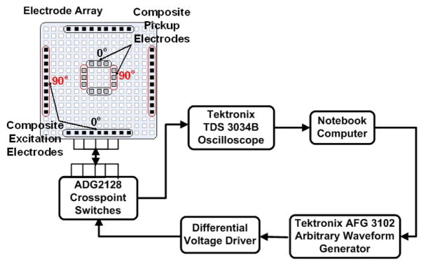
The EIM measurement system, as shown in Figure 1, is composed of a signal generator, a reconfigurable electrode array, a crosspoint switch network, and a data acquisition module. The excitation signal is a composite of multiple tones with logarithmically spaced frequencies from 10kHz to 4MHz. The waveform for this signal is first synthesized using Matlab and then downloaded to a Tektronix AFG3102 arbitrary waveform generator (AWG). A differential voltage driver converts the single-ended signal output from the AWG to a differential signal and also ensures that its amplitude is safe for clinical use. The excitation signal is applied to a patient’s skin via an electrode array fabricated on a printed circuit board. Both the size and position of the excitation and pickup electrodes can be reconfigured on-the-fly using a crosspoint switch network. Electrical impedance measurement as a function of angle and frequency can be accomplished using this arrangement. A Tektronix TDS 3034B oscilloscope sampling at 10MS/s was used as the analog to digital converter needed to digitize the measured voltages for further processing on a portable computer. Mechanically, the EIM system is designed to fit in the hand of a clinician so that impedance measurements of a patient’s muscles can be conveniently made at a variety of positions.
Fig. 1.
Concept diagram of EIM measurement system. Electrode array shown as a rectangular array.
B. Reconfigurable Electrode Head
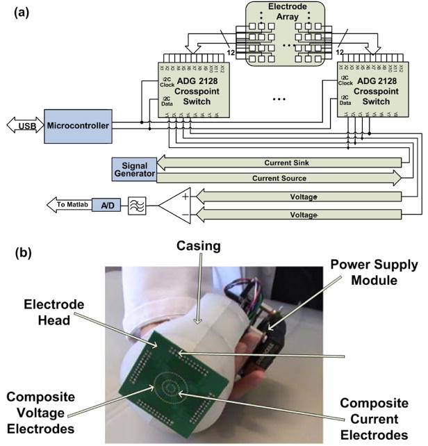
The design of the electrode head is based on an electrode array concept in which neighboring electrode elements are connected together to create a “composite electrode” (see Figure 1). Thus, they act as a single unit which can be used for signal excitation or pickup. Small vias on a printed circuit board act as electrodes for the EIM system. As shown in Figure 2(b) the electrode elements are distributed in three concentric rings. The excitation electrodes are selected from the outer ring, while the pickup electrodes are selected from the two inner rings. Electrode selection is accomplished using several ADG2128 (Analog Devices) crosspoint switches. These devices enable any combination of electrodes to be connected to both the excitation outputs and the detection inputs.
Fig. 2.
(a) System diagram of reconfigurable electrode head. (b) Assembled reconfigurable electrode head with the rectangular electrode grid concept depicted in Figure 1 replaced by an array consisting of concentric rings of individual electrode elements.
Reproducible results can be obtained because the orientation of these composite electrodes with respect to the muscle fibers can be altered without physical movement of the electrode head. This makes it possible to accurately alter the direction of current propagation and improve the angular resolution of measurements. The crosspoint switches are controlled by a portable computer via a USB interface and custom designed software. A system diagram and photograph of the complete and assembled system can be seen in Figure 2.
C. Circuit Design: Differential Voltage Driver
A differential voltage driver was used to amplify the signal to a voltage level suitable for application to the sample. This topology was selected because it is more difficult to design a current source that can operate reliably at higher frequencies. Current sources suffer from the difficulty of maintaining high output impedance at high frequencies due to stray capacitances.
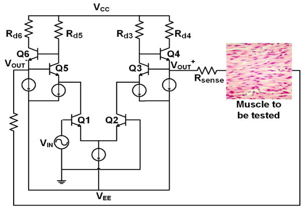
The voltage driver shown in Figure 3 performs several functions. It converts the single-ended signal from the arbitrary waveform generator to a differential signal which will be used in the interrogation of the sample. It also controls the amount of current delivered into the muscle tissue to ensure that it remains within patient safety limits. The input stage consists of an emitter coupled transistor pair (Q1, Q2) which converts the single ended input signal to a differential signal. The signal then passes through the output stage which consists of two transistors in feedback with the base of Q3 connected to the emitter of Q4 and the base of Q4 connected to the collector of Q3. The gain around the feedback loop is approximately unity but the impedance looking into the emitter of Q4 is quite small and given by:
| (1) |
Fig. 3.
Differential Voltage Driver.
Where gm3 and gm4 are the transconductances of Q3 and Q4 and ro3 is the output resistance of Q3. The small impedance at the emitter of Q4 makes this transistor pair a suitable output stage for the voltage driver circuit. It will ensure that very little potential is dropped across the output resistance of the voltage driver so that most of the potential can be dropped across the test sample. Differential signals are used to interrogate the muscle tissue to reduce common mode interference. This increases the reliability of the impedance measurements taken with the EIM system.
III. Signal Processing
A composite signal containing a number of sinusoids with logarithmically spaced frequencies was used as the interrogating signal. By this means, impedance of the muscle group under investigation can be measured at multiple frequencies simultaneously. The fact that muscle tissue acts as a linear medium with respect to current propagation makes this approach possible. Linearity ensures the veracity of measured data because no intermodulation products capable of data corruption are produced. As a result, the speed of measurement is significantly increased over the first generation EIM system in [6] which takes impedance measurements sequentially. The improvement in measurement speed is estimated to be proportional to the number of frequencies at which impedance measurements are taken. Thus, for an experiment investigating 10 frequencies, we expect a measurement speedup factor of about 10.
The key parameter used thus far in monitoring the progress of neuromuscular disease is the change in the phase of the measured impedance over time. Phase is given by,
| (2) |
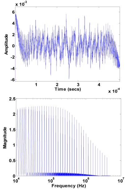
where X is the reactance and R is the resistance. We obtain this information by taking the Fourier transform of the measured and digitized voltages and performing all required numerical computation in the frequency domain. The current flowing through the muscle is obtained by measuring the voltage across the sense resistors, Rsense in Figure 3. The impedance of the muscle is then computed by taking the ratio of the voltage to the current at each frequency. It is important to note that this ratio is taken in the frequency domain rather than in the time domain to preserve the phase information. Figure 4 shows the time domain and frequency domain (Fourier transform) representation of a composite signal composed of 40 sinusoids with logarithmically spaced frequencies. The amplitude roll off exemplified in the frequency plot shows the low pass transfer function of the voltage driver circuit.
Fig. 4.
Time and frequency domain plots of the input signal containing a number of tones at logarithmically spaced frequencies.
Spectral leakage of numerical values into adjacent frequency bins is apparent in the Fourier transform of the measured signals. In order to forestall this, it is necessary for these tones share an integer factor relationship with the ratio of sampling frequency to number of sample points [16]. This restriction can be relaxed because the frequencies at which impedance information is measured are known. A Matlab script was written to extract the Fourier transform values at the desired frequencies thus eliminating the effect of spectral leakage.
IV. Results and Discussion
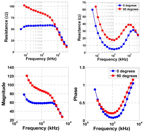
The results obtained when the EIM measurement system was used to evaluate the impedance of beef (flank steak) are presented in Figure 5. The expected anisotropy of current propagation in muscle tissue is clearly identifiable. Measurements are made both aligned to the direction of the muscle fibers (0°) and perpendicular to it (90°). Below 1 MHz, both the resistance and reactance at 0° is noticeably lower than at 90°.
Fig. 5.
Impedance plots showing the anisotropic current conduction properties of muscle tissue. The test was carried out using a piece of beef which shows clear muscle fiber bundles.
Intuitively, this result is expected since current propagation perpendicular to the muscle fibers will require conduction across many muscle cell membranes, each of which adds resistance and capacitance. On the other hand, when current propagates along the muscle fibers it will flow mainly through the low-resistance, low-capacitance extracellular space and cell cytoplasm.
Time consuming calibration of the EIM probe for use with different patients or for use with the same patient on different days is not necessary. The quantity used in EIM is the phase of the measured impedance which removes the need to use the actual magnitude of impedance to evaluate the progress of neuromuscular disease [6]. In addition, the contribution of fat and skin to the measured impedance appears as a fixed error added to measurements taken at every angle. Hence, the influence of this error is mitigated since it affects all measurements equally.
V. Conclusion
This work has presented an improved electrical impedance myography measurement system for the assessment of neuromuscular disease. Simultaneous impedance measurements at multiple frequencies and multiple angles were implemented to improve the measurement speed over the first generation EIM system. The development of a portable, handheld impedance device will help refine EIM into an easily applied, sophisticated diagnostic tool. The simultaneous measurement of impedance at multiple frequencies using a reconfigurable electrode array will ensure that EIM measurements are robust, rapidly obtained, and highly reliable.
Acknowledgments
We thank the Center for Integration of Medicine and Innovative Technology for funding part of this work
We thank the Microsystems Technology Laboratories, MIT for use of laboratory equipment.
This work was supported in part by the Center for Integration of Medicine and Innovative Technology (CIMIT).
References
- 1.Chumlea WC, Guo SS. Bioelectrical-Impedance and Body-Composition - Present Status and Future-Directions. Nutrition Reviews. 1994 Apr ;52:123–131. doi: 10.1111/j.1753-4887.1994.tb01404.x. [DOI] [PubMed] [Google Scholar]
- 2.Wilson AJ, Milnes P, Waterworth AR, Smallwood RH, Brown BH. Mk3.5: a modular, multi-frequency successor to the Mk3a EIS/EIT system. Physiological Measurement. 2001 Feb;22:49–54. doi: 10.1088/0967-3334/22/1/307. [DOI] [PubMed] [Google Scholar]
- 3.Li JH, Joppek C, Faust U. In vivo EIT electrode system with 32 interlaced active electrodes. Medical & Biological Engineering & Computing. 1996 May;34:253–256. doi: 10.1007/BF02520083. [DOI] [PubMed] [Google Scholar]
- 4.Forbes GB, Simon W, Amatruda JM. Is Bioimpedance a Good Predictor of Body-Composition Change. American Journal of Clinical Nutrition. 1992 Jul;56:4–6. doi: 10.1093/ajcn/56.1.4. [DOI] [PubMed] [Google Scholar]
- 5.Aaron R, Huang M, Shiffman CA. Anisotropy of human muscle via non-invasive impedance measurements. Physics in Medicine and Biology. 1997 Jul;42:1245–1262. doi: 10.1088/0031-9155/42/7/002. [DOI] [PubMed] [Google Scholar]
- 6.Rutkove SB, Aaron R, Shiffman CA. Localized bioimpedance analysis in the evaluation of neuromuscular disease. Muscle & Nerve. 2002 Mar;25:390–397. doi: 10.1002/mus.10048. [DOI] [PubMed] [Google Scholar]
- 7.Shiffman CA, Aaron R. Angular dependence of resistance in non-invasive electrical measurements of human muscle: the tensor model. Physics in Medicine and Biology. 1998 May;43:1317–1323. doi: 10.1088/0031-9155/43/5/019. [DOI] [PubMed] [Google Scholar]
- 8.Chin AB, Garmirian LP, Nie R, Rutkove SB. Optimizing Measurement of the Electrical Anisotropy of Muscle. Muscle & Nerve. 2008 doi: 10.1002/mus.20981. (Accepted) [DOI] [PMC free article] [PubMed] [Google Scholar]
- 9.Rutkove SB, Aaron R, Partida RA, Esper GJ, Shiffman CA. Electrical impedance myography: A new tool in the assessment of radiculopathy. Muscle & Nerve. 2004 Oct;30:514–514. [Google Scholar]
- 10.Rutkove SB, Aaron R, Raynor EM, Shefner JM, Cudkowicz ME, Schoenfeld DA, Bron D, Woodman KH, Shiffman CA. Electrical impedance myography as an outcome measure in ALS clinical trials. Neurology. 2006 Mar 14;66:A246–A246. [Google Scholar]
- 11.Rutkove SB, Lee KS, Shiffman CA, Aaron R. Test-retest reproducibility of 50 kHz linear-electrical impedance myography. Clinical Neurophysiology. 2006 Jun;117:1244–1248. doi: 10.1016/j.clinph.2005.12.029. [DOI] [PubMed] [Google Scholar]
- 12.Rutkove SB, Partida RA, Aaron R, Esper GJ, Shiffman CA. Multifrequency electrical impedance myography: Early results in two patients. Muscle & Nerve. 2004 Oct;30:531–531. [Google Scholar]
- 13.Rutkove SB, Tarulli AW, Chin AB, Aaron R, Shiffman CA. Electrical impedance myography: A new methodology for the study of neuromuscular disease. Annals of Neurology. 2007;62:S10–S10. [Google Scholar]
- 14.Rutkove SB, Zhang H, Schoenfeld DA, Raynor EM, Shefner JM, Cudkowicz ME, Chin AB, Aaron R, Shiffman CA. Electrical impedance myography to assess outcome in amyotrophic lateral sclerosis clinical trials. Clinical Neurophysiology. 2007 Nov;118:2413–2418. doi: 10.1016/j.clinph.2007.08.004. [DOI] [PMC free article] [PubMed] [Google Scholar]
- 15.Tarulli A, Esper GJ, Lee KS, Aaron R, Shiffman CA, Rutkove SB. Electrical impedance myography in the bedside assessment of inflammatory myopathy. Neurology. 2005 Aug 9;65:451–452. doi: 10.1212/01.wnl.0000172338.95064.cb. [DOI] [PubMed] [Google Scholar]
- 16.Raposa G. Performing AC Impedance Measurements on Fuel Cells. Fuel Cell. Feb 2003; http://www.fuelcell-magazine.com/eprints/free/agilentfeb03.pdf.


