Abstract
Optical coherence tomography (OCT) is being employed more and more often to image pathologies and surgical anatomy within the anterior segment, specifically in anterior chamber biometry, corneal pachymetric mapping, angle evaluation and high-resolution cross-sectional imaging. The cross-sectional imaging capability of OCT is similar to ultrasound, but its higher resolution allows OCT to measure and visualize very fine anatomic structures. No contact is required. In this review, we describe the utility and limitations of anterior segment OCT.
Keywords: anterior chamber, clinical applications, cornea, optical coherence tomography
INTRODUCTION
Optical coherence tomography (OCT) is a non-contact imaging technology that provides detailed cross-sectional images (tomography) of internal structures in biological tissues.1 In 1994, Izatt et al. published the first report of OCT imaging of corneal and anterior segment.2 Since then, the increasing popularity of corneal refractive surgery has spurred many investigators to apply OCT to corneal imaging and refine the instrumentation for an anterior segment OCT. Other important applications, such as angle evaluation (to diagnose narrow-angle glaucoma) and anterior chamber (AC) biometry (to plan out intraocular lens, or IOL, implantation) have driven this field of research even further. In this review, we discuss the major clinical and research applications of anterior segment OCT.
PRINCIPLES AND CHARACTERISTICS OF OPTICAL COHERENCE TOMOGRAPHY
Optical coherence tomography imaging is based on measuring the delay of light (typically infrared) reflected from tissue structures. Its principle is similar to that of ultrasound or radar imaging, in which the round trip delay time of the reflected wave is used to probe the target structure in depth. Because light travels extremely fast, it is not possible to directly measure the delay at a micron resolution. Therefore, OCT employs low-coherence interferometry to compare the delay of tissue reflections against a reference reflection. To obtain an OCT image, the instrument scans a light beam laterally, creating a series of axial scans (A-scans), after which it combines these A-scans into a composite image. Each A-scan contains information on the strength of reflected signal as a function of depth.
The main characteristics of OCT are as follows:
Ophthalmic OCT typically uses infrared wavelengths that do not dazzle the subject. OCT imaging of the retina, where passage through the ocular media is good, typically involves wavelengths between 800 and 900 nm. For anterior segment imaging, it is advantageous to use a longer wavelength, 1310 nm; in this case, the higher power is safe, because water absorption blocks some of the retinal exposure.
Compared with other imaging modalities, OCT has a higher-depth resolution. Resolution is determined by the wavelength and the spectral bandwidth of the light source, which is typically a superluminescent diode. Shorter wavelengths and wider bandwidths provide better resolution.
The interference itself requires a strict phase relationship between the interfering waves. Multiple scattered events lose the phase information, so only single scattered photons contribute to the interference. Consequently, the maximum OCT penetration depth is the depth from which single scattered photons still originate, and scattering in turbid media (e.g. sclera, iris) primarily limits the penetration depth of this technique. Because scattering is lower at longer wavelengths, using longer wavelength light sources improves the penetration of anterior segment OCT.
OCT is more sensitive than other imaging techniques by using a similar principle, because photodetection at the interferometer output involves multiplying the two optical waves together. Therefore, the weak signal in the object arm, back-scattered or transmitted through the tissue, is amplified by the strong signal in the reference arm. This characteristic explains how OCT can typically detect reflected signals as small as one part in 10−10 of the incident power.
The resolution of OCT is very high, ranging from 2 to 20 µm, making it ideal for imaging and measuring small eye structures.
TIME-DOMAIN VERSUS FOURIER-DOMAIN OPTICAL COHERENCE TOMOGRAPHY
In time-domain (TD) OCT, the A-scans are produced by varying the position of the reference mirror, thereby producing a reflectivity profile corresponding to depth. Each depth in the tissue is detected serially. In Fourier-domain (FD) OCT, the reference mirror is fixed, and the interference between the sample and reference reflections is detected as a spectrum. Fourier transformation of the spectral interferogram produces the A-scan. Current ophthalmic FD-OCT systems utilize a spectrometer in the detector arm of the interferometer. Scanning the spectrum of the light source (swept-source OCT) is another FD-OCT implementation that might become more economical as the technology advances.
Because TD-OCT systems depend on the mechanical movement of a reference mirror to measure the reflectivity of the tissues, the speed of these systems is limited by the mechanical cycle time of the reference mirror driver. Currently, the fastest commercial TD-OCT system is the Visante anterior segment OCT (Carl Zeiss Meditec, Inc., Dublin, CA), which acquires 2000 A-scans per second. In contrast, FD-OCT uses a stationary reference mirror, which poses no mechanical limitations. The RTVue (Optovue, Inc., Fremont, CA) is an FD-OCT system that can be used for either retinal or anterior segment imaging (when used with a corneal adaptor module, or CAM). Its spectrometer is fitted with a high-speed line camera that captures 26 000 A-scans per second. FD-OCT is not only faster than TD-OCT, but it is also much more efficient: it detects signals from the entire depth range in parallel, rather than serially, thereby achieving higher speed without losing signal-to-noise ratio.
Although the Visante is slower, its longer wavelength (1310 nm, compared with the 830-nm RTVue) penetrates more deeply through the sclera and iris. Its 16-mm scan width and almost 6-mm scan depth in tissue are sufficient for AC biometry. The Visante′s depth resolution is approximately 17 µm full-width-half-maximum in tissue. On the other hand, the RTVue is 13 times faster and boasts a depth resolution that is over three times higher (5 µm) than the Visante. The high speed reduces motion error and yields higher definition (more A-scans per image), producing much more detailed images and a more precise mapping of corneal thickness. The RTVue is fast enough to directly measure anterior and posterior corneal power.3 Each OCT design has distinct advantages, and which of the current imaging instruments is a better choice depends on the application.
ECTATIC DISORDERS
Keratoconus, the most common ectatic disorder, is characterized by bilateral and progressive corneal thinning and apical protrusion. In general, the focal thinning occurs in the inferotemporal corneal location, and detecting this characteristic corneal thinning pattern is a useful new approach to diagnose keratoconus.
Although moderate to advanced keratoconus is easily recognized by the characteristic topographic pattern and classic clinical signs, it can be difficult to distinguish subclinical forms of the disease from normal corneas, because patients usually present with normal visual acuity, stable topographic patterns and minimal or no clinical signs.4 In these cases, OCT produces highly reliable pachymetry maps5,6 that can detect keratoconus, ectasia and corneal thinning conditions before refractive laser surgeries.
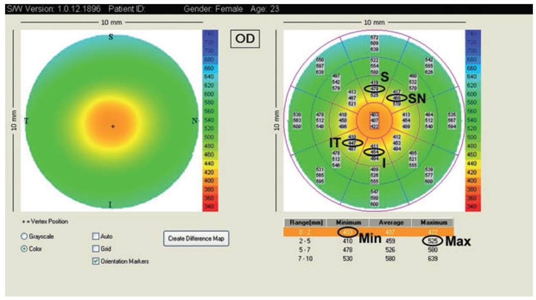
Optical coherence tomography can diagnose keratoconus by using four parameters, based on the central 5-mm diameter region of the pachymetry map (Fig. 1):
I–S: the average thickness of the inferior (I) octant minus the average thickness of the superior (S) octant
IT–SN: the average thickness of the inferotemporal (IT) octant minus the average thickness of the superonasal (SN) octant
Minimum: the thinnest corneal thickness
Minimum–maximum: the minimum pachymetry minus the maximum pachymetry.
Figure 1.
Visante optical coherence tomography pachymetry map and the parameters used to detect keratoconus. I, inferior; IT, inferotemporally; Max, maximum; Min, minimum; S, superior; SN, superonasal.
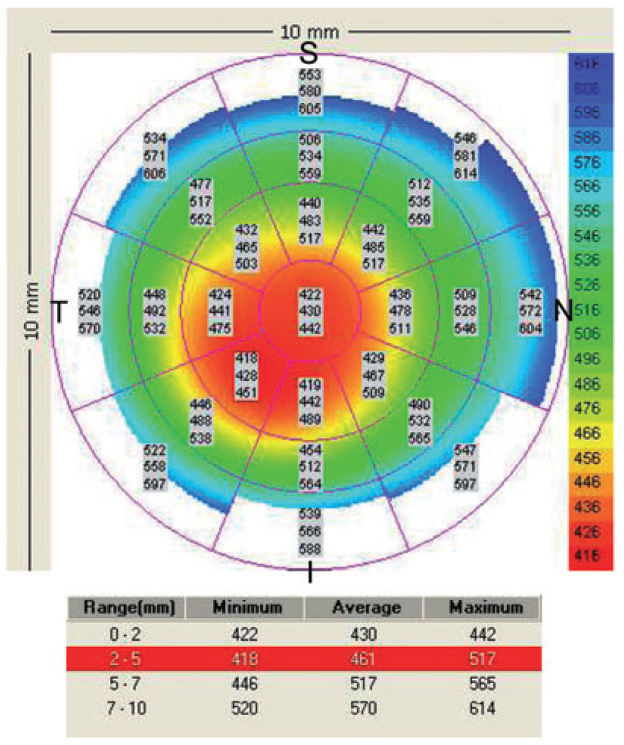
Combining these four parameters detects asymmetry, global thinning and focal thinning, and we have developed diagnostic cut-off points for these parameters.7,8 Asymmetry that is more negative than −45 µm for I–S or IT–SN indicates keratoconus, as does a minimum thickness of less than 470 µm or a minimum–maximum difference that is more negative than −100 µm. One abnormal parameter provides reason to suspect keratoconus, and two or more abnormal parameters provide a definitive diagnosis. An example of a pachymetry map from an eye with keratoconus is shown in Figure 2.
Figure 2.
Visante pachymetry map of a keratoconic eye with a central thinning. I − S = 442 − 483 = −41 µm; IT − SN = 428 − 485 = −57 µm; Min = 422 µm; Min − Max = 422 − 517 = −99 µm. The pachymetry map was abnormal in two indices (IT–SN and Min); a third index was borderline (Min–Max), in that it fell below keratoconus diagnostic cut-off values. I, inferior; IT, inferotemporal; Max, maximum; Min, minimum; S, superior; SN, superonasal.
LASER IN SITU KERATOMILEUSIS (LASIK) FLAPS EVALUATION
Corneal ectasia post-laser vision correction is a serious complication described in the literature. An abnormal preoperative corneal topography that is suspicious for keratoconus, insufficient residual stromal bed thickness (less than 250 µm)9 and reduction of the biomechanical integrity of the cornea are the most important risk factors for keratectasia.
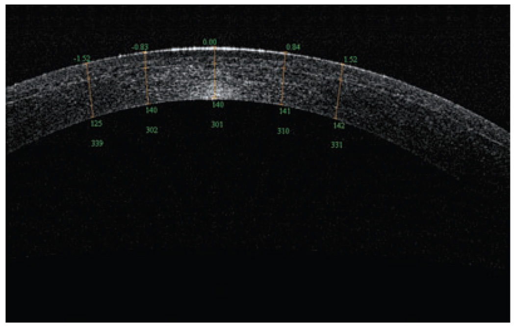
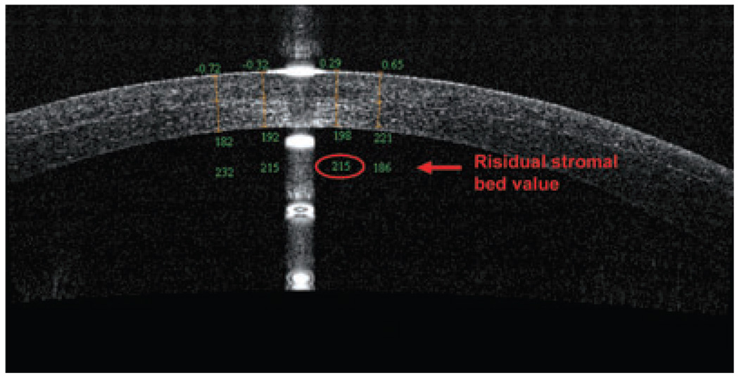
An OCT evaluation of the residual stromal bed and flap can assess the potential safety of performing an enhancement by lifting the flap. Specifically, OCT is able to visualize the LASIK flap in the early postoperative period to evaluate the performance of microkeratome or femtosecond laser being used; it can also visualize the flaps many months later. In a recent study, Li et al. showed OCT scans at 1 day and 1 week after surgery, and the LASIK flaps were detectable in all flap profile and flap map scans.10 Although the flap boundary detection rate decreased to 61% at 3 months and 42% at 6 months, the OCT could measure the flap thickness at all time points for every subject. Figure 3 shows a flap created by a femtosecond laser that, at 1 week postoperative, exhibited a residual stromal bed of 301 µm. In contrast, the OCT in Figure 4 revealed a LASIK flap of 198 µm, which was much thicker than intended; OCT also measured the residual stromal bed at 215 µm, which puts this cornea at high risk for ectasia in the future.
Figure 3.
Optical coherence tomography scan (RTVue) of an Intra-laser flap, 1 week postoperative, with a 301-µm residual stromal bed.
Figure 4.
Optical coherence tomography scan (RTVue) of a right cornea with a thick flap and a thin residual stromal bed (<250 µm).
ANTERIOR CHAMBER BIOMETRY
Measurements of AC dimensions are important for refractive surgery and diagnostics. Accurate measurement and biometric analyses of the anterior segment of the eye have become extremely critical, because of the increased use of refractive phakic and pseudophakic IOLs.11 Accurate AC biometry also allows the clinician to select the appropriate-sized IOL, in order to avoid complications.
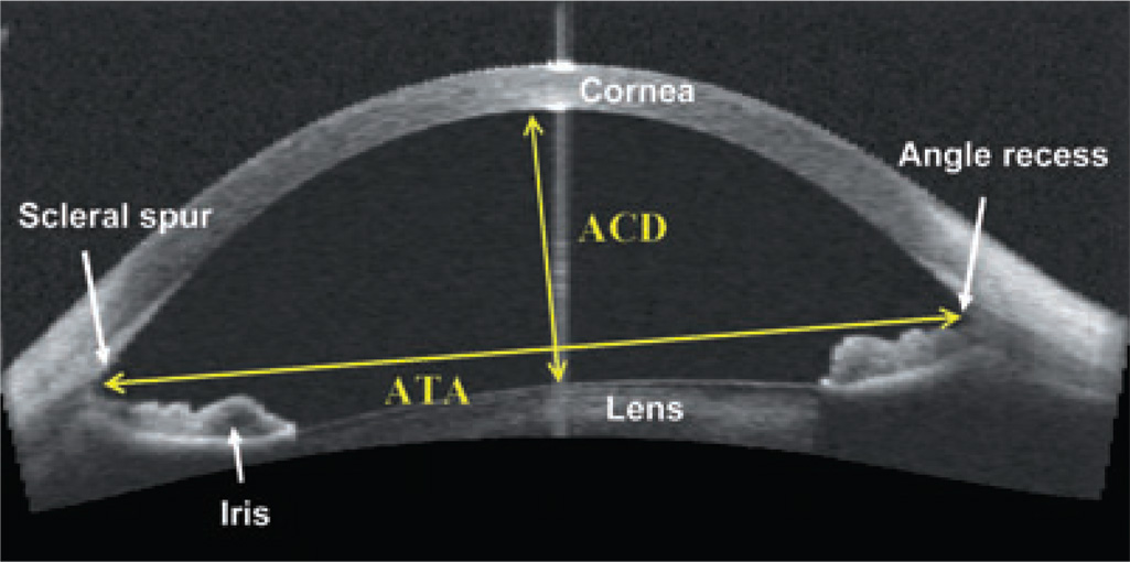
Its high image resolution makes OCT ideal for accurate AC measurement and reproducibility. Unlike ultrasound, OCT is a non-contact exam, eliminating discomfort and distortion from probe contact or immersion. OCT can image the entire AC and yield measurements such as AC depth, angle-to-angle width and iris profile (Fig. 5). Furthermore, in a study by Kohnen et al., OCT yielded more accurate real AC width values than corneal diameter measurements with the Orbscan (Bausch & Lomb-Orbtek, Salt Lake City, UT, USA) or IOLMaster (Carl Zeiss, Dublin, CA, USA), which only estimated AC width.12 Goldsmith et al. used a high-speed OCT prototype to measure mean AC width, AC depth and crystalline lens vault measurements in 40 normal eyes; the AC width was 12.53 ± 0.47 mm, with high repeatability between images (standard deviation [SD], 0.134 mm). Furthermore, the mean AC depth was 2.99 ± 0.323 mm (inter-eye SD), with repeatability of less than 0.001 mm (inter-image SD), and the mean crystalline lens vault was 0.39 ± 0.27 mm, with 0.023 mm repeatability.13 Despite its numerous applications, OCT technology does possess one distinct disadvantage: it cannot measure and detect structures behind the iris very well.
Figure 5.
Visante optical coherence tomography of an anterior chamber measurement in a phakic patient. ACD, anterior chamber depth; ATA, angle-to-angle width.
ANGLE ASSESSMENT
Various studies have used different classification systems to evaluate and quantify the AC angle, the ‘gold standards’ of which are the gonioscopy in combination with a Goldmann contact lens examination, and the classification system introduced by Shaffer.14 However, in this system, the examiner numerically estimates the AC angle based on anatomic landmarks, which is subjective and highly dependent on the examiner’s judgment and experience.
Previous reports have described several parameters to quantify normal AC angle using OCT and ultrasound biomicroscopy (UBM):15–17
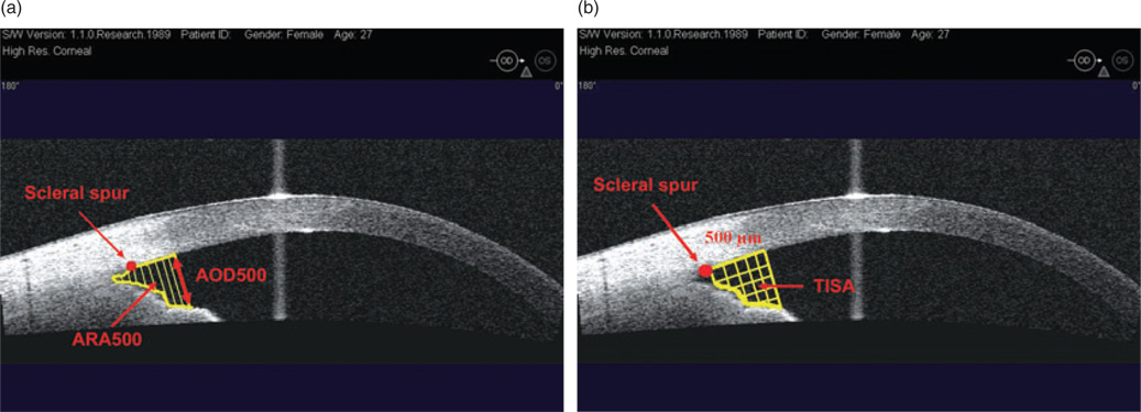
Angle opening distance at 500 µm (AOD 500) is defined as the linear distance between the trabecular meshwork and the iris at 500 µm anterior to the scleral spur.
Angle recess area at 500 µm and 750 µm (ARA 500 and ARA 750) is the triangular area formed by theAOD500 orAOD750 (the base), the angle recess (the apex), the iris surface and the inner corneo-scleral wall (the sides of triangle; Fig. 6a). Theoretically, ARA is a better measurement parameter than AOD, because it accounts for the whole contour of the iris surface, rather than measuring at a single point on the iris.
Trabeculo-iris space area at 500 µm and 750 µm (TISA 500 and TISA 750) is a trapezoidal area with the following boundaries: the anterior AOD 500 or AOD 750, a posterior line drawn from the scleral spur perpendicular to the plane of the inner scleral wall to the opposing iris, the superior inner corneo-scleral wall and the inferior iris surface. This parameter may better represent the actual filtering area compared with ARA, because TISA excludes the non-filtering region behind the scleral spur (Fig. 6b).
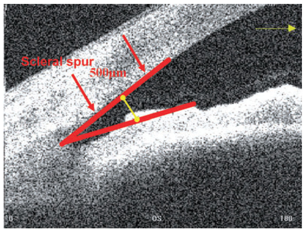
AC angle in degrees, in which the angle recess forms the apex of the AC angle, and the two arms are formed by drawing lines through the points defining the AOD 500 (Fig. 7).
Figure 6.
(a) Visante optical coherence tomography image of an anterior chamber angle: angle open distance (AOD) and angle recess area (ARA); (b) trabeculo-iris space area (TISA). Does not include the area posterior to the scleral spur.
Figure 7.
Anterior chamber angle, in degrees (Visante optical coherence tomography).
Goniometry studies quantified a normal eye as one in which the open angle has a ~329-µ1m AOD 500 and a ~28° AC angle.18 In narrow and closed angles, the AOD 500 is <210 µm and the AC angle is <18°. Radhakrishnan et al. in a study of 31 eyes found that an AOD 500 cut-off value of 190 µm was 100% sensitive and 87.5% specific in detecting an occludable angle.16 Thus, this criterion suggests that an AOD 500 of <190 µm is occludable.
In recent years, several studies have used anterior segment OCT to visualize AC angle structures.2,13,19,20 The non-contact nature of OCT permits comfortable and safe exams and, more importantly, sidesteps mechanical distortion of the angle and improves the reliability of the angle depth measurement. This technique provides high-resolution cross-sectional images, and it yields reproducible and accurate measurements of the AC.13,21
In October 2005, Food and Drug Administration approved the commercially available Visante OCT for AC angle imaging. This apparatus uses a 1300-nm wavelength and acquires images at a rate of eight frames (2000 A-scans) per second with a transverse resolution of 60 µm and an axial resolution of 10–20 µm. Recent studies with Visante OCT determined that this apparatus could pinpoint scleral spur locations in 72% of eye images.22,23 Its location on anterior segment OCT images was less detectable in quadrants with a closed angle during gonioscopy, or in images obtained in areas that were superior or inferior of the nasal and temporal quadrants. This inability to detect scleral spur may hamper quantitative analysis of AC angle parameters that are dependent on spur location, particularly in the superior and inferior quadrants. Indeed, in a second study, the same authors could not classify the AC angle in 16% of the eyes because of poor image quality or poor scleral spur definition.
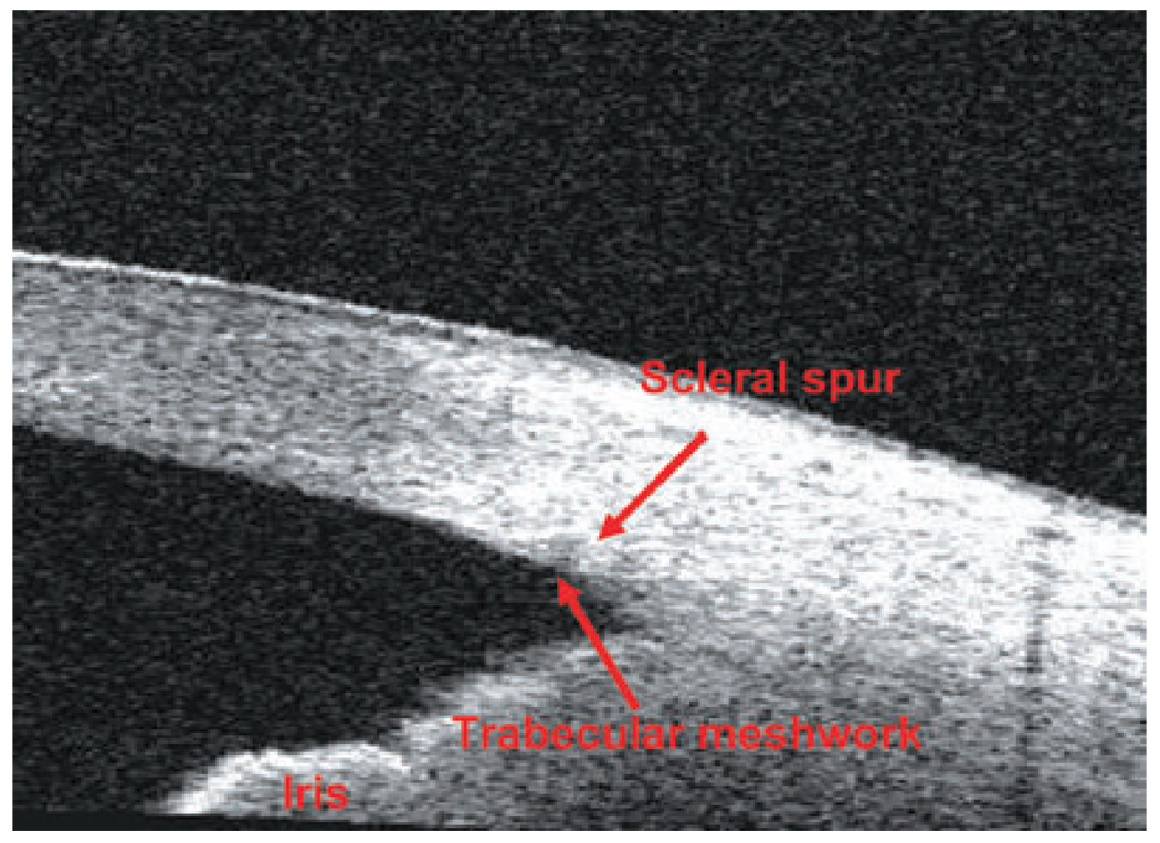
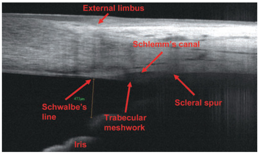
A recently approved FD-OCT (September 2007), RTVue, exhibits an 830-nm wavelength, 26000 A-scans per second and an axial resolution of 5 µm, rendering it able to visualize scleral spur and other small anatomic details of the angle chamber (such as the Schlemm’s canal, the Schwalbe’s line and the trabecular meshwork) with higher resolution and image quality than the Visante OCT. Figure 8 and Figure 9 show TD-OCT and FD-OCT angle scans, respectively. In both images, the structures in the posterior chamber are not well delineated because of attenuation of the OCT light beam by the iris pigment epithelium.
Figure 8.
Time-domain optical coherence tomography (Visante) angle scan.
Figure 9.
Fourier-domain optical coherence tomography (RTVue) angle scan.
CORNEAL AND SCLERAL ABNORMALITIES
Optical coherence tomography accurately maps corneal thickness in clear and opacified corneas, allowing the examiner to precisely map the depth of corneal opacities, the degree of epithelial hyperplasia and the thickness of the cornea, as well as scleral melts, corneal degenerations, scars and corneal dystrophies.5,6 The OCT images can facilitate decision-making by the surgeons and allow them to more accurately plan treatments for corneal opacities. For example, scars within the optical zone generally respond well to ablative treatment, but only if they can be removed while maintaining a minimal corneal thickness of 300 µm (including the epithelium). We must also consider the resulting hyperopic shift, the possibility of inducing a regular or irregular astigmatism and the feasibility of subsequent spectacles, rigid gas-permeable lenses or photorefractive keratectomy (PRK) treatments to achieve improved overall vision. OCT can reveal whether the opacity is too deep, in which case lamellar or penetrating keratoplasty (PK) may be an alternative.
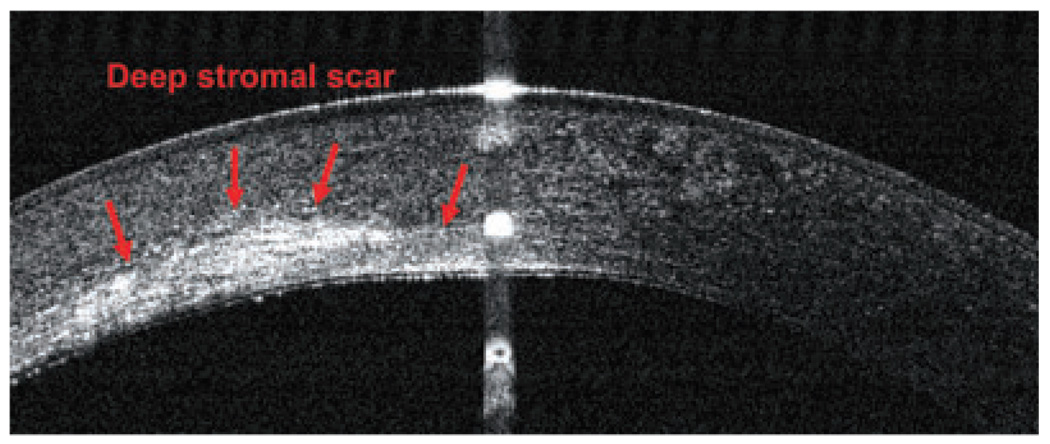
For example, Figure 10 shows a left eye with a deep stromal scar in the cornea; it had initially been referred for phototherapeutic keratectomy (PTK) treatment. A subsequent OCT scan revealed deep posterior stromal scars, which contraindicated PTK treatment and suggested PK as a better alternative. In Figure 11, a patient with granular dystrophy in both eyes was OCT scanned during preoperative PTK testing, and the images revealed the upper boundary of the transepithelial ablation, in order to reduce surface irregularity. In this case, the scan indicated transepithelial PTK ablation as an excellent method for smoothing corneal surface abnormalities, especially small depressions and irregularities.
Figure 10.
Optical coherence tomography image (RTVue) of a deep stromal scar in a left eye.
Figure 11.
Granular dystrophy in both eyes of one patient: (a) right eye; (b) left eye (RTVue).
INTRASTROMAL CORNEAL RINGS
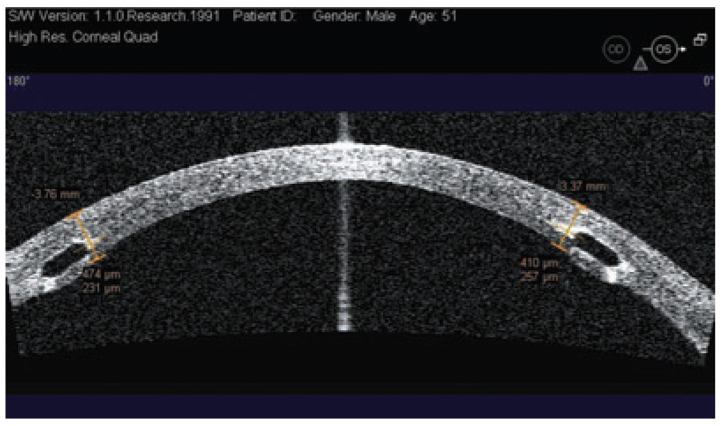
Intrastromal corneal rings segments have been proposed and investigated as an additive surgical procedure for correcting keratoconus; such an approach could provide an alternative to delaying or avoiding corneal grafting.24–27 The rings, a pair of 150° polymethylmethacrylate arc segments, are designed to be implanted into surgically created channels in the mid-peripheral cornea (~70% depth) in order to flatten the cornea.27 In some studies, these intrastromal corneal rings have improved the best spectacle-correction visual acuity of keratoconic eyes an average of two lines.28–30 The surgeon uses a slitlamp impression to evaluate ring segment depth, but this technique may not accurately assess segment depth. In contrast, high-resolution OCT can image the intrastromal corneal rings, providing a much more accurate depth and position assessment (Fig. 12). If the surgeon does not place the intrastromal corneal ring segments deep enough, it may result in severe complications, such as epithelial-stromal breakdown and extrusion.31,32 On the other hand, implants that are too deep may carry a high risk for perforating into the AC.32 Hence, the OCT scan can help cornea surgeons improve their techniques and avoid depth-related problems earlier.
Figure 12.
Horizontal Visante optical coherence tomography cross-section and measurement of the intrastromal ring depth. Both rings are placed at an adequate depth.
CORNEAL TRANSPLANTATION
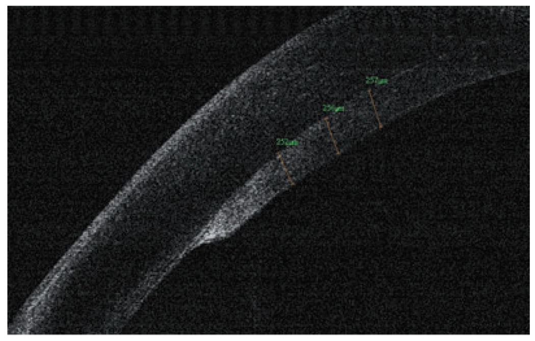
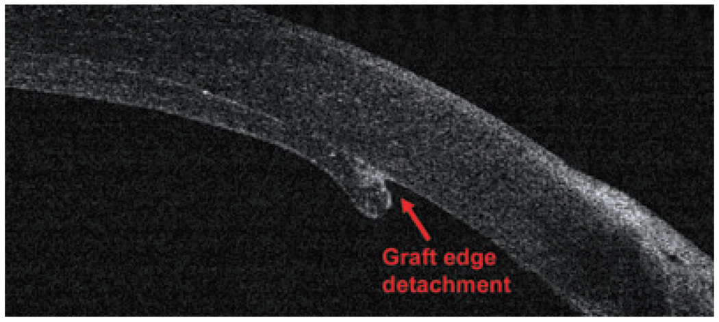
The new generation of corneal transplant procedures, such as full-thickness PK with incisions shaped by femtosecond lasers, descemet-stripping endothelial keratoplasty (DSEK) and deep lamellar endothelial keratoplasty (DLEK), have been improving results and resulting in faster vision recovery. In these techniques, OCT has proven to be a critical preoperative and postoperative tool to evaluate, refine and manage corneal transplantation patients. OCT can image the creation of the donor flap and measure the thickness prior to DSEK and DLEK. Moreover, it provides corneal measurements, pachymetry maps, interface abnormalities; it also verifies draft attachment (Fig 13, Fig 14) and visualizes the donor button dislocation postoperatively. In PK with femtosecond laser applications, OCT can identify top hat, mushroom, zigzag-shaped incisions, alignment of donor and host cornea and the depth of the sutures.33,34
Figure 13.
Optical coherence tomography graft measurement, 1 month after a successful descemet-stripping endothelial keratoplasty surgery (RTVue).
Figure 14.
A small graft edge detachment after a descemet-stripping endothelial keratoplasty surgery (RTVue).
ANTERIOR SEGMENT TUMOURS
Ultrasound and OCT technologies can usually image anterior segment tumours, but OCT exhibits many distinct advantages.35 It does not require water immersion or direct probe contact to the eye, which eliminates the associated image distortion and provides higher spatial resolution than UBM. With devices utilizing a longer wavelength source (1310 nm), the OCT beam can penetrate and provide detailed images of the iris, limbus and anterior segment angle. Comparative studies that evaluated OCT, UBM and slit lamp photography demonstrated that OCT technology is more accurate and more repeatable in anterior segment biometry.13,16,18,36 Although OCT is limited by its lower penetration through sclera and poor visualization of the ciliary body, it can visualize and monitor iris cysts, iris nevus, iris melanoma, iridoschisis and even some tumours of the ciliary body, although UBM is still better for determining the extent of the most ciliary body tumours.
THE FUTURE OF ANTERIOR SEGMENT OPTICAL COHERENCE TOMOGRAPHY
The new generation of FD-OCT devices for anterior segment has arrived, bringing with it dramatically increased image-acquisition speeds and the promise of improved diagnostics. The recent incorporation of this generation of OCT instruments into ophthalmology clinics has boosted the sensitivity of diagnosis, improved disease progression monitoring, facilitated surgical planning and enhanced the response to therapy. Because these new FD-OCT devices magnify speed and resolution and expand the repertoire of diagnostic wavelengths, they might pave the way for future technologies that yield better images of structures behind the iris, such as the ciliary body, ciliary sulcus and peripheral retina. OCT may someday produce images of microscopic structures, such as endothelial cells, corneal nerves, protozoa and fungi, permitting a non-excisional ‘optical biopsy’. These advances may also allow us to exactly calculate corneal power, IOL in patients who had prior laser vision correction (both of these studies are in progress) and topographic corneal evaluations. New developments in three-dimensional visualization of AC tissue morphology, by using future OCT models with ultra-high speed and resolution, may further enhance the diagnostic role of this powerful technology in ophthalmology clinics.
CONCLUSION
In summary, OCT is applicable to assess a wide variety of corneal and anterior segment conditions. This technology has revolutionized our ability to examine the AC, cornea and surrounding areas. The versatility, accuracy and high resolution of these imaging devices has facilitated and enhanced diagnosis, surgical planning, clinical evaluations, patient management and therapeutic decisions. We believe that OCT will eventually encompass more of the applications currently performed with other technologies.
ACKNOWLEDGEMENTS
This study was financially supported by NIH grants R01 EY018184 and P30 EY03040; a grant from Optovue, Inc.; a unrestricted grant from Research to Prevent Blindness, Inc.; and endowment funding from the Charles C. Manger III, MD Chair in Corneal Laser Surgery.
Footnotes
Proprietary interests: David Huang receives royalty from a patent on optical coherence tomography licensed to Carl Zeiss Meditec, Inc. Yan Li, and David Huang receive grant support from Optovue, Inc; David Huang also received stock options and travel support from Optovue.
REFERENCES
- 1.Huang D, Swanson EA, Lin CP, et al. Optical coherence tomography. Science. 1991;254:1178–1181. doi: 10.1126/science.1957169. [DOI] [PMC free article] [PubMed] [Google Scholar]
- 2.Izatt JA, Hee MR, Swanson EA, et al. Micrometer-scale resolution imaging of the anterior eye in vivo with optical coherence tomography. Arch Ophthalmol. 1994;112:1584–1589. doi: 10.1001/archopht.1994.01090240090031. [DOI] [PubMed] [Google Scholar]
- 3.Huang D, et al. Corneal Power Measurement with Optical Coherence Tomography; Paper presented at the Association for Research in Vision and Ophthalmology Meeting; Fort Lauderdale, FL. 2008. [Google Scholar]
- 4.Ambrosio R, Jr, Alonso RS, Luz A, Coca Velarde LG. Corneal-thickness spatial profile and corneal-volume distribution: tomographic indices to detect keratoconus. J Cataract Refract Surg. 2006;32:1851–1859. doi: 10.1016/j.jcrs.2006.06.025. [DOI] [PubMed] [Google Scholar]
- 5.Khurana RN, Li Y, Tang M, Lai MM, Huang D. High-speed optical coherence tomography of corneal opacities. Ophthalmology. 2007;114:1278–1285. doi: 10.1016/j.ophtha.2006.10.033. [DOI] [PubMed] [Google Scholar]
- 6.Li Y, Shekhar R, Huang D. Corneal pachymetry mapping with high-speed optical coherence tomography. Ophthalmology. 2006;113:792–799. doi: 10.1016/j.ophtha.2006.01.048. e2. [DOI] [PMC free article] [PubMed] [Google Scholar]
- 7.Li Y. Keratoconus Screening with High-Speed Optical Coherence Tomography; Paper presented at the Association for Research in Vision and Ophthalmology Meeting; Fort Lauderdale, FL. 2007. [Google Scholar]
- 8.Steinert R, Huang D. Anterior Segment Optical Coherence Tomography. 1st edn. Thorofare, NJ: Slack Inc.; 2008. [Google Scholar]
- 9.Randleman JB, Russel B, Ward MA, Thompson KP, Stulting RD. Risk factors and prognosis for corneal ectasia after LASIK. Ophthalmology. 2003;110:267–275. doi: 10.1016/S0161-6420(02)01727-X. [DOI] [PubMed] [Google Scholar]
- 10.Li Y, Netto MV, Shekhar R, Krueger RR, Huang D. A longitudinal study of LASIK flap and stromal thickness with high-speed optical coherence tomography. Ophthalmology. 2007;114:1124–1132. doi: 10.1016/j.ophtha.2006.09.031. [DOI] [PubMed] [Google Scholar]
- 11.O’Brien TP, Awwad ST. Phakic intraocular lenses and refractory lensectomy for myopia. Curr Opin Ophthalmol. 2002;13:264–270. doi: 10.1097/00055735-200208000-00015. [DOI] [PubMed] [Google Scholar]
- 12.Kohnen T, Thomala MC, Cichocki M, Strenger A. Internal anterior chamber diameter using optical coherence tomography compared with white-to-white distances using automated measurements. J Cataract Refract Surg. 2006;32:1809–1813. doi: 10.1016/j.jcrs.2006.08.023. [DOI] [PubMed] [Google Scholar]
- 13.Goldsmith JA, Li Y, Chalita MR, et al. Anterior chamber width measurement by high-speed optical coherence tomography. Ophthalmology. 2005;112:238–244. doi: 10.1016/j.ophtha.2004.09.019. [DOI] [PMC free article] [PubMed] [Google Scholar]
- 14.Shaffer RN. A new classification of the glaucomas. Trans Am Ophthalmol Soc. 1960;58:219–225. [PMC free article] [PubMed] [Google Scholar]
- 15.Pavlin CJ, Harasiewicz K, Foster FS. Ultrasound biomicroscopy of anterior segment structures in normal and glaucomatous eyes. Am J Ophthalmol. 1992;113:381–389. doi: 10.1016/s0002-9394(14)76159-8. [DOI] [PubMed] [Google Scholar]
- 16.Radhakrishnan S, Goldmith J, Huang D, et al. Comparison of optical coherence tomography and ultrasound biomicroscopy for detection of narrow anterior chamber angles. Arch Ophthalmol. 2005;123:1050–1059. doi: 10.1001/archopht.123.8.1053. [DOI] [PubMed] [Google Scholar]
- 17.Ishikawa H, Liebmann JM, Ritch R. Quantitative assessment of the anterior segment using ultrasound biomicroscopy. Curr Opin Ophthalmol. 2000;11:133–139. doi: 10.1097/00055735-200004000-00012. [DOI] [PubMed] [Google Scholar]
- 18.Wirbelauer C, Karandish A, Haberle H, Pham DT. Noncontact goniometry with optical coherence tomography. Arch Ophthalmol. 2005;123:179–185. doi: 10.1001/archopht.123.2.179. [DOI] [PubMed] [Google Scholar]
- 19.Hoerauf H, Goroles RS, Scholz C, et al. First experimental and clinical results with transscleral optical coherence tomography. Ophthalmic Surg Lasers. 2000;31:218–222. [PubMed] [Google Scholar]
- 20.Hoerauf H, Winkler J, Scholz C, et al. Transscleral optical coherence tomography: a new imaging method for the anterior segment of the eye. Arch Ophthalmol. 2002;120:816–819. doi: 10.1001/archopht.120.6.816. [DOI] [PubMed] [Google Scholar]
- 21.Muller M, Dahmen G, Porksen E, et al. Anterior chamber angle measurement with optical coherence tomography: intraobserver and interobserver variability. J Cataract Refract Surg. 2006;32:1803–1808. doi: 10.1016/j.jcrs.2006.07.014. [DOI] [PubMed] [Google Scholar]
- 22.Sakata LM, et al. Assessment of the scleral spur in anterior segment optical coherence tomography images. Arch Ophthalmol. 2008;126:181–185. doi: 10.1001/archophthalmol.2007.46. [DOI] [PubMed] [Google Scholar]
- 23.Sakata LM, Raghavan L, Friedman DS, et al. Comparison of gonioscopy and anterior segment ocular coherence tomography in detecting angle closure in different quadrants of the anterior chamber angle. Ophthalmology. 2008;115:769–774. doi: 10.1016/j.ophtha.2007.06.030. [DOI] [PubMed] [Google Scholar]
- 24.Colin J, et al. Correcting keratoconus with intracorneal rings. J Cataract Refract Surg. 2000;26:1117–1122. doi: 10.1016/s0886-3350(00)00451-x. [DOI] [PubMed] [Google Scholar]
- 25.Alio JL, Shabayek MH. Intracorneal asymmetrical rings for keratoconus: where should the thicker segment be implanted? Refract Surg. 2006;22:307–309. doi: 10.3928/1081-597X-20060301-19. [DOI] [PubMed] [Google Scholar]
- 26.Alio JL, et al. One or 2 Intacs segments for the correction of keratoconus. J Cataract Refract Surg. 2005;31:943–953. doi: 10.1016/j.jcrs.2004.09.050. [DOI] [PubMed] [Google Scholar]
- 27.Burris TE, et al. Flattening of central corneal curvature with intrastromal corneal rings of increasing thickness: an eye-bank eye study. J Cataract Refract Surg. 1993;19 Suppl.:182–187. doi: 10.1016/s0886-3350(13)80404-x. [DOI] [PubMed] [Google Scholar]
- 28.Asbell PA, et al. Intrastomal corneal ring segments: reversibility of refractive effect. J Refract Surg. 2001;17:25–31. doi: 10.3928/1081-597X-20010101-03. [DOI] [PubMed] [Google Scholar]
- 29.Colin J, Prisant O, Béatrice C, Olivier L, Bénédicte R, Thanh HX. INTACS inserts for treating keratoconus: one-year results. Ophthalmology. 2001;108:1409–1414. doi: 10.1016/s0161-6420(01)00646-7. [DOI] [PubMed] [Google Scholar]
- 30.Boxer Wachler BS, Chandra NS, Chou B, Korn TS, Nepomuceno R, Christie JP. Intacs for keratoconus. Ophthalmology. 2003;110:1031–1040. doi: 10.1016/s0161-6420(03)00094-0. [DOI] [PubMed] [Google Scholar]
- 31.Lai MM, Tang M, Andrade EMM, et al. Optical coherence tomography to assess intrastromal corneal ring segment depth in keratoconic eyes. J Cataract Refract Surg. 2006;32:1860–1865. doi: 10.1016/j.jcrs.2006.05.030. [DOI] [PMC free article] [PubMed] [Google Scholar]
- 32.Rapuano CJ, Sugar A, Koch DD, et al. Intrastromal corneal ring segments for low myopia: a report by the American Academy of Ophthalmology. Ophthalmology. 2001;108:1922–1928. doi: 10.1016/s0161-6420(01)00804-1. [DOI] [PubMed] [Google Scholar]
- 33.Farid M, Kim M, Steinert RF. Results of penetrating keratoplasty performed with a femtosecond laser zigzag incision initial report. Ophthalmology. 2007;114:2208–2212. doi: 10.1016/j.ophtha.2007.08.048. [DOI] [PubMed] [Google Scholar]
- 34.Steinert RF, Ignacio TS, Sarayba MA. ‘Top hat’-shaped penetrating keratoplasty using the femtosecond laser. Am J Ophthalmol. 2007;143:689–691. doi: 10.1016/j.ajo.2006.11.043. [DOI] [PubMed] [Google Scholar]
- 35.Huang D, Li Y, Radhakrishnan S. Optical coherence tomography of the anterior segment of the eye. Ophthalmol Clin North Am. 2004;17:1–6. doi: 10.1016/S0896-1549(03)00103-2. [DOI] [PubMed] [Google Scholar]
- 36.Chalita MR, Li Y, Smith S, et al. High-speed optical coherence tomography of laser iridotomy. Am J Ophthalmol. 2005;140:1133–1136. doi: 10.1016/j.ajo.2005.06.054. [DOI] [PMC free article] [PubMed] [Google Scholar]


