Abstract
An inexpensive, hand-held, point-of-care, disposable, self-contained, immunoassay cassette comprised of air pouches for pumping, a metering chamber, reagents storage chambers, a mixer, and a lateral flow strip was designed, constructed, and tested. The assay was carried out in a consecutive flow format. The detection was facilitated with up-converting, phosphor (UCP) reporter particles. The automated, timely pumping of the various reagents was driven by a spring-loaded timer. The utility of the cassette was demonstrated by detecting antibodies to HIV in saliva samples and further evaluated with a non-contagious, haptenized DNA assay. The cassette has several advantages over dip sticks such as sample preprocessing, integrated storage of reagents, and automated operation that reduces operator errors and training. The cassette and actuator described herein can readily be extended to detect biomarkers of other diseases in body fluids and other fluids at the point of care. The system is particularly suitable for resource poor countries, where funds and trained personnel are in short supply.
Keywords: microfluidics, point-of-care, diagnostics, HIV, immunoassay, phosphor particles
1. Introduction
Over the last decade, there has been a growing interest in integrated, portable, disposable microfluidic systems for point of care (POC) tests.1–4 These systems provide relatively fast diagnostics, automation that facilitates use by minimally trained personnel, relatively low cost, and the ability to operate in regions where sophisticated laboratory facilities are lacking. However, most available devices are neither self-contained nor automated, and they require external supply of reagents and substantial support equipment. External supply of reagents may not be desirable as it is susceptible to both operator error and contamination. On-board storage of reagents also minimizes the need for pumps and hydraulic connections. The incorporation of reagents into microfluidic chip systems dramatically simplifies operation.5
Immunoassay is one of the most commonly used formats in microfluidic diagnostic chips. 6–15 Lateral flow (LF)-immunoassay or immunochromatography provides a rapid, low cost technique for the identification of analytes and pathogens at the point of care and home use.16–19 In most cases, however, LF assays are used as stand-alone devices without any significant sample pre-processing. The capabilities of the LF assay can be greatly enhanced by integration with upstream sample pretreatments such as sample metering and online mixing as well as on-board reagent storage and automated, controlled operation.
More recently, developments in nanotechnology have led to several novel, particle-based, quantitative, high sensitivity bioassays.20, 21 One such technology utilizes “up-converting” phosphor (UCP) particles that exhibit anti-Stokes shift by converting low-energy, infrared (IR) excitation (~980 nm) to high-energy phosphorescence emission in the visible spectrum.22 The advantages of UCP reporters, compared to other fluorescent labels, include high sensitivity, no background autofluorescence, long shelf life, and a permanent fade-resistant record.23 Several different bioassays that demonstrate the usefulness of UCP reporters have been demonstrated over the last few years.24–29
Throughout the last decade, research on using oral fluid as a diagnostic fluid has increased dramatically due to correlations between blood and salivary analyte levels. 30–34 Thus, saliva testing is not only a means to monitor oral health, but is now viewed as a potential window into the overall systemic health of an individual. The primary benefits of saliva-based tests include safer, easier, more acceptable, noninvasive sample collection and lower cost.35–38 Saliva tests also have advantages over urine tests as they are less susceptible to tempering and do not require special facilities.
Most current microfluidic platforms require external power sources such as high-voltage power supplies for electrokinetic flow,39, 40 pressure sources such as syringe pumps,41–47 and a mechanical rotator for centrifugation-induced flow,48 which results in increased size and expense, and restricts their use to centralized laboratories.
For point of care and on-site clinical diagnosis and environmental monitoring, hand-held devices for fluid handling are highly desirable. One of the challenges with such devices is the timely delivery of reagents during multiple-step reactions. For example, in a common sandwich immunoassay, three to six reaction and wash steps are needed in a predetermined sequence and timing. Researchers have adopted various methods to facilitate timely supply of reagents. Morier et al.49 utilized gravity-induced flow for enzyme-linked immunosorbent assay (ELISA). Hosokawa et al. 50 reported a power-free immunoassay microchip, in which the reagents were sequentially released into microchannels with air-evacuated poly(dimethylsiloxane) chambers and capillary forces. Liu et al.51 integrated electrochemical pumps into their microfluidic chip for DNA analysis.
In this work, a disposable, low cost, self-contained polycarbonate microfluidic cassette integrating air pouches, a metering chamber, reagent storage, conduits, a stirrer, and a lateral flow strip was constructed. An easy-to-use hand-held, spring-driven, timer actuator actuated the air pouches to move the sample, buffers, and reagents. The utility of this device was tested by detecting samples containing antibodies to HIV and tagged PCR amplicon.
2. The Immunoassay Processing System
The processing system consists of a disposable, single use cassette and a low-cost, timer-actuator. The cassette houses the various reagents and the nitrocellulose detection strip. The timer-actuator provides mechanical actuation to move fluids through the cassette. There is no exchange of fluids between the timer-actuator and the cassette. In the embodiment described here, the timer-actuator can operate sequentially with multiple cassettes. Since the timer-actuator is relatively inexpensive, one can envision an alternative embodiment of the cassette being integrated with the timer-actuator to form a single use, disposable system.
The cassette
The cassette has two states: a “storage state” in which the reagent compartments are sealed and an “activated state” in which the reagent compartments are connected to the various conduits. To activate the cassette, a sealing foil is removed and replaced with an attached cover film that contains connecting conduits. The cover film is permanently affixed to the cassette to guarantee proper alignment of the connecting conduits with the vias in the cassette.
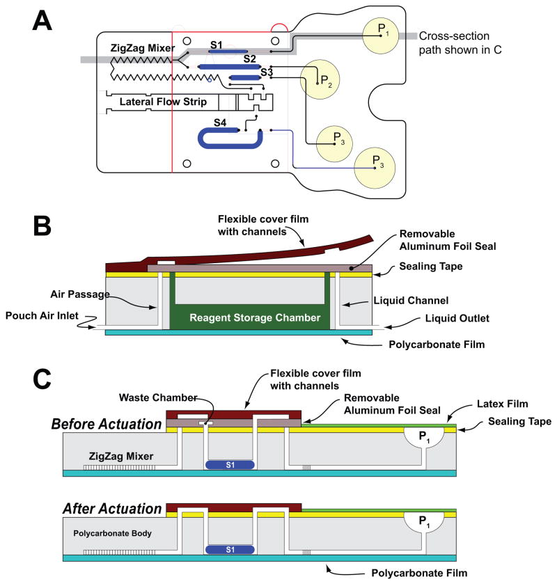
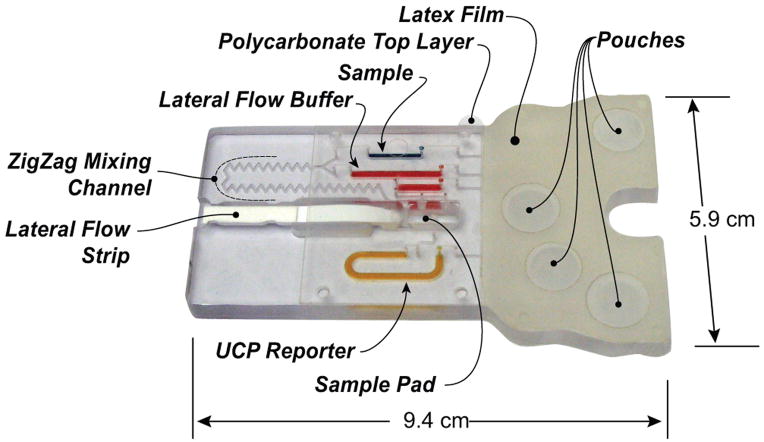
The cassette is depicted schematically in Fig. 1. Fig. 1A, 1B, and 1C are, respectively, a top view of the cassette; cross-section along the width of the cassette in its storage (pre-activation) state; and the cross-sections (shown in 1A) along the length of the cassette prior (top) and after (bottom) the cassette activation. Fig. 2 is a photograph of the assembled cassette in its actuated mode. In Fig. 2, the various storage chambers are shown filled with dyes for better visibility.
Fig. 1.
A schematic depiction of the polycarbonate fluidic chip consisting of air pouches (P1–P4), a metering chamber (S1), reagents storage chambers (S2–S4), a zigzag mixer, and a lateral flow (LF) strip. (A) top view; (B) cross-section along the width of the cassette in its storage (pre-activation) state; (C) cross-sections along the length of the cassette prior (top) and after (bottom) the cassette activation.
Fig. 2.
A photograph of the assembled immunoassay cassette that consists of latex rubber film, flexible polymer film with connecting conduits, double-sided tape, lateral flow strip, stored reagents, and sample. For better visibility, the various storage chambers are filled with dyes (blue=sample; red=LF buffer; orange= UCP reporter buffer)
The body of the cassette consists of a 94mm long ×58mm wide, 5.84mm thick polycarbonate (PC) sheet (Fig. 1A). To fabricate prototypes, we used a computer-controlled (CNC) milling machine (HAAS Automation Inc., Oxnard, CA). In quantity production, the cassettes will be formed with injection molding. The top surface of the PC contains wells for the air pouches (denoted P1-P4 in Fig 1A), access ports for the vertical vias, and the lateral flow strip chamber (see the Electronic Supplemental Information (ESI), Fig. S1A). The bottom surface of the polycarbonate sheet contains the air and liquid conduits (Figs. 1B and 1C), the sample metering chamber (S1), the reagent storage chambers (S2–S4), and the zigzag mixing channel (see ESI, Fig. S1B). The conduits have square cross-sections with widths and depths ranging from 250μm to 500μm, and the storage chambers have vaulting cross-sections with 1.6mm widths and 1.6mm depths. The chambers formed in the bottom layer are connected to the top surface with 500μm diameter vertical vias. The conduits in the bottom layer are capped with a 120μm thick polycarbonate film (Figs. 1B and 1C) that is thermally bonded to the polycarbonate sheet. The air pouch wells (P1–P4) are capped with a 100μm thick, flexible, natural latex rubber film (McMaster-Carr, New Brunswick, NJ) that is attached to the polycarbonate with the aid of double-sided adhesive tape (McMaster-Carr, New Brunswick, NJ).
During storage (Fig. 1B and 1C, top), all the chambers, with the exception of the metering chamber, are hermetically sealed with the sealing film located on the top surface of the polycarbonate sheet. The sealing film allows sample introduction into the metering chamber (S1) and the flow of excess sample into the waste chamber (Figs. 1C). The waste chamber is located within the sealing layer. Chambers S2, S3, and S4 store the various reagents needed to carry out the immunoassay and are pre-filled during the cassette manufacturing phase. Chamber S2 is the lateral flow buffer storage chamber. Chamber S3 is the wash solution storage chamber. Chamber S4 is the labels’ solution storage chamber.
Subsequent to the sample introduction, the sealing layer is peeled off and replaced with a connecting cover film (Fig. 1C, bottom). The connecting cover film is made of polymer film in which conduits have been machined with a CO2 laser. The flexible connecting cover is permanently attached to the PC cassette to assure appropriate alignment of the connecting conduits with the various openings. Once attached to the double sided tape affixed to the polycarbonate sheet, the conduits in the cover film form connections between the air conduit ends and the chamber inlets and between the chambers’ exits and the downstream conduits leading to the lateral flow strip.
The cassette consists of four functional regions: (i) the pumping region containing the air pouches, (ii) the storage and metering chambers region, (iii) the stirrer, and (iv) the immunochromatography zone, which includes the lateral flow strip.
The sample is processed following the consecutive flow protocol, which was developed for the multiplex detection of antibodies to infectious diseases such as HIV, HCV, and TB with an antibody-generic reporter label.52 After the sample is loaded onto the cassette, pouches P1 and P2 are compressed simultaneously by the actuator. The air from pouches P1 and P2 displace, respectively, the sample and the lateral flow buffer into the zigzag channel, where the sample mixes with the lateral flow buffer. Subsequently, the sample-buffer blend is discharged onto the lateral flow strip’s sample pad. The liquids migrate up the strip by capillary forces. The strip includes test zones with immobilized ligands that bind specifically to the target analytes in the sample and a control zone that binds the labels that were not captured in the test zone.
After a predetermined time interval (2min), pouch P3 is compressed to discharge the wash solution onto the sample pad to remove any unbound analytes. Two minutes later, pouch P4 is compressed to discharge the buffer containing the functionalized UCP reporter particles onto the sample pad. Although for the studies reported herein upconverting phosphor particles were employed as the reporter particles, the cassette can utilize any other functionalized labels such as gold particles (which facilitate visual detection), quantum dots, and fluorophores.
The timer-actuator
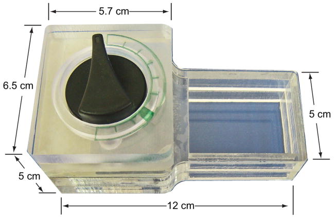
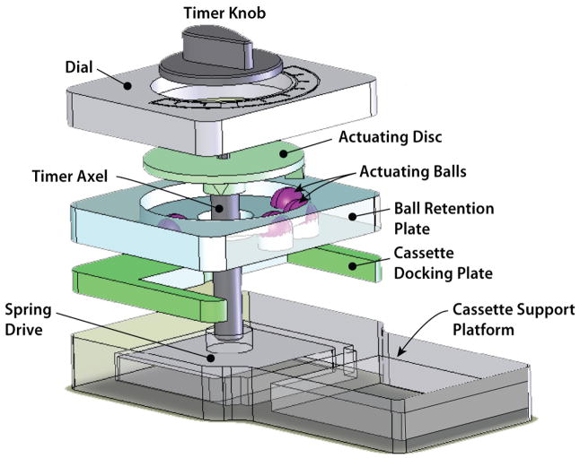
Figs. 3 and 4 show a photograph and a three-dimensional exploded view of the actuation mechanism. The actuation mechanism consists of a dial, an actuating disc, a ball-holding plate (cage), a cassette socket, cassette platform, and a spring-driven actuator-timer with a 15min time span (McMaster-Carr, New Brunswick, NJ). The rotating, actuating disc, with two triangular protrusions of 5mm length × 6mm width × 3.7mm height positioned 82.28o apart, is fixed to the rotating shaft (ESI, Fig. S2). The actuating protrusions on the disc rotate with the shaft and press the caged balls (ESI, Fig. S3) at predetermined times. The ball-holding plate has four 9.6mm diameter holes in which four actuating plastic balls with diameters of 9.5mm were caged. By adjusting the inclination angles of the protrusions, one can adjust the flow rates of the reagents. Once the air pouch has been compressed, the air displaces the liquid from the storage compartment and forces it to flow downstream.
Fig. 3.
A photograph of the hand-held, timer-based actuator
Fig. 4.
An exploded view of the actuating mechanism of the timer-based actuator. After the knob is turned clockwise to a preset position and the timer is set, the self-contained immunoassay cassette is inserted into the cassette bay of the actuator and the actuating disc rotates counter-clockwise. The protrusions of the rotating disc deform the flexible films of the air pouches and discharge the air to displace the sample and various reagents in a timely fashion.
Subsequent to the sample loading, the timer is initialized (by positioning the timer’s knob at a prescribed position) and the cassette is docked in the timer-actuator so that it is aligned with the air pouches beneath the actuating balls (Fig. 4 and ESI, Fig. S4). The LF immunoassay protocol requires moving sample volumes of 10μL and a LF buffer of 40μL. To accommodate these different volumes, the system utilizes different size air pouches for the sample and the lateral flow buffer.
Once the cassette has been inserted into the docking chamber, the timer rotates the actuating disk with the protrusions. Initially, both protrusions press simultaneously on pouches P1 and P2 (Fig. 1A and ESI, Fig. S4B) to facilitate the concurrent flow of the sample (S1) and buffer (S2) into the zig-zag mixer. Subsequently, after a predetermined time interval (of 2 min), one of the protrusions actuates pouch P3 and 2 min later pouch P4.
3. Stirrer
Since turbulent flows are difficult to generate in microfluidic systems with conduit sizes on the order of hundreds of micrometers, it is necessary to induce secondary flows to enhance mixing. In current microfluidic devices, passive mixers, which take advantage of the microchannels’ geometry, are often used due to their ease of integration.53–55 Here, we rely on a zigzag channel mixer, in which the sample and lateral flow buffer flow concurrently. In addition to providing a long path to accommodate the diffusion process, the bends in the conduit induce secondary flows that enhance mixing.
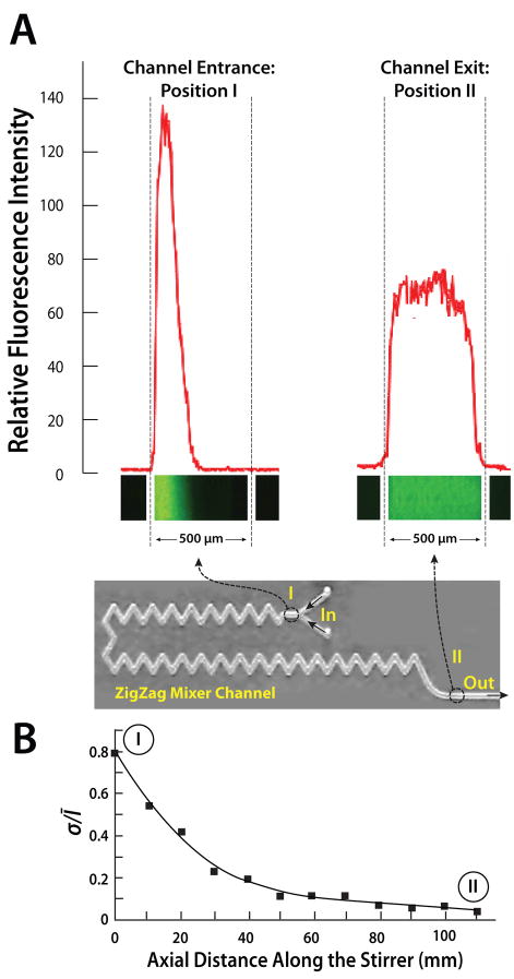
To evaluate the stirrer’s performance, rhodamine 123 fluorescence dye in LF buffer solution was used to mimic the sample. A fluorescence microscope was used to record the mixing process. Figs. 5A shows the fluorescence images and the fluorescent relative intensity as functions of position along the conduit’s width at the inlet (I) and exit (II) regions. At the inlet, the dye occupies only part of the conduit’s width and the two solutions are well separated with a nearly sharp interface. In contrast, at the exit (II) the dye is spread nearly evenly across the conduit’s width, indicating good mixing.
Fig. 5.
A photograph of the zigzag mixer in the cassette combined with images of the fluorescent intensities at the stirrer’s inlet (I) and exit (II) as a function of the conduit’s width (A). The fluorescent images were captured with a CCD camera. The Reynolds number of the flow (based on the hydraulic diameter) is 5. (B) The standard deviation of the fluorescence intensity, normalized with the average intensity, is depicted as a function of the conduit’s length.
To quantify the mixing process, we define the standard deviation
of the dye’s intensity. In the above, Ī is the average of the dye’s intensity across the conduit’s width. When the two component liquids are well-separated, σ will approach 1. For example, when the dye occupies half of the conduit’s width at uniform intensity, σ ~ 0.71Ī. When the two fluids are well mixed and the dye intensity is nearly uniform across the conduit’s width, σ →0. Fig. 5B depicts the normalized standard deviation σ/Ī as a function of the axial distance along the stirrer’s length when the Reynolds number (based on the conduit’s hydraulic diameter) is 5. Witness that σ/Ī decreases rapidly and asymptotically approaches the value of zero, confirming that the zigzag stirrer provides effective mixing.
4. Reagents and protocols
In our experiments, we tested two different analytes HIV antibodies and 305-bp DNA amplicon labeled with 5′-Digoxigenin and 5′-Biotin. The HIV antibodies were spiked into saliva, and the DNA fragments were suspended in water. The former was used to demonstrate the ability of the cassette to detect the presence of HIV antibodies in saliva. The latter enabled us to carry out a dilution series to obtain quantitative performance data. In both cases, the protocol consisted of three consecutive flow steps: (i) a 10μL sample (saliva or PCR amplicons suspended in water) was mixed with a 40μL LF buffer, then applied to the lateral flow strip; (ii) after two minutes, 20μL LF buffer was blotted onto the sample pad to remove any unbound analytes; and (iii) two minutes later, 80μL LF buffer with 100ng UCP conjugate was transferred to the LF strip. 15 minutes was allowed to complete the immunochromatography before strips were removed and analyzed with a reader.
The OraQuick ADVANCE Rapid HIV-1/2 Antibody Test Kit Control sera spiked into saliva generated the negative and low positive HIV samples. The high HIV positive sample was formulated by spiking serum from a Women’s Interagency HIV Study (WIHS) subject with a high viral load into saliva.
The lateral flow buffer consisted of 100 mM Hepes (pH 7.2), 270 mM NaCl, 0.5% (v/v) Tween-20, and 1% (w/v) BSA (Sigma #A7030). The immunolabeling buffer was a mixture LF buffer with protein A–coated UCP (UCP-Protein A) reporter particles for anti-HIV antibodies and mouse anti-dig antibodies-conjugated UCP reporter particles for haptenized DNA.
LF strips (OraSure Technologies, Inc., Bethlehem, PA) consist of a 4 mm × 20mm nitrocellulose strip (SRHF04000, Millipore, Billerica, MA) with a 4 mm X 10mm sample loading pad (glass-fiber No. 33, Schleicher & Schuell) at the upstream end and a 4 mm × 20mm absorbent waste pad (paper No. 470, Schleicher & Schuell) on the downstream end. The HIV LF strip test-line contains immobilized synthetic peptides to glycoproteins of the HIV envelope and a control line of immobilized goat anti-human IgG to verify the successful migration of the UCP-protein-A labels up the strip. The DNA capture LF strips contained a test line of avidin-D and a control line of goat anti-mouse IgG antibody. See ESI, Fig. S5B.
The DNA samples were produced by lysing B. cereus cells, isolating the DNA with QIAGEN DNeasy™ Tissue Kit (QIAGEN Inc., Valencia, CA 91355), and using the eluted DNA as the PCR template. The PCR reagents were 50mM Tris-HCl (pH 9.0), 1.5–3.5mM MgCl2, 200μM dNTP, and 0.1μg/μL BSA. The forward and reverse primers used at 0.3μM were, respectively, 5′Biotin-TCT CGC TTC ACT ATT CCC AAG T-3′ and 5′Digoxigenin-AAG GTT CAA AAG ATG GTA TTC AGG-3′. The primers targeted a 305bp specific gene fragment.1 The DNA amplification was initiated with a denaturation step at 95°C for 120sec, followed by 25 amplification cycles (95°C, 20sec; 55°C, 30sec; 72°C, 23sec), and terminated with an extension step at 72°C for another 120sec on a PCR thermocycler (Techne Incorporated, Princeton, NJ). The haptenized DNA concentration of the initial PCR products was determined using a NanoDrop ND-1000 spectrophotometer (NanoDrop Technologies, Wilmington, DE). A UCP Reader (UPlink, Orasure Technologies, Inc., Bethlehem, PA) was used to read the DNA strips (See ESI, Fig. S5B).
5. Results and discussion
Cassette operation
The sample spiked with anti-HIV antibodies or haptenized DNA was inserted into the metering chamber. Any excess sample was discharged into the waste chamber located in the sealing film (Fig. 1C). Next, the sealing film was peeled off. Then the flexible cover film was affixed onto the double-sided tape to join the air pouches with the storage chambers on the one hand and the storage chambers with the lateral flow strip on the other hand. Since the flexible cover film’s position was predetermined through the attachment of its edge to the PC cassette, good sealing and alignment were assured. Finally, the cassette was inserted into the timer-based actuator for sample mixing and reagent pumping. Once the cassette was inserted in the actuator, the operation proceeded in a fully automated fashion.
Actuation mechanism of timer-based actuator
The cassette was actuated with the timer-actuator (having a maximum time interval of 15min and maximum displacement angle of 308.55o). To realize mixing, two protruding bars of the actuating disc pressed the two balls that, in turn, compressed the air pouches of the sample chamber and buffer chamber to simultaneously discharge the sample and buffer into the zigzag channel for online mixing. The displacement angles of the other two balls were 41.14o each, corresponding to time intervals of 2min (see ESI, Fig. S3).
The operation of the actuator is illustrated in Fig. 4 and ESI, Fig. S4. At the beginning of the operation, the protrusions were displaced away from the actuating balls (Fig. 4A). The timer rotated the actuating disk counter-clockwise and brought the two protrusions into contact with the two balls that actuated, respectively, the air pouch associated with the metering chamber and the air pouch associated with the lateral flow buffer chamber (ESI, Fig. S4B). The sample was mixed with the lateral flow buffer in the zigzag channel and pumped into the strip’s chamber. Two minutes later, the actuating protrusion moved on top of the ball that actuated the air pouch associated with the wash buffer chamber, and pressed it down. As a result, the wash LF buffer was discharged into the strip’s chamber. Two minutes later, the actuating protrusion pressed the last ball that actuated the air pouch associated with the UCP storage buffer chamber, and the UCP suspension was discharged into the strip’s chamber. Here, our timer-based actuator had two major functions: one was to automate the timing and the other was to actuate the air pouches to pump the sample and reagents into the strip chamber. A movie illustrating the cassette’s operation is available on the web as supplementary information.
Dead volumes
To estimate the dead volumes, we weighed cassettes filled with one reagent at a time (without a lateral flow strip) and empty cassettes (after the removal of the lateral flow strip). The lost volumes of the saliva sample-buffer mixture, wash buffer, and UCP-conjugate buffer were, respectively, smaller than 4.7%, 2.0% and 2.7%. Not surprisingly, due to the long zigzag mixing channel, the sample-buffer mixture had the largest dead volume.
HIV Immunoassay
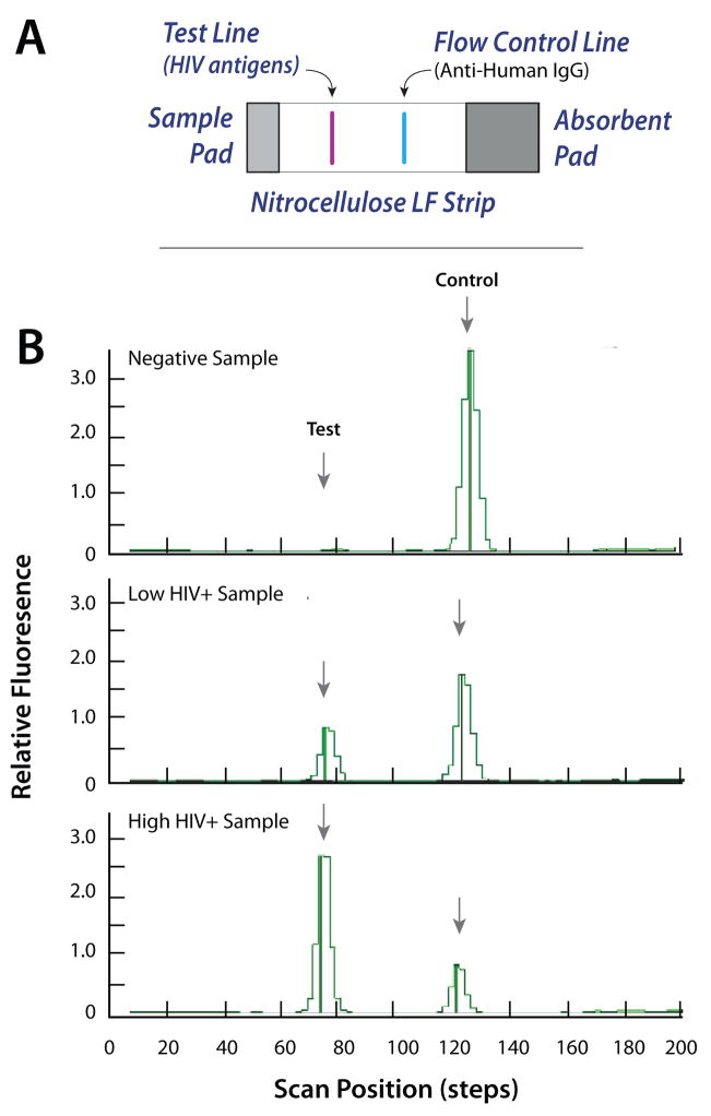
Fig. 6 depicts a representative result of the HIV antibody detection test. The lateral flow strip includes a test line consisting of HIV-specific antigens and a control line functionalized with anti-human IgG to bind protein A functionalized to the UCP labels (see ESI, Fig. S5A). Three groups of samples: negative, low positive, and high positive HIV Sera in saliva were tested. After incubation, the LF strip was removed from the cassette and then inserted into a standard Packard Reader. (In the future, a much smaller reader will be integrated with the actuator). Fig. 6B depicts the fluorescence intensity of the negative, low positive, and high positive HIV samples in relative fluorescent units (RFU) as a function of the position along the strip. The areas under the peaks are proportional to the amount of target analyte(s). The negative signal yielded no test peak and a large control peak. The low positive sample yielded moderate height test and control peaks. The high positive sample yielded a high test peak and a low control peak. The tests were repeated numerous times with similar results.
Fig. 6.
(A) the lateral flow strip consists of a sample pad, a nitrocellulose membrane, and an adsorbent pad. The nitrocellulose strip is equipped with a test line and a control line. (B) Emission profiles (scan results) of negative, low positive, and high positive HIV samples. The signals (in relative fluorescent units) are depicted as functions of position along the strip.
Fig. 7 depicts the ratio (T/C) of the areas of the test (T) and the control (C) signals. As the HIV antibodies concentration increased, so did the ratio T/C. Each bar represents the average of measurements with three different cassettes. The range of the data is indicated with the error bars.
Fig. 7.
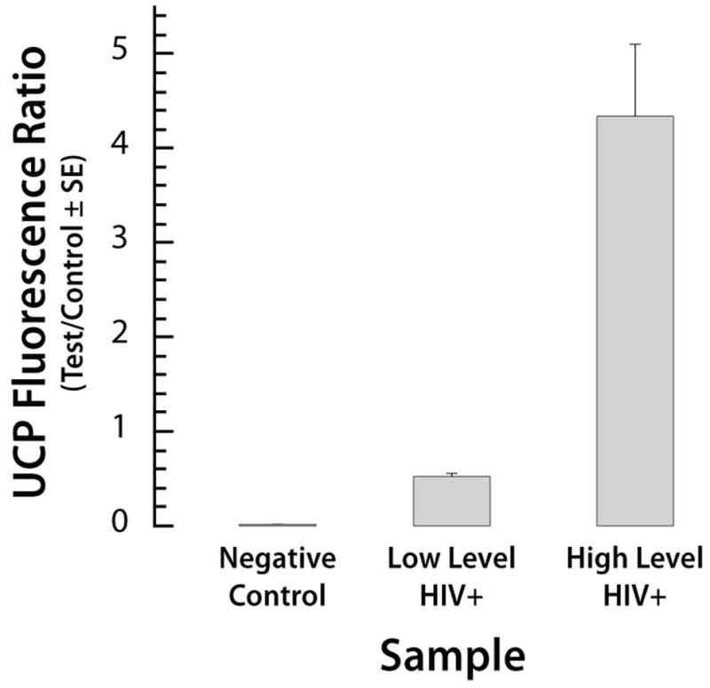
The ratio of the test and the control signals for the HIV test using negative, low positive, and high positive samples. The signals correspond to the areas under the peaks. The error bars correspond to the scatter of the data obtained with three cassettes.
Labeled 305 bp DNA
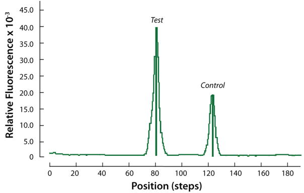
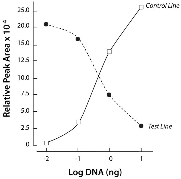
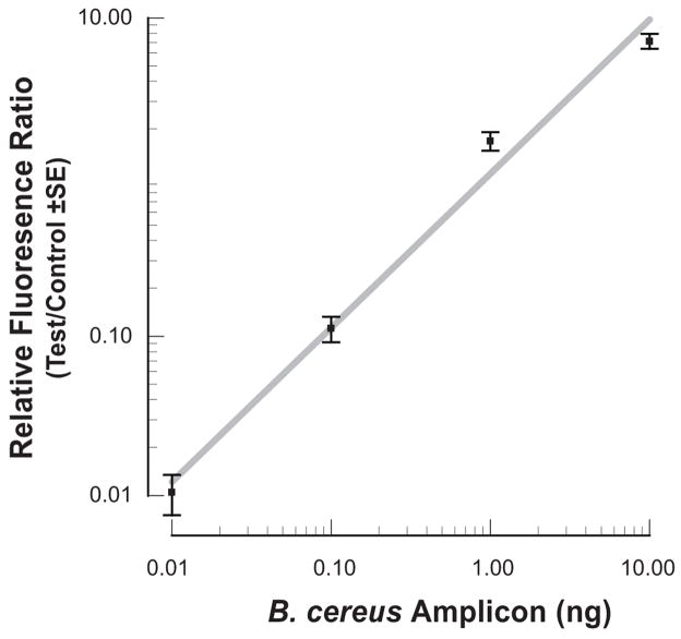
Since quantitative information on the concentrations of the HIV antibodies in the HIV samples is not available, to obtain quantitative data, we constructed target analyte consisting of haptenized DNAmolecules functionalized with biotin and digoxigenin (Dig). The sole role of the DNA is to serve as a linker between the digoxigenin and the biotin. The lateral flow strip contained a test line of avidin-D and a control line of goat anti-mouse IgG antibody (see ESI, Fig. S5B). Test samples contained 0, 0.01ng, 0.1ng, 1ng, and 10ng of a digoxigenin and biotin labeled 305bp B. cereus DNA amplicon in 10 μl of water. Fig. 8 depicts a representative example of the test and control peaks for the sample containing 1ng of DNA. Fig. 9 depicts the areas of the test (diamonds) and control (upright triangles) peaks as functions of the DNA concentration (W). As the DNA concentration increased, the area of the test peak increased and the area of the control peak decreased. Fig. 10 depicts the ratio of the test and control peak’s areas (T/C) (after subtracting the ratio for the negative sample) as a function of the DNA concentration. The relative ratio of the control and test signals correlates well with the curve (a x)α (solid line). In the above, a=1.05(ng)−1, α~0.97, and x is the DNA mass in ng. Each data point is the average of experiments carried out with three different cassettes. The scatter (range) of the data is represented with the error bars. The Signal/Noise ratio of the test peak of the DNA at 0.01ng was above 10 (not shown). Unfortunately, negative tests occasionally produced a similar signal level as the 0.01ng samples. We speculate that the immobilization of the proteins to form the test region may have modified slightly the properties of the lateral flow strip, causing nonspecific trapping of label particles and leading to a small peak. Based on a limited number of experiments, we tentatively conclude that the system is capable of reliably detecting less than 0.1ng (~0.5 femtomol) of target analyte.
Fig. 8.
Emission profile (scan result) of 1ng haptenized DNA sample. The scan signal is depicted as a function of position along the strip.
Fig. 9.
The test (T, solid diamonds) and control (C, upright, solid triangles) signals’ areas are depicted as a function of the DNA concentration (ng).
Fig. 10.
The ratio of the test and the control signal areas of the haptenized PCR amplification as a function of DNA concentration. The error bars represent the scatter of data obtained with three cassettes.
6. Conclusions and Outlook
An easy-to-use, self-contained, inexpensive, disposable immunoassay cassette was developed and successfully tested. The cassette integrates reagent storage, sample metering, mixing, pumping, and a lateral flow immunochromatography strip. A novel method was introduced to facilitate simple interconnecting of the storage chambers with the upstream air pouches and the downstream processing. In contrast to other currently available tests, the system operates in an automatic fashion and does not require trained personnel. Although the device described herein operated with a lateral flow strip as the ligand immobilization matrix, with modifications, the cassette can accommodate other biofunctionalized immobilization substrates such as beads and patterned plastics. UCP was used in this study as the reporter. The cassette can employ, however, other labels such as gold particles, quantum dots, and fluorophores. Furthermore, other detection modalities such as electrochemical detection could be used as well.
The blending of the sample and buffer was accomplished with a zigzag stirrer, which provided adequate performance. Other passive stirrer geometries can be implemented as well. In fact, we constructed three-dimensional, bend-based stirrers of the type analyzed in Yi et al.56, but we do not report their performance characteristics here.
A hand-held timer-based actuator was designed and fabricated to automate the actuation of the air pouches and to facilitate timely pumping of the sample and the stored reagents in a predetermined sequence such as dictated by consecutive flow, immunoassay protocol. Although not implemented here, if desired, the timer-actuator can be integrated into the cassette to form a disposable, single-use system. The timer actuator could be replaced with a stepping motor for applications that require a larger number of and more complicated processing steps than the ones required for the present application. Furthermore, in the future, a miniature laser diode/photo diode reader will be integrated with the actuator to form a fully integrated hand-held device.
The device’s performance was demonstrated with the detection of host antibodies to the HIV virus and the detection of haptenized DNA fragments of B. cereus. With appropriate immobilized ligands, the device can be used for the detection of a variety of other samples derived from body fluids, water, and food. Due to its simplicity and projected low cost, the device is particularly suitable for resource-poor regions.
Supplementary Material
Acknowledgments
The work was supported by NIH/NIDCR Grant U01DE017855, by the University of Pennsylvania Institute for Translational Medicine and Therapeutics (ITMAT), and by the New York State Foundation for Science, Technology, and Innovation. Some of the samples used in this study were collected by the Women’s Interagency HIV Study (WIHS) and its associated Collaborative Study Groups.
References
- 1.Wang J, Chen Z, Corstjens PLAM, Mauk MG, Bau HH. Lab Chip. 2006;6:46–53. doi: 10.1039/b511494b. [DOI] [PubMed] [Google Scholar]
- 2.Srinivasan V, Pamula VK, Fair RB. Lab Chip. 2004;4:310–315. doi: 10.1039/b403341h. [DOI] [PubMed] [Google Scholar]
- 3.Yager P, Edwards T, Fu E, Helton K, Nelson K, Tam MR, Weigl BH. Nature. 2006;442:412–418. doi: 10.1038/nature05064. [DOI] [PubMed] [Google Scholar]
- 4.Chen X, Cui D, Liu C. Electrophoresis. 2008;29:1844–1851. doi: 10.1002/elps.200700551. [DOI] [PubMed] [Google Scholar]
- 5.Garcia E, Kirkham JR, Hatch AV, Hawkins KR, Yager P. Lab Chip. 2004;4:78–82. doi: 10.1039/b308914b. [DOI] [PubMed] [Google Scholar]
- 6.Linder V, Verpoorte E, de Rooij NF, Sigrist H, Thormann W. Electrophoresis. 2002;23:740–749. doi: 10.1002/1522-2683(200203)23:5<740::AID-ELPS740>3.0.CO;2-7. [DOI] [PubMed] [Google Scholar]
- 7.Phillips KS, Cheng Q. Anal Chem. 2005;77:327–334. doi: 10.1021/ac049356+. [DOI] [PubMed] [Google Scholar]
- 8.Herrmann M, Roy E, Veres T, Tabrizian M. Lab Chip. 2007;7:1546–1552. doi: 10.1039/b707883h. [DOI] [PubMed] [Google Scholar]
- 9.Sia SK, Linder V, Parviz BA, Siegel A, Whitesides GM. Angew Chem Int Ed. 2004;43:498–502. doi: 10.1002/anie.200353016. [DOI] [PubMed] [Google Scholar]
- 10.Linder V, Sia SK, Whitesides GM. Anal Chem. 2005;77:64–71. doi: 10.1021/ac049071x. [DOI] [PubMed] [Google Scholar]
- 11.Lucas LJ, Chesler JN, Yoon JY. Biosens Bioelectron. 2007;23:675–681. doi: 10.1016/j.bios.2007.08.004. [DOI] [PubMed] [Google Scholar]
- 12.Yu F, Persson B, Lofas S, Knoll W. Anal Chem. 2004;76:6765–6770. doi: 10.1021/ac048937w. [DOI] [PubMed] [Google Scholar]
- 13.Luo Y, Yu F, Zare RN. Lab Chip. 2008;8:694–700. doi: 10.1039/b800606g. [DOI] [PubMed] [Google Scholar]
- 14.Kurita R, Yokota Y, Sato Y, Mizutani F, Niwa O. Anal Chem. 2006;78:5525–5531. doi: 10.1021/ac060480y. [DOI] [PubMed] [Google Scholar]
- 15.Cesaro-Tadic S, Dernick G, Juncker D, Buurman G, Kropshofer H, Michel B, Fattinger C, Delamarche E. Lab Chip. 2004;4:563–569. doi: 10.1039/b408964b. [DOI] [PubMed] [Google Scholar]
- 16.Smits HL, Eapen CK, Sugathan S, Kuriakose M, Gasem MH, Yersin C, Sasaki D, Pujianto B, Vestering M, Abdoel TH, Gussenhoven GC. Clin Diagn Lab Immunol. 2001;8:166–169. doi: 10.1128/CDLI.8.1.166-169.2001. [DOI] [PMC free article] [PubMed] [Google Scholar]
- 17.Johnston SP, Ballard MM, Beach MJ, Causer L, Wilkins PP. J Clin Microbiol. 2003;41:623–626. doi: 10.1128/JCM.41.2.623-626.2003. [DOI] [PMC free article] [PubMed] [Google Scholar]
- 18.Corstjens PLAM, Lieshout LV, Zuiderwijk M, Kornelis D, Tanke HJ, Deelder AM, Dam GJV. J Clin Microbiol. 2008;24:171–176. doi: 10.1128/JCM.00877-07. [DOI] [PMC free article] [PubMed] [Google Scholar]
- 19.Salomone A, Roggero P. J Plant Pathol. 2002;84:65–68. [Google Scholar]
- 20.Park SJ, Taton TA, Mirkin CA. Science. 2002;295:1503–1506. doi: 10.1126/science.1067003. [DOI] [PubMed] [Google Scholar]
- 21.Chan WCW, Nie SM. Science. 1998;281:2016–2018. doi: 10.1126/science.281.5385.2016. [DOI] [PubMed] [Google Scholar]
- 22.van de Rijke F, Zijlmans H, Li S, Vail T, Raap AK, Niedbala RS, Tanke HJ. Nat Biotechnol. 2001;19:273–276. doi: 10.1038/85734. [DOI] [PubMed] [Google Scholar]
- 23.Zijlmans HJ, Bonnet J, Burton J, Kardos K, Vail T, Niedbala RS, Tanke HJ. Anal Biochem. 1999;267:30–36. doi: 10.1006/abio.1998.2965. [DOI] [PubMed] [Google Scholar]
- 24.Hampl J, Hall M, Mufti NA, Yao YM, MacQueen DB, Wright WH, Cooper DE. Anal Biochem. 2001;288:176–187. doi: 10.1006/abio.2000.4902. [DOI] [PubMed] [Google Scholar]
- 25.Kuningas K, Ukonaho T, Pakkila H, Rantanen T, Rosenberg J, Lovgren T, Soukka T. Anal Chem. 2006;78:4690–4696. doi: 10.1021/ac0603983. [DOI] [PubMed] [Google Scholar]
- 26.Mokkapati VK, Niedbala RS, Kardos K, Perez RJ, Guo M, Tanke HJ, Corstjens PLAM. Ann N Y Acad Sci. 2007;1098:476–485. doi: 10.1196/annals.1384.021. [DOI] [PubMed] [Google Scholar]
- 27.Yan ZQ, Zhou L, Zhao YK, Wang J, Huang LH, Hu KX, Liu HH, Wang H, Guo ZB, Song YJ, Huang HJ, Yang RF. Sens Actuators B. 2006;119:656–663. doi: 10.1016/j.snb.2006.01.029. [DOI] [PMC free article] [PubMed] [Google Scholar]
- 28.Zuiderwijk M, Tanke HJ, Niedbala RS, Corstjens PLAM. Clin Biochem. 2003;36:401–403. doi: 10.1016/s0009-9120(03)00057-2. [DOI] [PubMed] [Google Scholar]
- 29.Corstjens PLAM, Zuiderwijk M, Nilsson M, Feindt H, Niedbala RS, Tanke HJ. Analytical Biochemistry. 2003;312:191–200. doi: 10.1016/s0003-2697(02)00505-5. [DOI] [PubMed] [Google Scholar]
- 30.Streckfus CF, Bigler LR. Oral Dis. 2002;8:69–76. doi: 10.1034/j.1601-0825.2002.1o834.x. [DOI] [PubMed] [Google Scholar]
- 31.Segal A, Wong DT. Eur J Dent Educ. 2008;12:22–29. doi: 10.1111/j.1600-0579.2007.00477.x. [DOI] [PMC free article] [PubMed] [Google Scholar]
- 32.Herr AE, Hatch AV, Throckmorton DJ, Tran HM, Brennan JS, Giannobile WV, Singh AK. Proc Natl Acad Sci USA. 2007;104:5268–5273. doi: 10.1073/pnas.0607254104. [DOI] [PMC free article] [PubMed] [Google Scholar]
- 33.Malamud D, Bau HH, Niedbala S, Corstjens P. Adv Dent Res. 2005;18:12–16. doi: 10.1177/154407370501800104. [DOI] [PubMed] [Google Scholar]
- 34.Chen Z, Mauk MG, Wang J, Abrams WR, Corstjens PLAM, Niedbala RS, Malamud D, Bau HH. Ann N Y Acad Sci. 2007;1098:429–436. doi: 10.1196/annals.1384.024. [DOI] [PubMed] [Google Scholar]
- 35.Ferguson DB. J Dent Res. 1987;66:420–424. doi: 10.1177/00220345870660020601. [DOI] [PubMed] [Google Scholar]
- 36.Mandel ID. J Oral Pathol Med. 1990;19:119–125. doi: 10.1111/j.1600-0714.1990.tb00809.x. [DOI] [PubMed] [Google Scholar]
- 37.Malamud D. Br Med J. 1992;305:207–208. doi: 10.1136/bmj.305.6847.207. [DOI] [PMC free article] [PubMed] [Google Scholar]
- 38.Ziober BL, Mauk MG, Falls EM, Chen Z, Ziober AF, Bau HH. Head Neck. 2008;30:111–121. doi: 10.1002/hed.20680. [DOI] [PubMed] [Google Scholar]
- 39.Liu C, Cui D, Chen X. Journal of Chromatography A. 2007;1170:101–106. doi: 10.1016/j.chroma.2007.08.087. [DOI] [PubMed] [Google Scholar]
- 40.Dodge A, Fluri K, Verpoorte E, de Rooij NF. Anal Chem. 2001;73:3400–3409. doi: 10.1021/ac0015366. [DOI] [PubMed] [Google Scholar]
- 41.Sato K, Yamanaka M, Hagino T, Tokeshi M, Kimura H, Kitamori T. Lab Chip. 2004;4:570–575. doi: 10.1039/b411356j. [DOI] [PubMed] [Google Scholar]
- 42.Eteshola E, Leckband D. Sens Actuators B. 2001;72:129–133. [Google Scholar]
- 43.Yakovleva J, Davidsson R, Lobanova A, Bengtsson M, Eremin S, Laurell T, Emneus J. Anal Chem. 2002;74:2994–3004. doi: 10.1021/ac015645b. [DOI] [PubMed] [Google Scholar]
- 44.Jiang X, Ng JMK, Stroock AD, Dertinger SKW, Whitesides GM. J Am Chem Soc. 2003;125:5294–5295. doi: 10.1021/ja034566+. [DOI] [PubMed] [Google Scholar]
- 45.Malmstadt N, Hoffman AS, Stayton PS. Lab Chip. 2004;4:412–415. doi: 10.1039/b315394k. [DOI] [PubMed] [Google Scholar]
- 46.Murakami Y, Endo T, Yamamura S, Nagatani N, Takamura Y, Tamiya E. Anal Biochem. 2004;334:111–116. doi: 10.1016/j.ab.2004.07.029. [DOI] [PubMed] [Google Scholar]
- 47.Chen X, Cui D, Liu C, Li H. J Micromech Microeng. 2007;17:68–75. [Google Scholar]
- 48.Lai S, Wang S, Luo J, Lee LJ, Yang ST, Madou MJ. Anal Chem. 2004;76:1832–1837. doi: 10.1021/ac0348322. [DOI] [PubMed] [Google Scholar]
- 49.Morier P, Vollet C, Michel PE, Reymond F, Rossier JS. Electrophoresis. 2004;25:3761–3768. doi: 10.1002/elps.200406093. [DOI] [PubMed] [Google Scholar]
- 50.Hosokawa K, Omata M, Sato K, Maeda M. Lab Chip. 2006;6:236–241. doi: 10.1039/b513424b. [DOI] [PubMed] [Google Scholar]
- 51.Liu RH, Munro SB, Nguyen T, Siuda T, Suciu D, Bizak M, Slota M, Fuji HS, Danley D, McShea A. J Assoc Lab Autom. 2006;11:360–367. [Google Scholar]
- 52.Corstjens PLAM, Chen Z, Zuiderwijk M, Bau HH, Abrams WR, Malamud D, Niedbala RS, Tanke HJ. Ann N Y Acad Sci. 2007;1098:437–445. doi: 10.1196/annals.1384.016. [DOI] [PubMed] [Google Scholar]
- 53.Mengeaud V, Josserand J, Girault HH. Anal Chem. 2002;74:4279–4286. doi: 10.1021/ac025642e. [DOI] [PubMed] [Google Scholar]
- 54.Liu A, He F, Wang K, Zhou T, Lu Y, Xia X. Lab Chip. 2005;5:974–978. doi: 10.1039/b502764k. [DOI] [PubMed] [Google Scholar]
- 55.Chen X, Cui DF, Liu CC, Li H. Sens Actuators B. 2008;130:216–221. [Google Scholar]
- 56.Yi M, Bau HH. International Journal of Heat and Fluid Flow. 2003;24:645–656. [Google Scholar]
Associated Data
This section collects any data citations, data availability statements, or supplementary materials included in this article.


