Abstract
A microfabricated magnetic sifter has been designed and fabricated for applications in biological sample preparation. The device enables high-throughput, high-gradient magnetic separation of magnetic nanoparticles by utilizing columnar fluid flow through a dense array (~5000/mm2) of micropatterned slots in a magnetically soft membrane. The potential of the sifter for separation of magnetic nanoparticles conjugated with capture antibodies is demonstrated through quantitative separation experiments with CD138-labelled MACS nanoparticles. Capture efficiencies ranging from 28–37% and elution efficiencies greater than 73% were measured for a single pass through the sifter.
Keywords: magnetic sifter, high-gradient magnetic separation, magnetic nanoparticles, cell separation, CD138, microfluidics
Magnetic separation is emerging as an important sample preparation tool in biology and medicine. Recently, magnetic nanoparticles conjugated with recognition moieties have been used to selectively isolate cells [1–2] and proteins [3–4]. Purification and pre-concentration of proteins, DNA, and cells can lower the detection threshold of bioassays, increase the throughput of sample preparation and flow cytometry, as well as facilitate biological studies on separated biomolecules and cells.
In its simplest form, magnetic separation can be achieved by placing a vial containing a previously incubated mixture of a biological sample and magnetic particles conjugated with capture probes in proximity to a permanent magnet. The magnetic particles and attached biological targets are pulled towards the magnet, and the remaining volume is aspirated and discarded. The magnetic particles and captured targets are then resuspended for subsequent analysis. The low field gradients generated by external magnets alone, however, generally result in long separation times or limit this approach to separating micron-scale magnetic beads. Furthermore, the required fluid handling steps render this approach undesirable for downstream processing or integration with “lab on a chip” systems.
More sophisticated magnetic separation devices allow for capture during continuous flow. These flow-through devices generally fall into one of two categories: macroscopic, columnar flow devices [5–6] or microfluidic, planar flow devices [7–8]. Each category has advantages and drawbacks.
Columnar flow devices typically consist of a large flow column or tube, ranging from millimeters to tens of centimeters in size, accompanied by an assembly of large external permanent magnets or electromagnets, which generate a non-uniform field to sequester the magnetic particles. These devices offer high flow rates but suffer from low field gradients due to the large dimensions of the device, so that capture requires analytes to be highly magnetic. A capture bed of soft magnetic material is often packed into the flow column to enhance local field gradients, but typically these beds have irregular structures and complex geometries which can result in non-uniform flow velocities and unintended target losses or damages, lowering the capture or elution efficiencies of the device. In addition, non-magnetic retention of unlabeled biomolecules and their subsequent release during forcible elutions can also be problematic, e.g., lowering the purity of separated molecules.
Microfluidic magnetic separation devices consist of flow channels with dimensions on the order of tens of microns and magnetic material or electromagnets patterned directly next to or inside the flow channel. These devices offer high magnetic field gradients due to the close proximity of the solution to the magnetic elements, predictable flow velocities, and minimal non-magnetic retention, but the small cross-sectional area and limited number of flow channels restricts throughput. A device that combines columnar flow with the high working magnetic field gradients found in microfluidic devices could offer both superior throughput and capture efficiencies in separating small, difficult-to-capture magnetic nanoparticles desired for many biological applications.
Here we report a novel design for a continuous flow-through magnetic separation device, the microfabricated magnetic sifter. The sifter is a 7 × 7 mm2 silicon die, containing a dense array of slots micromachined through a silicon nitride membrane. The slots, surrounded by a magnetically soft material, act as magnetic capture sites. Fig. 1 shows the separation principle of the sifter. A biological solution is incubated with magnetic nanoparticles functionalized with capture probes specific to a desired biological entity. The solution is pumped through the sifter during the application of an external magnetic field. The soft magnetic material surrounding the slots is magnetized by the external field, producing high local field gradients associated with the fringing fields at the slots. The magnetic nanoparticles and consequently the targets are captured by the field gradients. The remaining solution passes through the sifter. To release and collect the magnetic nanoparticles, the external field is removed, and water or a buffer solution is flushed through the device.
Fig. 1.
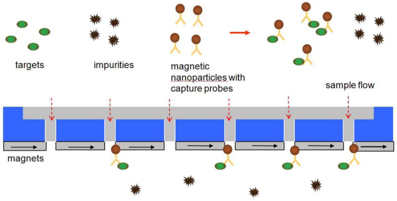
Capture principle of the magnetic sifter.
As with columnar flow devices, large volume fluid handling is achieved by parallel flow through a large number of slots, greater than 100,000 per die. Magnetic nanoparticles in solution are subjected to field gradients with magnitudes on the same order as those found in microfluidic devices, due to the direct placement of the magnetic material at the slot openings and the small width of the slots (4 μm).
Values for magnetic field gradients found in the sifter were obtained using an electromagnetic field simulation tool, Ansoft Maxwell 3D™, as well as calculated analytically using the expressions given in [9] for the magnetic field emitted by uniformly magnetized rectangular magnets. Values were calculated for 4 μm wide slots in a 2.6 μm thick cobalttantalum-zirconium (CoTaZr) film, with a Bs of 1.3 T, in a uniformly applied field of 2.4 × 10⁵ A/m. Both the field simulation and analytical calculation yield field gradients with magnitudes on the order of 106 T/m within 0.25 μm of the slot edges.
The schematic of the designed sifter architecture is shown in Fig 2. The sifter is composed of three layers: a silicon wafer with large through-holes, a silicon nitride membrane containing the micropatterned slots, and a cobalt-tantalum-zirconium soft magnetic coating. Each slot is a 4 × 10 μm rectangle. A honeycomb structure was chosen for the silicon wafer to achieve adequate mechanical strength of the die.
Fig. 2.
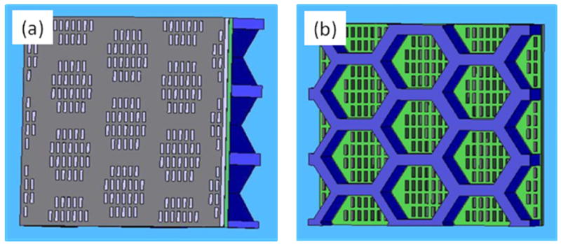
Schematics of magnetic sifter structure. (a) The magnetic layer containing slots (top view). (b) The silicon skeleton and exposed nitride membrane containing slots (bottom view). Film thicknesses are not drawn to scale.
To fabricate the sifter, conventional photolithography and etching techniques are employed. First, a 1 μm thick low-stress silicon nitride (Si3N4) membrane is deposited via low pressure chemical vapor deposition onto a double polished silicon wafer. The Si3N4 membrane is then patterned via photolithography with a mask containing arrays of slots. The pattern is transferred to the membrane through etching in NF3 plasma with an Applied Materials Technologies 8100 Hexode plasma etcher. The backside of the wafer is then patterned with a mask containing arrays of hexagonal holes. The holes are etched completely through the silicon wafer to expose the silicon nitride membrane, by a deep reactive ion etching process in alternating SF6 and C4F8 plasmas (standard Bosch process) using a STS Deep RIE etcher. A 2.6 μm thick Co90Ta5Zr5 (at. %) film is then deposited onto the Si3N4 membrane using a Perkin-Elmer high vacuum rf-sputtering system. A permanent magnet assembly was used to align the easy axis of the magnetic material along the x-axis (Fig. 3) of the sifter during deposition. The magnetic layer is then coated via sputtering with a 30 nm thick layer of SiO2 to render the surface hydrophilic. 120 sifter dies were successfully fabricated with one 100 mm wafer.
Fig. 3.
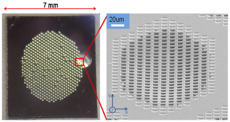
Fabricated magnetic sifter. (Left) Photograph of the sifter die. (Right) SEM of a slot array.
A photograph of a fabricated sifter and a corresponding scanning electron micrograph of a slot array are shown in Fig. 3. Slight curvature is observed in the slot arrays due to film stress following deposition of the magnetic material. For a slot size of 4 × 10 μm, a single sifter die contains 124,032 slots, corresponding to an open area of 5 mm2. The magnetic properties of the sifter were characterized with a B-H loop tracer (Shb Instruments, Inc.). The patterned film exhibited soft magnetic properties, with a Bs value of 1.3 T at an applied field of 6.4 × 10⁴ A/m, a residual induction of ~0.1 T, and a coercivity of 264 A/m. Resistance to corrosion in an aqueous environment was tested by placing the sifter in PBS buffer, pH 7.4, at 37°C for one hour. No degradation of the film’s magnetic properties was observed.
Prior to quantitative magnetic separation experiments, we have conducted qualitative observations of the magnetic sifter with an optical microscope to verify the proposed separation principle. In these experiments, a small drop of MagCellect magnetic nanoparticles (R&D Systems, Inc., Minneapolis, MN), with an average diameter of 150 nm and a concentration of roughly 1011 particles/ml was pipetted onto the sifter surface. An external field of 2.4 × 10⁴ A/m was applied in the plane of the sifter surface along the y-axis (Fig. 3), with a permanent NdFeB magnet. The behavior of the magnetic particles over the sifter surface in response to the application and removal of the applied field was observed and can be summarized as follows. In the absence of an applied field, the particles are dispersed and not visible under the microscope. When the field is applied, within seconds, clusters of magnetic particles appear and are swept into the slots. Upon removal of the field, the particles diffuse from the slots and appear as dark clouds over the sifter surface. After several seconds, the clouds diffuse completely and the particles are no longer visible. The capture and release behavior observed is repeatable for tens of cycles until the drop of magnetic particles dries on the sifter surface.
Observation experiments under a microscope have also been extended to observe the interaction of magnetically-labeled cells with the sifter surface. The results are shown in Fig. 4. For these experiments, cultured human umbilical vascular endothelial cells (HUVEC), at a concentration of roughly 2 × 10⁵/ml, were used. These cells express the platelet/endothelial cell adhesion (PECAM1, CD34) surface marker, for which targeting antibody kits, such as the MagCellect isolation kit, are commercially available. Magnetic labeling is accomplished by adding and incubating biotinylated antibody with the chilled cell suspension for 10 min, followed by the addition of the streptavidin-coated magnetic nanoparticles (ave. diam.=150 nm). The labeled HUVEC were pipetted onto the sifter surface. In the absence of an applied field, the HUVEC were observed scattered about the surface (Fig. 4a), both on the slot arrays and on the unpatterned areas. Applying a field resulted in the majority of cells moving off the pattern-free area and onto the slot arrays (Fig. 4b) where strong local fields originate from magnetic surface charges at the patterned edges. The cells can be released from the slot arrays with removal of the applied field and gentle washing with buffer.
Fig. 4.
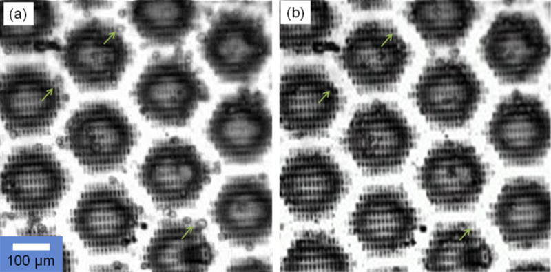
Cell isolation with magnetic sifter. (a) Labeled HUVEC which have settled onto an unmagnetized sifter surface. (b) When an external field is applied, most cells are pulled onto the slotted area where high fields and gradients are generated.
Quantitative magnetic separation experiments have been carried out to assess the potential of the magnetic sifter for applications in biological sample preparation. In these experiments, CD 138 (syndecan-1) antibody-labeled MACS nanoparticles (Miltenyi Biotec, Inc., Auburn, CA) with an average diameter of 50 nm were chosen as a suitable nanoparticle to evaluate the sifter. CD138-MACS particles have been successfully used to concentrate malignant plasma cells from patients diagnosed with multiple myeloma [10]. The particles consist of superparamagnetic iron oxide cores embedded in a dextran matrix. Unlike the MagCellect particles used in the previously mentioned microscope experiments, the MACS particles exhibit negligible interparticle interactions under a microscope.
The separation assembly is shown in Fig. 5. Sifters were sealed with a pair of o-rings by custom-made holders with fluid inlets and outlets. During the capture step, the soft magnetic material of the sifter was magnetized with a uniform field produced by a pair of cylindrical NdFeB magnets (19.1 mm diam. × 12.7 mm thick, BHmax =320–344 kJ/m3). The strength of the external field was measured with a Gaussmeter to be 2.3 × 10⁵ A/m. 200 microliters of fluid containing MACS CD138-labelled magnetic nanoparticles, with a concentration of ~1012 particles/ml, was pumped through the sifter using a syringe pump (New Era Pump Systems, Inc.) at a rate of 1 ml/hr, resulting in a separation time of 12 minutes. The captured particles were released by removing the external field and flushing the sifter with 200 μl of DI water at a rate of 10 ml/hr. To determine capture and elution efficiencies, 10 μl aliquots of the processed fluids were dropcast and dried onto 2 × 2 mm2 pieces of silicon wafer, and the magnetic moment was measured with an alternating gradient magnetometer (Princeton Measurements Corp.).
Fig. 5.
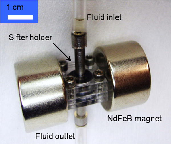
Separation assembly.
Fig. 6 shows the capture and elution results for a typical separation experiment. Before passing through the sifter, a 10 μL aliquot of the magnetic nanoparticle solution was measured to have a peak magnetic moment of 8.18 × 10⁻⁸ Am2 at an applied field of 3.98 × 10⁵ A/m. After passing through the sifter, the magnetic moment was measured to be 5.39 × 10⁻⁸ Am2, indicating a capture efficiency of 34%. After washing with 200 μL of DI water, a 10 μL aliquot of the eluted liquid yielded a magnetic moment of 2.04 × 10⁻⁸ Am2, indicating that 73% of the captured nanoparticles were eluted during the washing step. The same separation experiment was repeated twice with the same sifter. For the second separation, the capture efficiency was measured to be 37%, while the elution efficiency was measured to be 100±10%. The third separation yielded a capture efficiency of 28%, while the elution efficiency was measured to be 86%. Control experiments were conducted in which the magnetic nanoparticle solution was passed through a sifter with no magnetic film, while still applying the external permanent magnets. The capture efficiencies for these experiments were less than 5%.
Fig. 6.
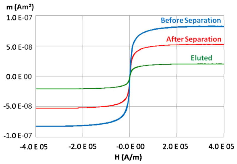
Alternating gradient magnetometry characterization of a separation process.
Scanning electron microscopy (SEM) images were taken of the sifter slots following the separation experiments. Clusters of MACS nanoparticles were observed at the edges of the slots, but were not found elsewhere on the sifter surface.
These preliminary separation results indicate that the microfabricated magnetic sifter is promising for high efficiency and high throughput magnetic separation for analytical applications. The capture efficiencies ranging from 28–37% are expected to improve with optimization of various experimental parameters. One important paramater is the choice of magnetic nanoparticle. Particles which exhibit interparticle interactions such as chaining in a magnetic field will respond more strongly to the field gradients at the slots. Should the chains become sufficiently large, the magnetic sifter may also double as a sieving structure. Optimization of parameters such as magnetic film thickness, slot size, and external field strength are also expected to result in increased capture efficiency. The patterned area of the sifter or even the overall area of a sifter die can also be made larger to allow for increased flow area, which would reduce the velocity of magnetic particles at the slots for a given flow rate. Finally, sifters can easily be placed in series to yield an overall higher capture efficiency.
The elution efficiencies, ranging from 73–100±10%, despite larger variations, are also appreciable. The higher than expected elution efficiency (100±10%) for the second experiment is likely due to the release of nanoparticles previously captured in the first experiment. The ±10% error in elution efficiency is attributed to inhomogeneity in the aliquots, possibly due to the release of large nanoparticle aggregates formed during separation. The variation in elution efficiency for each step, however, is not yet well understood. The observation of MACS nanoparticle clusters at the slot edges following capture and elution indicates that some irreversible binding occurs between the MACS nanoparticles and the sifter surface. This may be reduced or prevented by the use of anti-non-specific binding (blocking) buffers, prior surface modification with antifouling agents such as polyethylene glycol, or a more aggressive elution protocol.
Acknowledgments
We acknowledge the U.S. National Cancer Institute through the Center for Cancer Nanotechnology Excellence, National Science Foundation, and the Stanford Graduate Fellowship program for financial support.
Footnotes
Publisher's Disclaimer: This is a PDF file of an unedited manuscript that has been accepted for publication. As a service to our customers we are providing this early version of the manuscript. The manuscript will undergo copyediting, typesetting, and review of the resulting proof before it is published in its final citable form. Please note that during the production process errors may be discovered which could affect the content, and all legal disclaimers that apply to the journal pertain.
References
- 1.Kuhara M, Takeyama H, Tanaka T, Matsunaga T. Anal Chem. 2004;76:6207. doi: 10.1021/ac0493727. [DOI] [PubMed] [Google Scholar]
- 2.Lara O, Tong X, Zborowski M, et al. Biotechnol Bioeng. 2006;94:66. doi: 10.1002/bit.20807. [DOI] [PubMed] [Google Scholar]
- 3.Bucak S, Jones DA, Laibinis PE, Hatton TA. Biotechnol Prog. 2003;19:477. doi: 10.1021/bp0200853. [DOI] [PubMed] [Google Scholar]
- 4.Gu H, Xu K, Xu C, Xu B. Chem Commun. 2006;9:941. doi: 10.1039/b514130c. [DOI] [PubMed] [Google Scholar]
- 5.Chen H, Kaminski MD, Ebner AD, et al. J Magn Magn Mater. 2007;313:127. [Google Scholar]
- 6.Carpino F, Moore LR, Zborowski M, et al. J Magn Magn Mater. 2005;293:546. [Google Scholar]
- 7.Smistrup K, Lund-Olesen T, Hansen MF, Tang PT. J Appl Phys. 2006;99:08P102. [Google Scholar]
- 8.Inglis DW, Riehn R, Austin RH, Sturm JC. Appl Phys Lett. 2004;85:5093. [Google Scholar]
- 9.Tibbe AGJ, de Grooth BG, Greve J, et al. Cytometry. 2002;47:163. doi: 10.1002/cyto.10060. [DOI] [PubMed] [Google Scholar]
- 10.Draube A, Pfister R, Vockerodt M, et al. Ann Hematol. 2001;80:83. doi: 10.1007/s002770000245. [DOI] [PubMed] [Google Scholar]


