Abstract
A high-resolution Stokes vector imaging polarimeter was developed to measure the polarization properties at the cellular level in living human eyes. The application of this cellular level polarimetric technique to in vivo retinal imaging has allowed us to measure depolarization in the retina and to improve the retinal image contrast of retinal structures based on their polarization properties.
The effect of tissue on the polarization state of light is dependent on both the structural and optical properties of the tissue being measured. Because of this ability to probe biophysical properties of tissues, polarization analysis is being increasingly applied to both imaging and biophysical measurements of tissues [1,2]. In ophthalmic imaging, polarization analysis has been successfully applied to measure nerve fiber layer thickness [3-5], to improve image contrast [6-9], and to emphasize pathological tissue [10,11]. In the past, ophthalmic polarization analysis was restricted to bulk tissue properties; however, with the advent of adaptive optics retinal imaging [12,13] it is now possible to image cellular structures in the living human retina. In the current work we coupled an adaptive optics scanning laser ophthalmoscope (AOSLO) with polarization optics, allowing us to measure the Stokes vector of light returning from retinal cells.
Light returning from the retina of the eye consists of both directly backscattered light and light that has undergone multiple scattering [10,11]. Polarization analysis can help differentiate these sources of light return, since multiply scattered light tends to be depolarized [14]. The retardation in human corneas is nearly constant at the center of the cornea [15] and affects all portions of the retinal image approximately equally. Thus local differences between retinal structures will be preserved, and the degree of polarization will be unchanged. The polarization state of a light beam can be described by a four-element column vector, [S0,S1,S2,S3]T, known as a Stokes vector [16], where S0 represents the total intensity of the light, S1 represents the difference between horizontal and vertical linear components, S2 represents the difference between +45° and -45° linear components, and S3 represents the difference between right and left circular components. The degree of polarization (DOP) [17] is the proportion of light that is polarized, while the degree of depolarization (DODP) is 1-DOP. In this Letter, we report what we believe to be the first measurement of the microscopic polarization properties of the retina by calculating the Stokes vectors of high-resolution AOSLO images. These measurements allow us to quantitatively describe the alterations in the polarization properties of the light by the eye, and to measure the optical properties of specific retinal structures.
We modified an adaptive optics SLO [18] by introducing a half-wave plate into the illumination channel to control the orientation of the linearly polarized beam illuminating the retina. A computer controlled, rotatable zero-order quarter-waveplate (QWP, Thor-labs) followed by a polarizer (Corning PolarCor) were inserted into the detection channel. The QWP was rotated through a series of fixed angles (15° per step, rotate 16 angle positions), and 20 images were recorded for each position of the QWP. All measurements were made using a 500 μm confocal aperture (9× the size of the Airy disc). By using the large aperture, we collect not only the polarized light returning from the retina but also the scattered light, which is more depolarized. This allows us to test the ability to separate information based on polarization state and to increase the total signal. Of the 20 images, approximately 10 images were aligned to subpixel accuracy and averaged using a MATLAB (The Math-works) program developed in house. Cross correlation was used at 35 locations per image, and the centroid of the cross correlations was used to compute the location of best alignment, generating subpixel estimates (centroids were calculated to approximately 1/4 pixel). Images were then aligned using an approach similar to that of Stevenson and Roorda [19]. The averaged images were then aligned to each other, and the intensity of each pixel as a function of the QWP orientation was used to compute the Stokes vector for that pixel by using Eq. (1) [20], solved as a system of 16 equations (one per QWP position) and 4 unknowns:
| (1) |
where S0,S1,S2,S3 are the four elements of the Stokes vector and θ= θ’-θ0, where θ’ is the orientation of the quarter-wave plate and θ0 is the angle between the fast axes of QWP and the polarizer. This difference term was used to ensure alignment of the fast axes of the QWP and the linear polarizer. From the Stokes vector, we computed the intensity of light returning from the retina on a pixel-by-pixel basis for any arbitrary polarization state, as well as the DOP and DODP.
The system polarization properties were calibrated in two steps. First, a polarization analyzer was placed at the exit pupil of the system. This consisted of a rotating QWP, followed by a linear polarizer, followed by a detector. The Stokes vector of the incident light was confirmed to be linearly polarized. Next, a plane mirror was placed at a retinal conjugate plane of an artificial eye; the light returning to the imaging detector, through the imaging system, was measured and the Stokes vector was calculated. The resultant Stokes vector for the double-pass imaging system was [1,0.8064,0.2670,0.4961]T. The DOP was computed to be 0.984, within experimental error of the ideal value of 1.0. To measure the polarization properties of the retina, human subjects were dilated with 0.5% tropicamide. Defocus and astigmatism were corrected by a Badal optometer and ophthalmic trial lenses. A bite bar mounted on a three-axis positioning stage was used to align the subject’s pupil to the exit pupil of the imaging system. The combined intensity of the imaging beam (380 μW, 790 nm) and the wavefront sensing beacon (50 μW, 680 nm) is more than 10× below the ANSI safe exposure level for the field size (400 μm×600 μm). This research was approved by the Indiana University Institutional Review Board and complied with the requirements of the Declaration of Helsinki.
To compare image contrasts, we first selected individual features in an image (such as photoreceptors) and regions adjacent to those features. We then computed the Michelson contrast for each feature, providing an estimate of how the feature varied from neighboring locations. Michelson contrast is calculated as
| (2) |
where Icenter is the intensity of a feature of interest and Iadajecent is the intensity of the adjacent pixels.
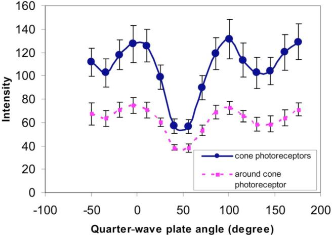
Different structures within an eye differed in their polarization properties. Figure 1 compares the mean intensity of 20 cone photoreceptors and 20 regions selected to be next to cone photoreceptor with respect to the orientation of the quarter wave plate. Data were collected at 6° in the nasal retina. We calculated Stokes vectors based on these samples and found that, as expected, the cones are highly polarization preserving with a DOP between 0.8 and 0.95, while light returning from the edges of cones or between cones has a lower DOP. As a result, the Michelson contrast of cones is higher for the DOP image than for the intensity image (paired-t test, p=0.008).
Fig. 1.

(Color online) Systematic variation of the intensities of cone photoreceptors and area around cone photoreceptors from one subject at 6° of the nasal retina with respect to the orientation of the quarter-wave plate. Error bars are the standard deviation across locations.
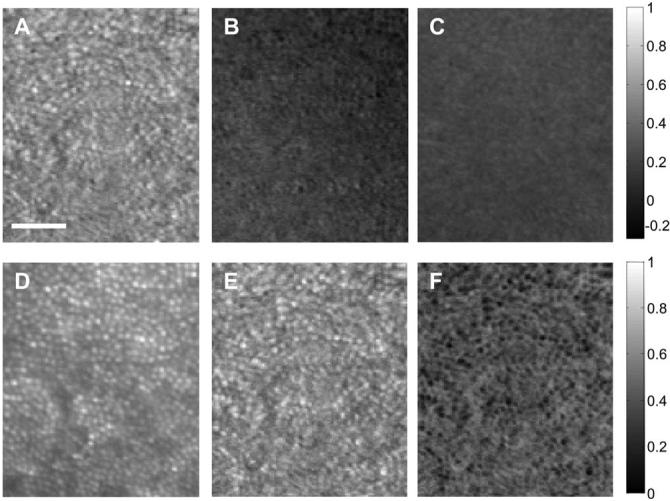
This difference among computed images is shown in image form in Fig. 2. Stokes vector images (S1-S3) are shown in Fig. 2 (top row). From the Stokes vector images we also computed the normalized S0 image (Fig. 2D), the DOP image (Fig. 2E), and the DODP image (Fig. 2F).
Fig. 2.

Stokes vector images at 6° on the nasal retina from the same subject as in Fig. 1. Top row, images formed by S1-S3; bottom row, intensity image (S0), DOP image, and DODP image. Scale bar is 50 μm. The gray-level code is shown at the right side.
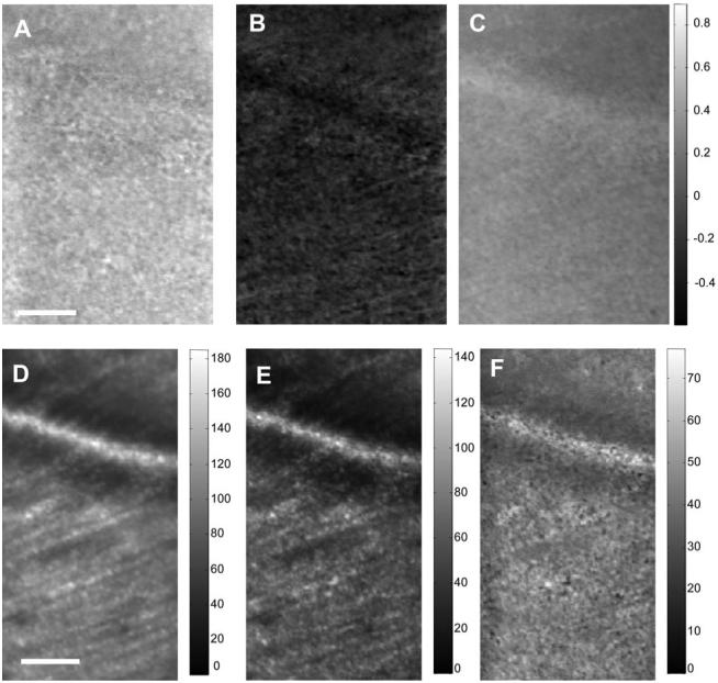
Figure 3 shows results from the same subject when focused on the nerve fiber layer at 7° in the nasal retina. It is clear that different structures affect the polarization state differentially.
Fig. 3.

Top row, Stokes vector images (S1-S3); bottom row, intensity images for all light S0 (left), all polarized light S0 *DOP (middle), and all depolarized light S0 *DODP (right). Scale bar is 50 μm. The gray-level code is shown at the right side on the top row and shown separately on the bottom row. Images are at 7° of the nasal retina from the same subject as Fig. 1.
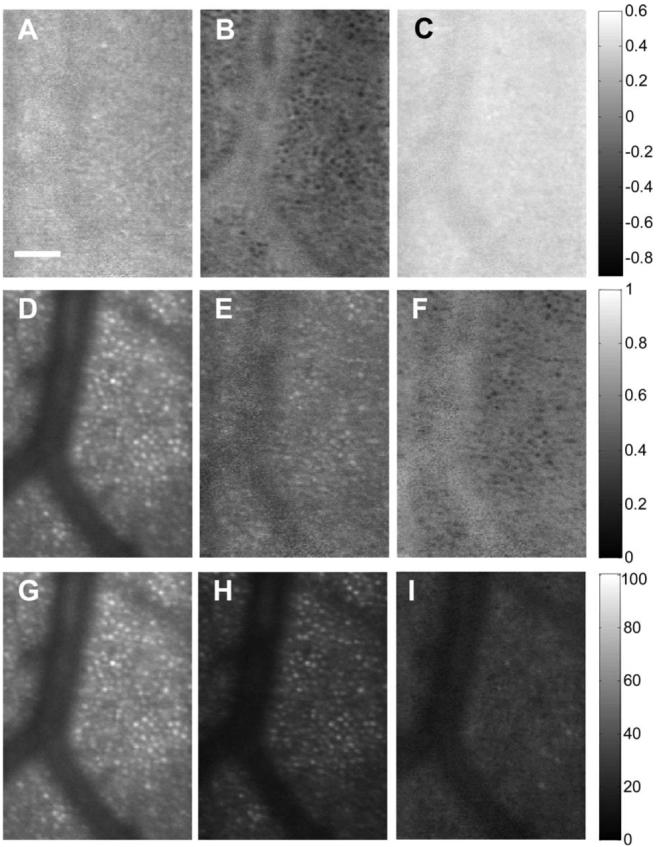
Figure 4 shows results from a second subject in a region with both the shadow of a blood vessel and cone photoreceptors at 6° from the nasal retina. The images corresponding to S1-S3 (Fig. 4, top row) show that in this subject the average polarization state differs from the first subject, presumably due to differences in corneal and nerve fiber birefringence. The images corresponding to the normalized S0, DOP, and DODP (second row) show again that the cones maintain polarization, but light in the shadow region is highly depolarized. The bottom row shows intensity images for all light (S0, Fig. 4G), all polarized light (S0 *DOP, Fig. 4H), and all depolarized light (S0 *DODP, Fig. 4I).
Fig. 4.

Stokes vector images of the retina in a region with both the shadow of a blood vessel and cone photoreceptors at 6° of the second subject’s nasal retina. Scale bar is 50 μm. The gray-level code is shown at the right side.
We have demonstrated that it is possible to use an adaptive optics polarimeter to evaluate the polarization state of light returning from single cells in the human retina. Different parts of the retina return light in different polarization states. For instance, the cones are highly polarization preserving, so using just that portion of the light that maintains polarization greatly increases the contrast of the cone images. Alternatively, the shadows of blood vessels are illuminated by a higher proportion of multiply scattered light and therefore have a higher DODP. These results extend previous studies measuring the preservation of polarization of the human retina [9,21,22]. In conclusion, we have developed a polarimetric technique that can, for the first time to our knowledge, measure the polarization state of light returning from individual cellular structures in the living human eye. The use of polarization analysis has allowed us to distinguish retinal structures and improve the retinal image contrast of specific structures based on polarization properties.
Acknowledgments
This work was supported by NIH grants RO1 EYO7624 and EYO14375.
Footnotes
OCIS codes: 120.3890, 170.4460, 180.1790, 330.4300, 330.4460.
References
- 1.Bueno JM, Campbell MCW. Ophthal. Physiol. Opt. 2003;23:109. doi: 10.1046/j.1475-1313.2003.00095.x. [DOI] [PubMed] [Google Scholar]
- 2.Angelsky OV, Ushenko AG, Ushenko YG. Phys. Med. Biol. 2005;50:4811. doi: 10.1088/0031-9155/50/20/005. [DOI] [PubMed] [Google Scholar]
- 3.Dreher AW, Reiter K. Clin. Vision Sci. 1992;7:481. [Google Scholar]
- 4.Greenfield DS, Knighton RW, Huang XR. Am. J. Ophthalmol. 2000;129:715. doi: 10.1016/s0002-9394(00)00353-6. [DOI] [PubMed] [Google Scholar]
- 5.Cense B, Chen HC, Park BH, Pierce MC, de Boer JF. J. Biomed. Opt. 2004;9:121. doi: 10.1117/1.1627774. [DOI] [PubMed] [Google Scholar]
- 6.Miura M, Elsner AE, Cheney MC, Usui M, Iwasaki T. J. Opt. Soc. Am. A. 2007;24:1431. doi: 10.1364/josaa.24.001431. [DOI] [PMC free article] [PubMed] [Google Scholar]
- 7.Bueno JM, Hunter JJ, Cookson CJ, Kisilak ML, Campbell MCW. J. Opt. Soc. Am. A. 2007;24:1337. doi: 10.1364/josaa.24.001337. [DOI] [PubMed] [Google Scholar]
- 8.Mellem-Kairala MB, Elsner AE, Weber A, Simmons RB, Burns SA. Invest. Ophthalmol. Visual Sci. 2005;46:1099. doi: 10.1167/iovs.04-0574. [DOI] [PubMed] [Google Scholar]
- 9.Bueno JM, Campbell MCW. Opt. Lett. 2002;27:830. doi: 10.1364/ol.27.000830. [DOI] [PubMed] [Google Scholar]
- 10.Burns SA, Elsner AE, Mellem-Kairala MB, Simmons RB. Invest. Ophthalmol. Visual Sci. 2003;44:4061. doi: 10.1167/iovs.03-0124. [DOI] [PMC free article] [PubMed] [Google Scholar]
- 11.Weber A, Cheney MC, Smithwick QYJ, Elsner AE. Opt. Express. 2004;12:5178. doi: 10.1364/opex.12.005178. [DOI] [PubMed] [Google Scholar]
- 12.Roorda A, Romero-Borja F, Donnelly WJ, Queener H, Hebert TJ, Campbell MCW. Opt. Express. 2002;10:405. doi: 10.1364/oe.10.000405. [DOI] [PubMed] [Google Scholar]
- 13.Liang J, Williams DR, Miller DT. J. Opt. Soc. Am. A. 1997;14:2884. doi: 10.1364/josaa.14.002884. [DOI] [PubMed] [Google Scholar]
- 14.Jarry G, Steimer E, Damaschini V, Epifanie M, Jurczak M, Kaiser R. Appl. Opt. 1998;37:7357. doi: 10.1364/ao.37.007357. [DOI] [PubMed] [Google Scholar]
- 15.Bueno JM, Vargas-Martin F. Appl. Opt. 2002;41:116. doi: 10.1364/ao.41.000116. [DOI] [PubMed] [Google Scholar]
- 16.Shurcliff WA. Polarized Light: Production and Use. Harvard U. Press; 1962. [Google Scholar]
- 17.Chipman RA. Handbook of Optics. Vol. 2. McGraw-Hill; 1995. pp. 22.21–22.37. [Google Scholar]
- 18.Burns SA, Tumbar R, Elsner AE, Ferguson D, Hammer DX. J. Opt. Soc. Am. A. 2007;24:1313. doi: 10.1364/josaa.24.001313. [DOI] [PMC free article] [PubMed] [Google Scholar]
- 19.Stevenson SB, Roorda A. Proc. SPIE. 2005;5688A:145. [Google Scholar]
- 20.Williams PA. Appl. Opt. 1999;38:6508. doi: 10.1364/ao.38.006508. [DOI] [PubMed] [Google Scholar]
- 21.Blokland GJV, Norren DV. Vision Res. 1986;26:485. [Google Scholar]
- 22.Bueno JM, Artal P. Opt. Lett. 1999;24:64. doi: 10.1364/ol.24.000064. [DOI] [PubMed] [Google Scholar]


