Abstract
In this manuscript, we report on the culture of anaerobic and aerobic species within a disposable multilayer polydimethylsiloxane (PDMS) microfluidic device with an integrated differential oxygenator. A gas-filled microchannel network functioning as an oxygen−nitrogen mixer generates differential oxygen concentration. By controlling the relative flow rate of the oxygen and nitrogen input gases, the dissolved oxygen (DO) concentration in proximal microchannels filled with culture media are precisely regulated by molecular diffusion. Sensors consisting of an oxygen-sensitive dye embedded in the fluid channels permit dynamic fluorescence-based monitoring of the DO concentration using low-cost light-emitting diodes. To demonstrate the general utility of the platform for both aerobic and anaerobic culture, three bacteria with differential oxygen requirements (E. coli, A. viscosus, and F. nucleatum), as well as a model mammalian cell line (murine embryonic fibroblast cells (3T3)), were cultured. Growth characteristics of the selected species were analyzed as a function of eight discrete DO concentrations, ranging from 0 ppm (anaerobic) to 42 ppm (fully saturated).
Monitoring and controlling the dissolved oxygen (DO) concentration in medium are critical for biological culture and tissue engineering applications. Cellular growth, especially biofilm formation, involves the complex correlations of growth environment1,2 and cell−cell communications among cellular species.3,4 For cellular growth analysis, including the single cells/small cell clusters(5) monitoring, precise control of the cellular environment is clearly desirable. Several microscale silicone-based chemostats,6−8 bioreactors,9−12 and other microfluidic platforms13,14 containing multiple cell chambers have been developed for this purpose. Such platforms were engineered to provide moderate to long-term control (on the order of hours to days) of the microenvironment, including elements such as temperature, pH value, dissolved gas concentration, nutrient delivery, and waste removal. Due to the reproducibility and biocompatibility of soft lithography,(15) the structural material choice of many microfluidic platforms is polydimethylsiloxane (PDMS), which has an oxygen diffusivity (DO2-PDMS ∼6 × 10⁻⁵ cm2/s)(16) on the same order as water at standard temperature and pressure (STP) (20 °C, 101.325 kPa).(17)
Controlling local DO levels in PDMS microfluidic devices can be achieved by flowing oxygen through dedicated gas microchannels that are in close proximity to the fluid-filled microchannels. Using conventional soft lithography methods,15,18 a small separation between gas and fluid microchannels on the order of tens of micrometers can readily be achieved. Several methods to regulate medium oxygenation using integrated microfluidic gas channels have been recently reported.8,19−22 A double-layer gas perfusion network structure fabricated above the cell culture region was designed for parallel mammalian cell culture.(23) Using a continuous oxygen supply, identical DO levels were maintained within an array of wells via passive gas diffusion. Recently, Polinkovsy and colleagues developed a multilayer PDMS-based microfluidic device consisting of an oxygen−nitrogen mixer to generate local differential DO microenvironments for cell culture applications.(24) In their work, the preliminary culture analysis using fluorescence microscopy illustrated E. coli growth as a function of DO concentration, and highlighted the potential to use controlled oxygenation microfluidic devices for both prokaryotic and eukaryotic cell culture applications where low DO levels or anaerobic environments are desirable.
For low pO2 (partial pressure of oxygen) microculture systems, dynamic monitoring of the DO levels is critical for long-term culture viability. While Clark-type electrodes have been used for almost half a century to measure DO levels in aqueous media,25,26 these devices irreversibly convert oxygen molecules to hydroxide ions that are potentially harmful to cells. Moreover, miniaturizing and integrating such electrodes into microscale flow devices is challenging, limited by fabrication complexity, noise, and run-to-run signal drift. Noncontact optical sensors represent a better alternative for the DO measurement in biofluidic systems.27−29 They typically consist of an oxygen-permeable polymer film embedded with a sensing material, e.g. Pt/Pd-porphyrin complexes,(30) polyaromatic hydrocarbon complexes,(31) or ruthenium dimines.(32) The operation principle is based on the reduction in luminescent intensity of sensing material, due to the oxygen quenching of the emitting excited electronic state. Recently, a method to fabricate Pt-porphyrin complexes as patterned polymeric films with consistent film thickness and a high signal-to-noise ratio has been presented.(33) Porphyrin-based sensors are a practical choice for real-time microfluidic oxygen sensing, providing the benefits of reversible quenching, high sensitivity, and biocompatibility.34,35
In this manuscript, we present a PDMS microfluidic oxygenation system that provides a step-function gradient of DO concentrations across parallel microchannels for the monitoring of culture growth dynamics versus medium oxygen levels.(36) The ability to vary and tune pO2 in a microfluidic environment has practical applications in areas such as microbiology and cancer research,(37) where fluctuations in DO concentration impact not only cell viability but also the regulation of key biochemical pathways. The multilayer microfluidic device consists of a gas-based analog of a microfluidic solution gradient generator(38) similar to the design utilized by Polinkovsky et al.,(24) with a network of branching gas-filled microchannels that overlap the underlying microfluidic culture channels. Similar to the chemical solution gradient generator, which has been applied in chemotaxis studies(39) and continuous cell culture,(40) gases like oxygen and nitrogen are mixed like liquids, with a parallel output of streams containing a stepwise gradient of oxygen concentrations. By varying the dimensions of the individual microchannels within the mixer network, the output oxygen concentration(s) can be finely tuned for the target application. Oxygenation of culture media is achieved by the double-layer gas perfusion channel structure along the cell culture region. While the Polinkovsky platform used an inverted fluorescent microscope to monitor oxygenation with a solution-based fluorescent dye, the monitoring in our platform is achieved with an array of optical (Pt-porphyrin) oxygen sensors embedded in each culture channel that provides a real-time medium DO measurement with low-cost light-emitting diodes. To validate such platform, the growth characteristics of murine embryonic fibroblast cells (3T3) and bacteria with different DO requirements, including Escherichia coli (facultative anaerobe), Actinomyces viscosus (aerobe) and Fusobacterium nucleatum (anaerobe), have been analyzed as a function of eight discrete DO concentrations, ranging from anaerobic to fully saturated.
Experimental Section
Oxygen-Sensing System
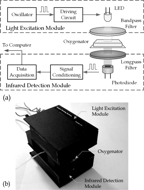
Real-time oxygen concentration measurement is achieved by an optical oxygen-sensing system. Platinum(II) octaethylporphine ketone (PtOEPK) was selected as the optical sensing element, because of its long lifetime, high photostability, and low photobleaching rate among other fluorescent dyes. The excitation (570 nm) and emission (760 nm) wavelengths of PtOEPK induce a large Stokes shift to reduce the signal-to-background ratio.41,42 A schematic diagram of the oxygen-sensing scheme is illustrated in Figure 1a. The excitation light is generated by a yellow light-emitting diode (LED) with a bandpass color filter (CVI laser, BG-39) placed between the LED and the microfluidic oxygenator chip. The PtOEPK dye, which is embedded in polystyrene films that are integrated into the fluid channels of the oxygenator, re-emits light with an intensity corresponding to the oxygen concentration. The emitted light is detected by a photodiode (OPT101) with a long-pass color filter (CVI laser, LP-720). After further signal processing, the signal is fed to computer via a data acquisition unit.
Figure 1.
(a) Mechanism of optical oxygen concentration measurement. The measurement is achieved by passing yellow light through the microfluidic oxygenator from a LED source. The infrared detection module receives re-emitted light from an oxygen sensor, performs basic signal processing, and sends signals to a computer. (b) Oxygen detection system. During DO measurement, the microfluidic device is placed between the light excitation module and the infrared detection module.
To minimize the oxygen measurement sensitivity to ambient light, we applied an oscillating voltage to drive the LED instead of a direct current (DC) voltage. The photodiode receives an oscillating intensity with a frequency matched to the driving signal. By choosing a high oscillating frequency (on the order of kilohertz), the ambient intensity can be filtered out by a high-pass signal filter (with a cutoff frequency of 1.6 kHz). Afterward, the amplitude of the extracted oscillating signal is converted to a steady voltage by the signal conditioning circuit, which contains a rectifier, low-pass filters, and amplifiers. (The circuit diagrams for the light excitation module and the infrared detection module are available as Supporting Information.) The modified signal is fed into the serial port of a computer, where the mean signal output voltage is correlated with the oxygen concentration using a data acquisition module (DI-194RS, DataQ Instruments). The packaged oxygen sensing system is shown in Figure 1b. The overall sampling rate of the oxygen-sensing system is 240 Hz, which is sufficient given the equilibration time of DO in the embedded sensors (∼1−3 min, depending on the media flow rate). Post-analysis of the measured data was performed using a script written in Visual C++.
Microfluidic Oxygenator Device Fabrication
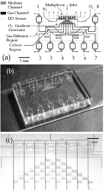
The PDMS microfluidic oxygenator consists of an array of eight microchannels (20 μm (height) × 100 μm (width)) that provides differential DO concentrations (channel-to-channel) for cell culture. The chip has a double-layer channel structure, with the design layout illustrated in Figure 2a. The fabrication process was based on previously reported multilayer soft lithography methods.(18) The mold with medium channel patterns was prepared by patterning two layers of 10-μm-thick positive AZ4620 photoresist (AZ Electronic Materials) on a 3-in. silicon wafer (James River Semiconductors), followed by a 1-min. reflow at 150 °C. Photolithography (12 s × 3 exposure) was performed using a high-resolution transparency mask (∼20 000 dpi). SU-8 negative photoresist was selected for the gas channel mold. A 40-μm-thick SU-8 (Microchem SU-8 50) layer was spin-coated on a 3-in. wafer and patterned by photolithography (Karl Suss Mask Aligner MJB3, 75 s exposure). Afterward, the molds were silanized with a high-molecular-weight trichloro-perfluorooctyl saline (Aldrich) for ∼5 min to facilitate PDMS mold release.(43) The silanization process reduces the adhesion of PDMS to Si/SU-8 and Si/AZ4620 surfaces, to increase the mold lifetime.
Figure 2.
(a) Schematic diagram of microfluidic oxygenator. The device consists of two PDMS layers (gas and medium) that contain molded microchannels. The multiplexor and O2 gradient generator are contained in the gas layer, while the DO sensors are contained in the medium channels. (b) Fabricated microfluidic oxygenator. (c) Micrograph of the multiplexor and the oxygen concentration gradient generator.
The oxygen sensor array was prepared by wet-etching the sensor pad regions on a glass substrate, followed by deposition of a PtOEPK film. To initiate the process, a sacrificial layer of AZ4620 photoresist (10 μm) was spin-coated on the surface and patterned by photolithography. The exposed sensor regions were then etched with buffered hydrofluoric acid (7:1 ratio of H2O to HF) for 15 min. After etching, the protective photoresist layer was stripped with acetone, and a droplet (∼1 μL) of PtOEPK dye solution was applied using a pipet tip to each sensor region. The stock PtOEPK dye solution in the polymer matrix was prepared by mixing PtOEPK (1 mg) with polystyrene (50 mg) and toluene (950 μL). After applying the dye droplets, the solvent rapidly evaporated, leaving behind a thin film (2−4 μm) of dye-embedded polymer.
The molding and assembly of the gas and fluid channels networks was achieved via multilayer soft lithography.(18) A 10:1 A:B two-part PDMS compound (Sylgard 184, Dow Corning) was mixed and poured onto the SU-8/silicon mold that contained a multiplexor(44) and gas channels to a thickness of ∼6 mm. The mold was subsequently degassed in a vacuum bell jar for ∼10 min before it was baked in an oven for 1 h at 80 °C. For the fluid channel mold, 10:1 PDMS was spin-coated (2300 rpm, 50 s) to a thickness of ∼40 μm and baked for 10 min at 80 °C. After the initial bake, both molds were removed from oven for alignment. The ∼6-mm-thick PDMS gas mold replicate was released from the mold and cut to size with a razor blade. A blunt-tipped 20G surgical steel Luer stub was used to punch gas inlet and outlet holes in the PDMS. After punching, an isopropyl alcohol wash was applied to remove debris, followed by drying under a nitrogen stream. The processed thick PDMS gas layer was then aligned over the spin-coated fluid layer under a dissecting scope (Olympus, Model SZX9). To bond the two layers, the composite PDMS substrate was post-baked in an oven for >2 h at 80 °C. The devices were then cut from the flow mold and the fluid layer inlet/outlet holes were punched as previously described. The assembled PDMS was subsequently bonded to the prepared glass substrate that contained the sensor film, using oxygen plasma (Plasmod, Tegal Corporation, 600 mTorr) for 15 s, with the composite device shown in Figures 2b and 2c.
Sensor Calibration
Experiments were initially conducted to calibrate the sensor parameters for the array of PtOEPK−polystyrene films in the microfluidic oxygenator chip. The calibration was conducted by applying oxygenated/partially oxygenated water along a fluidic channel with a flow rate of 0.01 μL/min. Water samples with different DO levels were obtained by mixing different volumetric ratios (4:0, 3:1, 2:2, 1:3, and 0:4) of oxygenated and deoxygenated water, which were respectively prepared by bubbling oxygen and nitrogen into distilled water for 15 min. Using the stabilized intensity readings (defined in terms of the output voltage from the infrared detection module) for the array of sensors, DO concentration was correlated with the emission intensity of the PtOEPK dye through the Stern−Volmer relation:(34)
where I is the emitting fluorescence intensity, I0 the intensity in a deoxygenated state, and KSV is the Stern−Volmer constant.
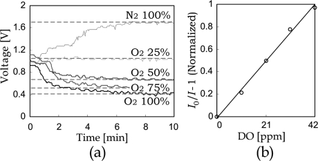
The Stern−Volmer constant and the deoxygenated state intensity of PtOEPK are unique for each sensor, because of the thickness variation of evaporated PtOEPK−polystyrene films. Consequently, in the fabricated test module, every DO sensor in the oxygenator was individually calibrated to determine their corresponding sensor parameters (I0 and KSV) for the least-squares error corresponding to the DO levels in water samples. The calibration result of a representative sample sensor is presented in Figure 3. Figure 3a shows the emitting signal intensity (I), in terms of output voltage as a function of time, for a panel of oxygen/nitrogen ratios ranging from nitrogenated to fully oxygenated. Typical equilibration time for the sensor is on the order of 3 min, based on the diffusivity of oxygen in the polystyrene sensor matrix. Figure 3b shows that the DO level in water has a good agreement with the Stern−Volmer relation.
Figure 3.
Calibration result of oxygen sensor under aqueous environments. After changing the oxygenation condition of liquid inside the channel, the sensor intensity is allowed to stabilize over a period of 3 min. (a) Output signal (voltage) versus time as a function of oxygen concentration in the liquid-filled microchannels for different oxygen concentrations using a typical PtOEPK sensor. (b) Dimensionless output sensor intensity versus DO levels, as defined by the Stern−Volmer relation.
Cell Seeding
3T3 Murine Embryonic Fibroblast
The microfluidic oxygenator was sterilized by flushing fluid channels with 70% ethanol, followed by baking at 80 °C for 2 h. After baking, the fluid channels were rinsed with 1× phosphate-buffered saline (PBS), with pH 7.4, and degassed by forcing trapped air through the walls of the gas-permeable oxygenator with pressurized PBS buffer. The glass surface along flow channels was subsequently precoated with 20 mg/mL gelatin (Sigma) in 1× PBS for 1 h to promote cell attachment. Excess gelatin was removed by rinsing with 1× PBS. In preparation for device loading, the cell line was trypsinized, spun down in a centrifuge (1000 rpm, 5 min), and reconstituted in Leibovitz’s L-15 medium (Invitrogen 11415064) at a density of ∼106 cells/mL. To load cells into the oxygenator, a syringe pump (PicoPlus, Harvard Apparatus) was used to inject cells into each culture channel (flow rate = 0.01 μL/min, load time = 3 min), activated by an integrated microfluidic multiplexor.(44) (Detailed protocols for culturing all cell lines, mammalian and bacteria, are available as Supporting Information.)
E. coli, A. viscosus, and F. nucleatum
The microfluidic devices were sterilized, rinsed, and degassed, following the aforementioned protocol for mammalian cells. Confluent bacteria cultures of each species (OD600 0.95) were diluted in their respective media to a cell density of ∼107 cells/mL. Following dilution, cells were loaded into the oxygenator at a flow rate of 0.01 μL/min for 3 min. Prior to on-chip oxygenated culture, the microfluidic devices for E. coli and A. viscosus were placed in a 37 °C aerobic incubator for 2 h to promote adhesion between the bacteria and glass microchannel wall, while the devices for F. nucleatum were anaerobically cultured by flowing pure nitrogen through the gas-layer microchannel network.
Results and Discussion
Design of Oxygen Gradient Generator
The gas layer in microfluidic oxygenator is composed of microchannels with a constant height (40 μm) and variable width (ranging from 20 μm to 2 mm), and a summary of the calculated equivalent resistances is listed in Table 1. Different oxygen levels are generated by continuously flowing gases with constant input pressure. With corresponding scaled Reynolds numbers (Re*) in the range of ∼10−3−10−1, viscous effect dominates over the inertial one; and the fluidic resistance R of an individual microchannel can be estimated as a rectangular channel, given by
where μ is the fluid viscosity, L the channel length, W the channel width, and H the channel height. The value of μ is dependent on the ratio of oxygen and nitrogen along an individual channel, and it is approximated as
where CO2 and CN2 are the volumetric concentrations of oxygen and nitrogen, respectively; μO2 and μN2 are the respective viscosities of oxygen and nitrogen.
Table 1. Dimensions of Channels in Gas Layer, and the Corresponding Fluidic Resistances, Scaled Reynolds Numbers (Re*), and Scaled Peclet Numbers (Pe*).
| Dimensions |
||||||
|---|---|---|---|---|---|---|
| channel | W [μm] | H [μm] | L [μm] | maximum resistance [Ns/m5] | maximum Re*a | maximum Pe*b |
| Rin | 100 | 40 | 7000 | 3.51 × 10¹¹ | 0.023 | 0.14 |
| Rout | 100 | 40 | 18000 | 9.02 × 10¹¹ | 0.003 | 0.03 |
| Rv | ∼20 | 40 | ∼2000 | 2.19 × 10¹² | 0.009 | 0.08 |
| Rh | 100 | 40 | 500 | 2.51 × 10¹⁰ | 0.267 | 0.11 |
Re* ≈ ρUL/μ × H2/L2.
Pe* ≈ UW/D × W/L.
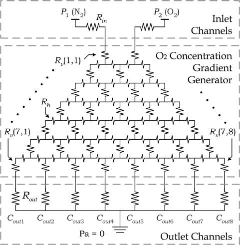
Modeling each individual channel as the fluidic equivalent of an electrical resistor, the gas-layer network is simplified to an equivalent circuit, as illustrated in Figure 4. In the circuit model, the electrical voltage represents the gas pressure while the current represents the gas flow rate. The gas supplies were regulated to the same gauge pressure. By adjusting the effective fluidic resistance of each individual channel, a gradient generator requiring low input gas pressures (i.e., P1 = P2 = 1 kPa) can be achieved. The resistances of folded channels (Rv) are set to be much larger than the common resistance of interconnecting channels (Rh), such that a linear distribution of oxygen concentrations at the respective series of microchannel outlets can be obtained by adjusting only the Rv values.
Figure 4.
Circuit model of the oxygen gradient generator.
Using the assumption that nitrogen and oxygen are fully mixed in every folded microchannel, the volumetric ratios of oxygen along the outlet channels can be estimated. The validity of such assumption is supported by the low scaled Peclet number in the gas microchannels (i.e., Pe* ≪ 1), with diffusion dominating over convective fluxes. For a folded channel that has two inlets with different flow rates and oxygen concentrations, the corresponding oxygen concentration C after mixing can be estimated based on the conservation of mass:
where Q1 and Q2 are the flow rates of the channel inlets, which are resolved by the circuit model; and C1 and C2 are the corresponding oxygen concentrations.
The oxygen ratios along outlet channels (Cout1−Cout8 in Figure 4) were calculated as 0%, 14.2%, 28.49%, 42.82%, 57.18%, 71.53%, 85.81%, and 100%, respectively. This result has also been validated by computational software, as described in the Supporting Information. This implies a homogeneous discrete oxygen gradient can be achieved by mixing N2 and O2 with the proposed gradient generator, which is equivalent to the approach described in ref (24).
Generation of DO Concentrations
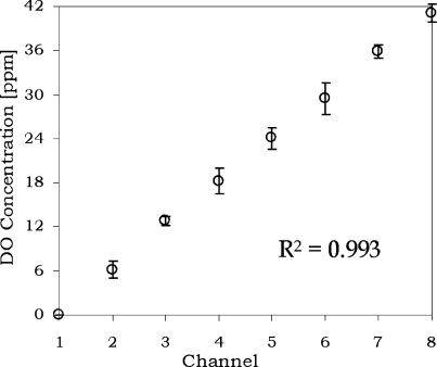
The distribution of DO concentrations along cell culture channels under continuous flow was investigated experimentally. In each measurement, the multiplexor valve array was used to open a single medium channel with steady flow rate controlled by a syringe pump (PicoPlus, Harvard Apparatus). The culture channels are located at the middle sections in the diffusion region, as shown in Figure 2a. The scaled Peclet number along the culture channels is <0.03 (see Table 1). Consequently, the medium DO level will be fully diffused within ∼100 μm,(45) and, therefore, the cell culture and sensor regions will have steady oxygenation conditions. With sensors located outside the culture region, the DO sensing mechanism can obtain the simultaneous pO2 monitoring and cell density analysis. The experimental results (Figure 5) show that the oxygenator can generate different DO levels along channels, which correlate with the oxygen concentrations from the gradient generator mentioned in the previous section. In addition, repeatable results were obtained with a low variation (R2 > 0.99) between separate runs.
Figure 5.
Experimental values of DO concentrations in diffusion channels. The regression (R2) was calculated by the average of four individual experimental data.
Mammalian Cell Culture
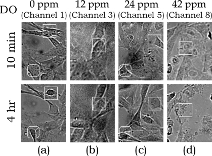
To study the effect of DO concentration on mammalian cell culture, the oxygenator chip was used for parallel culture of BALB murine embryonic fibroblast cells (3T3). Cells were first seeded into culture channels and precultured in an incubator (∼21% O2 and 5% CO2 gas supply) for one day to allow cell spreading and attachment to the treated glass surface. During on-chip cell culture, oxygen and nitrogen (supply pressure ≈ 1 kPa), humidified by bubbling through water reservoirs, were flowed through the gradient generator to generate different DO levels in the underlying medium-filled channels (0−42 ppm). A syringe pump (Harvard Apparatus) was used to supply fresh medium continually (flow rate = 0.003 μL/min) to each fluid channel in turn, switching channels every minute under the control of an integrated microfluidic multiplexor. This operation provides a consistent medium supply along every channel, even when there were inconsistencies in the channel cross sections and fluidic resistances developed by different cell growth rates. After 4 h, the effect of DO on 3T3 cell growth in the culture region could be observed (see Figure 6). The cells exhibited good viability and proliferation at a DO concentration of 12 ppm (Figure 6b). Under low pO2 (<6 ppm), 3T3 cells shrank and started detaching from the channel wall (Figure 6a), while in high pO2 (>36 ppm), cell necrosis was observed (Figure 6d). A comparative traditional culture experiment of 3T3 cells in flasks incubated at 37 °C under pure nitrogen, 21% O2 and 100% O2 yielded morphological results consistent with that of the microfluidic oxygenator, in which 3T3 cells grown under nitrogen detached, while pure O2 resulted in necrosis. (Micrographs of traditional cell culture under variable oxygenation levels are provided as Supporting Information).
Figure 6.
Growth of 3T3 cells under different DO concentrations: (a) 0 ppm, (b) 12 ppm, (c) 24 ppm, and (d) 42 ppm. White boxes indicate changes of cells in specific channel regions during the culture experiment.
Bacteria Cell Culture
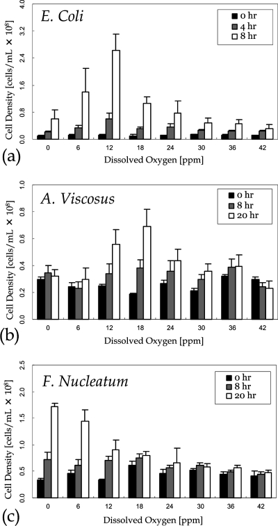
Culture Experiments were also performed with the facultative anaerobe E. coli, the aerobe A. viscosus, and the obligate anaerobe F. nucleatum. Fresh medium was supplied with the same protocol as the mammalian cell culture. To estimate the cell density of bacteria over different culture durations, phase-contrast microscopy images of the culture channel were obtained and compared to control images in which the cell densities (106−108/mL) were measured by a hemocytometer. In the culture region, bacterial communities, which were darker in microscopic images, were extracted by thresholding on image intensity. Results (Figure 7) show that E. coli (Figure 7a) cells grew under both aerobic and anaerobic conditions, with the shortest doubling time (Td = 1.9 h) under ambient condition (pO2 ≈ 12 ppm). A. viscosus (Figure 7b) grew only under aerobic conditions, with the shortest doubling time (Td = 14.1 h) at pO2 ≈ 18 ppm. F. nucleatum (Figure 7c) exhibited maximum growth under anaerobic conditions (Td = 9.67 h), with some growth observed up to pO2 ≈ 12 ppm.
Figure 7.
Cell density of (a) E. coli, (b) A. viscosus, and (c) F. nucleatum. The data points were obtained by averaging the results of five individual experiments. The minor reduction of cell densities observed in A. viscosus (42 ppm) and F. nucleatum (30 ppm) was due to cell detachment.
Conclusion
In this manuscript, the application of a microfluidic differential oxygenator system to the culture of mammalian cells and bacteria with different oxygen demands has been described. Integrating the multiplexor, oxygen−nitrogen gas mixer, and double-layer diffusion channels, the oxygenator generates a step function of repeatable DO concentrations in an array of parallel microchannels containing aqueous media. Integrated polymeric oxygen sensors provide a robust method for real-time monitoring of the DO levels in culture media within the microchannels. To validate its potential for the culture of both eukaryotic and prokaryotic cells, on-chip growth profiles of a model mammalian cell line (3T3), as well as anaerobic and aerobic bacteria, were demonstrated. The culture experiments showed differential cellular growth response verses DO concentrations. Microfluidic oxygenator chips, representing a robust and low-cost method to regulate DO levels in culture, are anticipated to be of wide appeal not only to cancer researchers, but also to public health laboratories for bacteria that are difficult to culture using established microbiology protocols.
Acknowledgments
This work is funded by National Institute of Dental and Craniofacial Research (NIDCR) (under Grant No. 1-R21-DE617412-01). The authors would like to acknowledge the financial support from the Croucher Foundation. The authors also thank Marcos for a fruitful discussion.
Supporting Information Available
Information regarding the circuit design of oxygen sensing system, the cell culture, the cell extraction of Actinomyces viscosus, the simulation of oxygen gradient generation, and bulk culture of murine embryonic fibroblast cells under different oxygen conditions, including referenced literature. This material is available free of charge via the Internet at http://pubs.acs.org.
Supplementary Material
References
- Rickard A. H.; Gilbert P.; High N. J.; Kolenbrander P. E.; Handley P. S. Trends Microbiol. 2003, 11, 94–100. [DOI] [PubMed] [Google Scholar]
- Marsh P. D. Caries Res. 2004, 38, 204–211. [DOI] [PubMed] [Google Scholar]
- Visnovsky G. A.; Smalley D. J.; O’Callaghan M.; Jackson T. A. Biocontrol Sci. Technol. 2008, 18, 87–100. [Google Scholar]
- Manuilova E. I.; Kambourova M. S. World J. Microbiol. Biotechnol. 1991, 8, 21–23. [DOI] [PubMed] [Google Scholar]
- Carlo D. D.; Wu L. Y.; Lee L. P. Lap Chip 2006, 6, 1445–1449. [DOI] [PubMed] [Google Scholar]
- Balagadde F. K.; You L.; Hansen C. L.; Arnold F. H.; Quake S. R. Science 2005, 309, 137–140. [DOI] [PubMed] [Google Scholar]
- Groisman A.; Lobo C.; Cho H.; Campbell J. K.; Dufour Y. S.; Stevens A. M.; Levchenko A. Nat. Methods 2005, 2, 685–689. [DOI] [PubMed] [Google Scholar]
- Zhang Z.; Boccazzi P.; Choi H.-G.; Perozziello G.; Sinskey A. J.; Jensen K. F. Lab Chip 2006, 6, 906–913. [DOI] [PubMed] [Google Scholar]
- Lee P. J.; Hung P. J.; Rao V. M.; Lee L. P. Biotechnol. Bioeng. 2006, 94, 5–14. [DOI] [PubMed] [Google Scholar]
- Lee H. L. T.; Boccazzi P.; Ram R. J.; Sinskey A. J. Lab Chip 2006, 6, 1229–1235. [DOI] [PubMed] [Google Scholar]
- Szita N.; Boccazzi P.; Zhang Z.; Boyle P.; Sinskey A. J.; Jensen K. F. Lab Chip 2005, 5, 819–826. [DOI] [PubMed] [Google Scholar]
- Zenzotto A.; Szita N.; Boccazzi P.; Lessard P.; Sinskey A. J.; Jensen K. F. Biotechnol. Bioeng. 2004, 87, 243–254. [DOI] [PubMed] [Google Scholar]
- Tourovskaia A.; Masot X. F.; Folch A. Lab Chip 2005, 5, 14–19. [DOI] [PubMed] [Google Scholar]
- Brischwein M.; Motrescu E. R.; Cabala E.; Otto A. M.; Grothe H.; Wolf B. Lap Chip 2003, 5, 234–240. [DOI] [PubMed] [Google Scholar]
- Xia Y.; Whitesides G. M. Annu. Rev. Mater. Sci. 1998, 28, 153–184. [Google Scholar]
- Brandrup J.; Immergut E. H.. Polymer Handbook, 2nd ed.; Wiley: New York, 1974. [Google Scholar]
- Shiku H.; Saito T.; Wu C.-C.; Yasukawa T.; Yokoo M.; Abe H.; Matsue T.; Yamada H. Chem. Lett. 2006, 35, 234–235. [Google Scholar]
- Unger M. A.; Chou H.-P.; Thorsen T.; Scherer A.; Quake S. R. Science 2000, 288, 113–116. [DOI] [PubMed] [Google Scholar]
- Leclerc E.; Sakai Y.; Fujii T. Biotechnol. Prog. 2004, 20, 750–755. [DOI] [PubMed] [Google Scholar]
- Higgins J. M.; Eddington D. T.; Bhatia S. N.; Mahadevan L. Proc. Natl. Acad. Sci. U.S.A. 2007, 104, 20496–20500. [DOI] [PMC free article] [PubMed] [Google Scholar]
- Beebe D. J.; Mensing G. A.; Walker G. M. Annu. Rev. Biomed. Eng. 2002, 4, 261–286. [DOI] [PubMed] [Google Scholar]
- Hung P. J.; Lee P. J.; Sabounchi P.; Lin R.; Lee L. P. Biotechnol. Bioeng. 2005, 89, 1–8. [DOI] [PubMed] [Google Scholar]
- Kane B. J.; Zinner M. J.; Yarmush M. L.; Toner M. Anal. Chem. 2006, 78, 4291–4298. [DOI] [PubMed] [Google Scholar]
- Polinkovsky M.; Gutierrez E.; Levchenko A.; Groisman A. Lab Chip 2009, 9, 1073–1084. [DOI] [PubMed] [Google Scholar]
- Rio L. A. D.; Ortega M. G.; Lopez A. L.; Gorge J. L. Anal. Biochem. 1977, 80, 409–415. [DOI] [PubMed] [Google Scholar]
- Rorth M.; Jensen P. K. Biochim. Biophys. Acta 1967, 139, 171–173. [DOI] [PubMed] [Google Scholar]
- Rosenzweig Z.; Kopelman R. Anal. Chem. 1996, 68, 1408–1413. [DOI] [PubMed] [Google Scholar]
- Brasuel M.; Kopelman R.; Miller T. L.; Tjalkens R.; Philbert M. A. Anal. Chem. 2001, 73, 2221–2228. [DOI] [PubMed] [Google Scholar]
- Ramamoorthy R.; Dutta P. K.; Akbar S. A. J. Mater. Sci. 2003, 38, 4271–4282. [Google Scholar]
- O’Riordan T. C.; Buckley D.; Ogurtsov V.; O’Connor R.; Papkovsky D. B. Anal. Biochem. 2000, 278, 221–227. [DOI] [PubMed] [Google Scholar]
- Bergman I. Nature 1986, 218, 396. [Google Scholar]
- Kliment I.; Wolfbeis O. S. Anal. Chem. 1995, 67, 3160–3166. [Google Scholar]
- Nock V.; Blaikie R. J.; David T. Lab Chip 2008, 8, 1300–1307. [DOI] [PubMed] [Google Scholar]
- Papkovsky D. B. Sens. Actuators B 1995, 29, 213–218. [Google Scholar]
- O’Riordana T. C.; Buckleya D.; Ogurtsovb V.; O’Connora R.; Papkovsky D. B. Anal. Chem. 2000, 278, 221–226. [Google Scholar]
- Lam R. H. W.; Kim M.-C.; Thorsen T. In Proceedings of Transducers 2007: 14th International Conference on Solid-State Sensors, Actuators, and Microsystems, Lyon, France, June 10−14, 2007; pp 2489−2492. [Google Scholar]
- Tao Z.; Jones E.; Goodisman J.; Souid A.-K. Anal. Biochem. 2008, 381, 43–52. [DOI] [PubMed] [Google Scholar]
- Jeon N. L.; Dertinger S. K. W.; Chiu D. T.; Choi I. S.; Stroock A. D.; Whitesides G. M. Langmuir 2000, 16, 8311–8316. [Google Scholar]
- Walker G. M.; Sai J.; Richmond A.; Stremler M.; Chung C. Y.; Wikswo J. P. Lab Chip 2005, 5, 611–618. [DOI] [PMC free article] [PubMed] [Google Scholar]
- Whitesides G. M.; Ostuni E.; Takayama S.; Jiang X.; Ingber D. E. Annu. Rev. Biomed. Eng. 2001, 3, 335–373. [DOI] [PubMed] [Google Scholar]
- Cao Y.; Koo E.; Kopelman R. Analyst 2004, 129, 745–750. [DOI] [PubMed] [Google Scholar]
- Papkovsky D. B.; Ponomarev G. V.; Trettnak W.; O’Leary P. Anal. Chem. 1995, 67, 4112–4117. [Google Scholar]
- Brzoska J. B.; Benazouz L.; Rondelez F. Langmuir 1994, 10, 4367–4373. [Google Scholar]
- Thorsen T.; Maerkl S. J.; Quake S. R. Science 2002, 298, 580–584. [DOI] [PubMed] [Google Scholar]
- Vollmer A. P.; Probstein R. F.; Gilbert R.; Thorsen T. Lab Chip 2005, 5, 1059–1066. [DOI] [PubMed] [Google Scholar]
Associated Data
This section collects any data citations, data availability statements, or supplementary materials included in this article.


