Abstract
Finite element (FE) analysis is a valuable tool in musculoskeletal research. The demands associated with mesh development, however, often prove daunting. In an effort to facilitate anatomic FE model development we have developed an open source software toolkit (IA-FEMesh). IA-FEMesh employs a multiblock meshing scheme aimed at hexahedral mesh generation. An emphasis has been placed on making the tools interactive, in an effort to create a user friendly environment. The goal is to provide an efficient and reliable method for model development, visualization, and mesh quality evaluation. While these tools have been developed, initially, in the context of skeletal structures they can be applied to countless applications.
Keywords: Finite element method, mesh generation, multiblock mesh, anatomic models, open-source software
1 Introduction
Since its inception in the orthopaedic literature in 1972[1], the finite element (FE) method has been widely used to evaluate the mechanical behavior of biological tissues such as bone, ligaments, and articular cartilage. Musculoskeletal FE applications initially followed that of traditional engineering mechanics. That is, to assess the probability of structural failure, given the applied loads and constituent properties of the structural material[2]. Over the years, the scope of orthopaedic FE applications has broadened substantially. Among other things, the FE method has been used to assess: fracture risk; the optimality of bone structure; the processes of bone remodeling; prosthetic design issues; the mechanics of soft hydrated tissues; and the mechanics of tissues down to the microstructural and cellular levels[3]. Unfortunately, a major drawback that has precluded the routine use of this method has been the prohibitive amount of manual labor required to generate the three-dimensional models necessary to properly characterize the complete stress field in biological structures. The majority of analyses reported in the literature refer to a single, or ‘average,’ bony geometry, although in many cases the anthropometric variability of bone size and shape should not be neglected. Furthermore, mesh refinements and convergence checks prove challenging for this type of mesh. As a result, compromises may include sub-optimal mesh refinement, homogeneously modeled regions of (heterogeneous) bone[4], or simplifying assumptions of symmetry[5–11]. These limitations are ever more prevalent when detailed anatomic models are considered.
The finite element method requires that the physical domain in which the problem is posed be discretized completely. Furthermore, the accuracy of the numerical solution relies heavily on the nature of the mesh used to represent the physical domain. As the problem sizes have increased and the structural geometries have become more complex, mesh generation algorithms have had to adapt to accommodate these challenges. There are two broad types of mesh generation schemes – routines for structured and unstructured meshes[12–14], both of which are widely used in technical and industrial applications. The techniques for generating structured grids are based on rules for geometrical grid-subdivisions and mapping techniques; producing triangular or quadrilateral elements in two-dimensional analyses, and tetrahedral and hexahedral elements in three-dimensions. Structured grids, as the name implies, have a regular topology where the neighborhood relation between all points is captured with a two- or three-dimensional array. By incrementing or decrementing the array index the point neighbors can be directly accessed. For example, if the nodes can be ordered into a regular array (i,j,k), with the assumption that the nodes (i,j,k) and (i,j,k+1), etc. are neighbors, then the grid is described as structured[15]. If the nodes cannot be arranged in such a form, the grid is unstructured. Unstructured grid generation relies on an explicit definition of the connections between nodes to form elements, in addition to the coordinates of the nodes themselves. Although largely synonymous with tetrahedral grids, unstructured grids may alternatively be composed of hexahedral elements (without directional structure)[16]. Hexahedral elements are preferred for many applications. A mathematical argument in favor of the hexahedral element is that the volume defined by one element must be represented by at least five tetrahedral elements, which in turn yields a system matrix that is computationally more expensive, in particular if higher order elements are used. In contrast to the favorable numerical quality of hexahedral meshes, mesh generation is a difficult task.
Structured grid generators are commonly used when strict elemental alignment is mandated by the analysis code or when necessary to capture physical phenomenon. Structured meshing algorithms generally involve complex iterative smoothing techniques that attempt to align elements with boundaries or physical domains. Where non-trivial boundaries are required, “block-structured” techniques can be employed which allow the user to break the domain up into topological blocks. These multiblock grids are a powerful extension of the structured mesh. Structured meshing techniques are applied to a series of interconnected sub-grids or ‘blocks’. While the individual blocks remain structured, the blocks fit together in an unstructured manner. As a result, the advantages of structured and unstructured meshes are harnessed. The multiblock technique affords geometric flexibility while retaining computational efficiency.
Mesh generation is a necessary step in any finite element analysis. Inevitably, it constitutes the bulk of the setup time for a problem. This is especially true for anatomic modeling. This is attributed in part to the fact that the quality of the computed solution is highly dependent on the quality of the mesh. Moreover, it stems from that fact that few meshing strategies, or more specifically pre-processing packages, have been designed with an emphasis on anatomic model development. Toward this objective, we have established an open-source finite element pre-processing environment called IA-FEMesh (Iowa FE Mesh) to accelerate the development and sharing of anatomic finite element models (http://www.ccad.uiowa.edu/mimx/IA-FEMesh/).
This document describes the grid generation and refinement techniques used to create a multiblock structure for meshing, and more importantly the novel editing operations introduced for affording the user additional control over the resulting mesh. In addition to the mesh generation routines, algorithms have been included for improving the ensuing mesh, while a mesh quality viewer has been incorporated for displaying a number of quality metrics inherent to the resultant mesh. For ease of illustration, the modeling practices are demonstrated by meshing the proximal phalanx bone of the index finger.
2 IA-FEMesh overview
Anatomic models initiating with an image dataset (i.e., CT/MR) are often processed to yield a 3D triangulated surface representation of the structure(s) of interest. IA-FEMesh assumes these surfaces form the foundation for the structural geometry, while a series of building blocks are used to establish the mesh. Consequently, each FE model initiates with a triangulated surface representation (STL or VTK format). For example, anatomic surfaces may be generated directly from a segmented image dataset, while implantable devices may be created via a CAD software package of choice, converted to an STL or VTK file format, and imported directly into IA-FEMesh.
Thereafter, a building block, or series of blocks, is constructed, assigned a desired mesh density and projected onto the surface representation. The operator has the option of creating a surface mesh composed of triangular or quadrilateral elements, or a volumetric mesh composed solely of hexahedral elements. Once the mesh is established, material properties and loading/boundary condition assignments may be made. Thereafter, the model may be exported in ABAQUS (SIMULIA, Dassault Systèmes, Providence, RI [17]) file format for analysis.
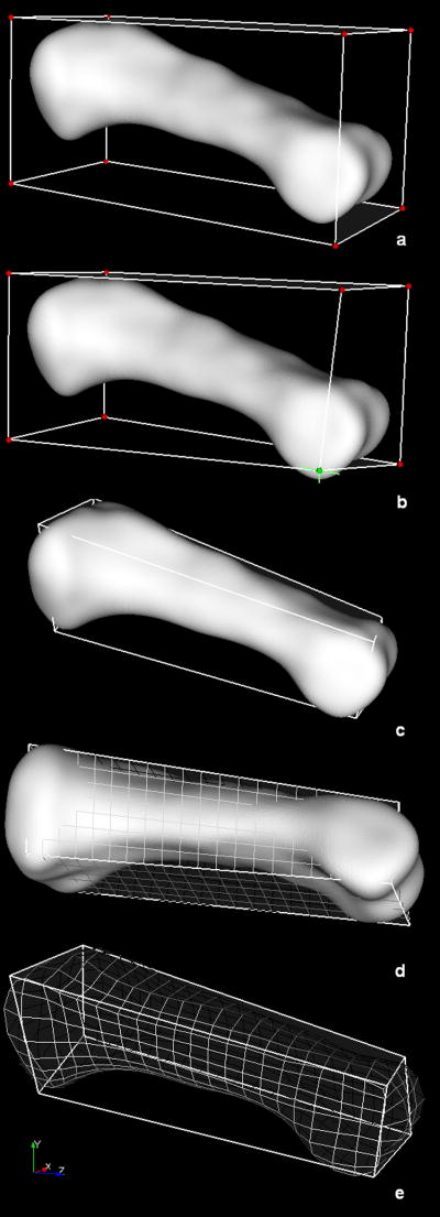
Central to the multiblock meshing technique is the block structure definition. Toward facilitating these definitions, we have developed an interactive building block technique, demonstrated in Figure 1. As illustrated, a single block may be sufficient (e.g., a phalanx bone of the hand). In such cases, the building block is automatically defined at the request of the operator, the dimensions of which are established directly from the bounds of the surface of interest (Figure 1a). Subsequent interactive manipulations may be performed on the building block to provide control over the resultant nodal projections (Figure 1b,c). Each building block is composed of mesh seeding arranged in rows, columns, and layers; the corresponding level of seed refinement is specified by the user (Figure 1d). The mesh seeds of the building block are then projected (via closest point projection) onto the surface of interest (Figure 1e). As a result, the mesh seeds are morphed to the bony surface as nodes, to lay the foundation for the FE mesh. Thereafter, Laplacian smoothing is performed on the surface nodes, followed by elliptic grid generation to compute the locations of the interior nodes. Once the nodal definitions are established throughout, the volume is filled with hexahedral elements. The aforementioned projection techniques have been extended to support multiple building blocks. Coupled with the ability to position each block face and vertex independently, the multiple building block technique results in a mesh of high quality elements.
Figure 1.
Closest point projection applied to a long bone (proximal phalanx) established via a single building block.
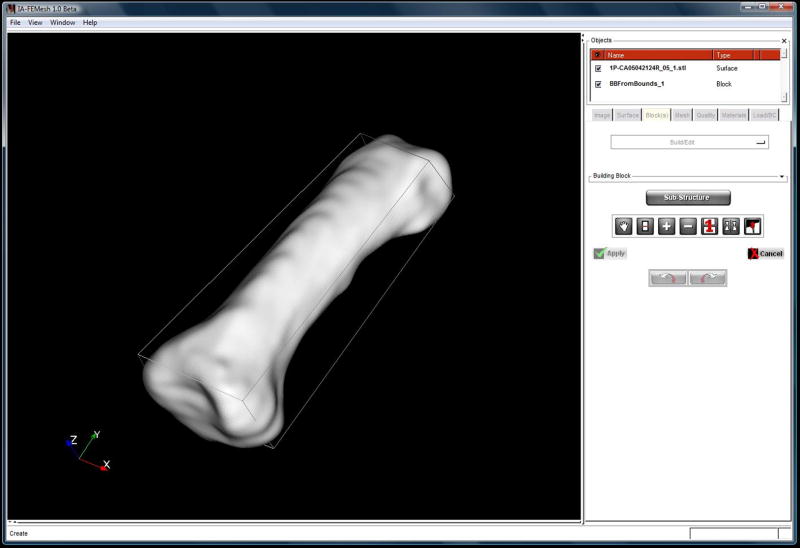
The software is written in C++, allowing IA-FEMesh to compile and run on common operating systems. Third-party open-source tools are used for some basic functionality, including the Image Registration and Segmentation Toolkit (www.itk.org), Visualization Toolkit (www.vtk.org) and KWWidgets (www.kwwidgets.org), for image handling, visualization and the graphical user interface, respectively (Figure 2).
Figure 2.
Screenshot of the IA-FEMesh graphical user interface.
2.1 The multiblock technique
As anatomic complexity increases, it imposes an increase in the required number of building blocks and hence attention to their spatial orientation; this in turn requires a means to readily manipulate the building block definitions. In order to make the multiblock technique user friendly, a number of interactive editing operations have been developed and incorporated into IA-FEMesh. The editing operations implemented to date include: (1) positioning individual vertices/edges/faces of a building block; (2) the subdivision of a building block, or series of building blocks; (3) the addition/deletion of a building block; and (4) mirroring and merging a building block structure. The following outlines each editing operation in detail.
2.1.1 Positioning, or repositioning, the individual vertices/edges/faces of a building block, or building blocks
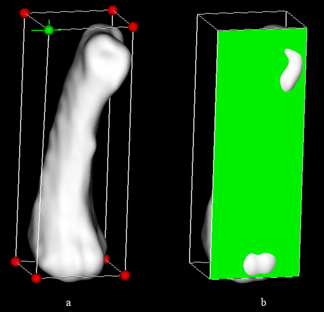
The premise behind altering the blocks from their original (and traditional) rectilinear configuration was to afford the user control over the placement of the projected nodes. Rather than tediously supply coordinates for the individual block vertices, the user may interactively reposition the block(s) by simply clicking on the object of interest (i.e., block vertex, edge, or face) and dragging it to the desired position. The mouse interactions have been facilitated, for example, by placing a sphere at each vertex of the building block (Figure 3a). By coupling the motion of each vertex with that of the associated sphere, the size/shape of the building block is adjusted based on the movement of the mouse. If a vertex is shared by multiple building blocks, a change in its position, will alter each block accordingly. Similarly, each external edge and face may be repositioned independently in space, thereby modifying the block structure (Figure 3b). Figure 1c illustrates an example of a building block repositioned so as to better conform to the shape of the given surface.
Figure 3.
Building block editing operations enable the individual (a) vertices and (b) faces to be repositioned for improved mesh definitions. Visual confirmation of the active element (vertex/face) is provided via a color change (i.e., green is indicative of an active element).
There are instances where it may be desirable to eliminate motion of a vertex, or a series of vertices, thereby prohibiting inadvertent manipulation of a given block definition. Consequently, the user is afforded the opportunity to assign such restrictions.
2.1.2 Subdividing a building block, or series of blocks
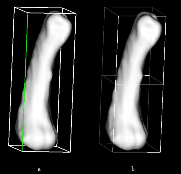
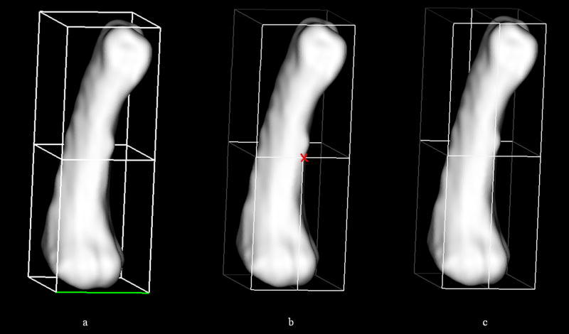
A building block may be divided in half by simply choosing the edge along which the block should be split. As a means of visual confirmation, the active edge is highlighted via a color change, and then bisected. The three edges parallel to the active edge are also bisected and vertices defined at the division points, thereby yielding two blocks from the pre-existing building block. Figure 4 illustrates a building-block prior to and following a prescribed subdivision.
Figure 4.
The subdivision of a building block box is accomplished by (a) selecting an edge (highlighted in green) along which to (b) bisect the block of interest.
As demonstrated, the division of a single building block is trivial. Now, consider a series of adjacent blocks (Figure 5a). If the logic above were applied, only the building block under consideration would be divided. As a result, in order to avoid hanging vertices (Figure 5b), the operator would be required to navigate through the structure and manually split all the blocks associated with the original block of interest. To circumvent this, special attention was given to the subdivision of a series of adjacent building blocks; the goal being to automate the recursive subdivision of the blocks sharing the bisected edges of the original, or parent, block. An algorithm was written to identify the neighboring building blocks sharing a common edge with the parent block. The parent block edges bisected during the division process subsequently denote the neighboring blocks for subdivision. These blocks then become parent blocks in the next level of recursion. This process continues until there are no neighboring blocks to subdivide.
Figure 5.
Special attention was given to subdividing (a) adjacent building blocks so as to avoid (b) hanging vertices (denoted by the red X). (c) The resulting four block structure.
2.1.3 Adding/Deleting a building block
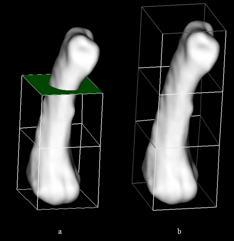
A new building block may be introduced to an existing building block structure by simply selecting the face to which the new block should be added (Figure 6a). The designated face is highlighted for visual confirmation and subsequently extruded a user specified distance along the face normal (Figure 6b). Conversely, a building block may be deleted by highlighting the block designated for deletion.
Figure 6.
Additional building blocks may be added to the structure by simply (a) choosing an existing face and (b) assigning a distance through which that new block should be extruded.
2.1.4 Mirroring building blocks and merging vertices
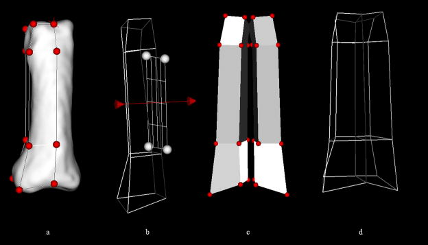
Provisions have been made to enable the user to take advantage of symmetry. A pre-existing building block, or series of blocks, may be mirrored (Figure 7) about a plane positioned relative to the blocks by the user. A plane, parallel to one of the coordinate planes (xy, xz, or yz), may be assigned automatically, or it may be interactively repositioned to a desired orientation. To reiterate, neighboring blocks share vertices. As a result, the vertices of the new structure must be merged with those from which it was mirrored. Consequently, the vertices of interest are moved into close proximity to one another and merged based on a radial tolerance assigned by the user.
Figure 7.
The user may take advantage of symmetry by (a) creating a block or series of blocks representing half of the structure and (b) mirroring the structure about a plane. (c) The vertices along the mirrored plane mirrored should be coincident. (d) As a result the vertices may be repositioned and merged.
2.2 Mesh density assignments
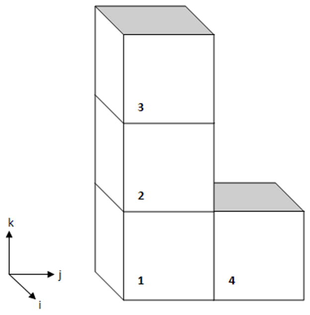
Once a building block, or series of blocks, has been established, the mesh density must be assigned throughout the model. At the level of an individual block, this is accomplished by simply specifying the number of divisions (i.e., elements), or the desired element length, along each coordinate axis of the block. As additional blocks are added the mesh density assignments become less trivial. Adjacent blocks share common nodes, thereby yielding a single unstructured mesh. In order for the resulting mesh to be continuous (node-to-node correspondence) at the interface of any two neighboring blocks, the number of divisions at a common edge (or face) should be equivalent. To automate the node-to-node correspondence, an extension of the algorithm used to split the building block structure has been implemented. Consider a single block; each coordinate axes has associated with it 4 parallel edges. The subdivision information is transferred within a block based on these associated parallel edges. As the connectivity between blocks is established, this information is transferred between blocks at the shared edges. The connectivity then propagates accordingly for each axis throughout the block structure. Table 1 summarizes the connectivity assignments required for propagating the assigned subdivisions throughout a four block structure, namely that illustrated in Figure 8. For example, the i-axis corresponding to block 1 will influence the divisions assigned to the i-axis of blocks 2, 3, and 4. In terms of the j-axis, block 1 controls the assignments for blocks 2 and 3, whereas the k-axis of block 1 influences only that of block 4. The connectivity matrix is established accordingly, incorporating the connectivity data for each block in the structure.
Table 1.
Logic for the connectivity between building blocks for automating the elemental subdivision assignments throughout the block structure
| Building Block | |||||
|---|---|---|---|---|---|
| 1 | 2 | 3 | 4 | ||
| 1 | i | ● | ○ | ○ | ○ |
| j | ● | ○ | ○ | ||
| k | ● | ○ | |||
| 2 | i | ○ | ● | ○ | ○ |
| j | ○ | ● | ○ | ||
| k | ● | ||||
| 3 | i | ○ | ○ | ● | ○ |
| j | ○ | ○ | ● | ||
| k | ● | ||||
| 4 | i | ○ | ○ | ○ | ● |
| j | ● | ||||
| k | ○ | ● | |||
Denotes a mesh seed assignment to a given axis (i,j,k) of a building block; ○ denotes the axes associated with each building block automatically assigned the subdivisions specified for the axis marked by ●
Figure 8.
Simplified block structure for depicting the connectivity logic outlined in Table 1.
2.3 Finite element mesh definition and improvement
The aforementioned subdivisions are used to establish the structured rectilinear mesh definitions for each building block. The nodes of the structured mesh are generated using isoparametric shape functions corresponding to a hexahedral element. Closest-point projection is used to morph the surface nodes of the rectilinear unstructured mesh onto the underlying bony surface of interest. Due to variations in the curvature of the underlying surface, the distribution of the projected nodes may be suboptimal. As a result, Laplacian[18] smoothing has been incorporated into IA-FEMesh as an option for smoothing the projected surface mesh. Laplacian smoothing acts to equalize the elemental edge lengths by adjusting the location of each node to the geometric center of its neighboring nodes. During this process, there is a tendency for the node being repositioned to move away from the surface. To ensure that the surface of the finite element mesh remains true to the desired underlying image based surface representation, the repositioned node is again projected onto the underlying surface using closest-point projection. Once the surface nodes are established, the user has the option of employing either elliptical or transfinite interpolation to compute the interior nodes; where, transfinite interpolation defines an algebraic coordinate transformation from the rectilinear grid(s) defined by the building block(s) onto the physical domain bounded by the surface, while elliptic grid generation is used to relax the initial grid iteratively using a series of elliptic partial differential equations, known as Poisson grid generation equations. Once the interior node definitions are established, the volume is filled with hexahedral elements.
Regardless of the meshing technique, a check of the resulting mesh quality is imperative; consequently, we have integrated a mesh quality viewer into the IA-FEMesh program suite. The objective is to make the mesh generation process more efficient by providing rapid, visual feedback to the user.
2.4 Mesh quality
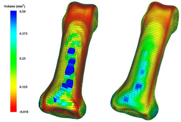
Our mesh quality application utilizes the open-source VERDICT library to analyze element quality according to several metrics that have been proposed in the literature[19–21]. Quality values are assigned per element and visualized using the VTK library. In addition to readily identifying zero-volume elements, the user has the option to choose between mesh quality metrics including: volume, Jacobian, scaled Jacobian, edge-ratio, and the Frobenius aspect. The tool supports the ability to display these metrics and to interact with the mesh in real time using the VTK pipeline architecture. Since datasets generally contain a large number of elements, interactive tools have been developed that allow the operator to isolate and examine both individual elements and element groupings. The user may dynamically position “cutting planes” within the dataset to expose internal elements. Furthermore, the elements may be scaled (via a shrink option) for improved visualization. Figure 9 illustrates the resulting mesh quality of a phalanx bone in terms of element volume, prior to and following mesh improvement via Laplacian smoothing. Prior to smoothing, there were 218 elements with zero, small, or negative volumes. These elements would ultimately preclude the mesh from being suitable for analysis. Following 5 iterations of Laplacian smoothing, however, the aforementioned element volumes were all satisfactorily increased (i.e., all element volumes > 0.00).
Figure 9.
Element quality (volume, mm3)) (a) prior to and (b) following 5 iterations of Laplacian smoothing.
2.5 Material property assignments
Subject specificity based on material definitions is facilitated by the fact that a linear relationship exists between digital CT scan data and the apparent density of bone[22]. Moreover, various models can be found in the literature for the relationship between bone density and elastic modulus. For the sake of generality, we have defined the elastic modulus according to the equation , where E is the elastic modulus, ρapp the apparent density, and a, b, and c the model parameters[23,24]. These parameters are treated as variables, introduced and tuned by the user according to the requirements of the specific problem. Long-term, the user will be able to specify the desired relationship between bone density and the elastic modulus.
Once a mesh has been generated there exists a direct correspondence between the model and the imaging data used to generate the bony surface definition. IA-FEMesh allows the user to assign element-wise material properties unique to each bone/specimen based on the CT number. The density information provided by the dataset is preserved by considering all of the CT voxels that fall within a given element. The user has the option of averaging the densities of each voxel contributing to an element, calculating the median density value, or assigning the maximum density contributing to the element. Thereafter, the elastic moduli are calculated on an element-by-element basis, thereby establishing the local stiffness.
Moreover, the user may control the range of variation of the elastic modulus for each material definition and assign a single elastic modulus to a set of elements, as opposed to assigning unique material definitions on an elemental basis. For example, material 1 may consist of elements with a modulus value in the range E1 ≤E ≤ Emax, while the range for material 2 takes the form E2 ≤ E < E1, and so on. This capability alleviates any restrictions imposed by some of the commercial finite element modeling packages with regard to a limited number of material definitions. Lastly, the ability to define a single constant tissue modulus, thereby assuming a homogenous material, has been incorporated as well.
2.6 Boundary and Loading Assignments
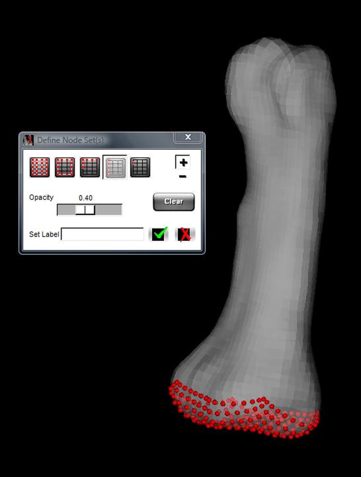
Interactive tools have also been implemented to identify nodes for boundary condition assignments. The user is afforded options for both single and multi-node selection. The single node selection is facilitated by highlighting the individual node as the mouse hovers and with the click of the mouse the node is added to a predefined set for assignment. Multi-node selection takes several forms. The user has the option of selecting the series of nodes associated with a face of a building block (Figure 10) or by selecting a group of nodes via an interactive rubberband box selection tool. The box selection tool may be used to select all of the nodes defining the continuum mesh within the selected volume, or limit the nodes to those on the surface of the mesh.
Figure 10.
Node selection capabilities include all nodes within the selected region; all surface nodes and surface nodes within view for a selected region; nodes associated with a building block face (illustrated); and single node selection.
2.7 Additional Mesh Definitions
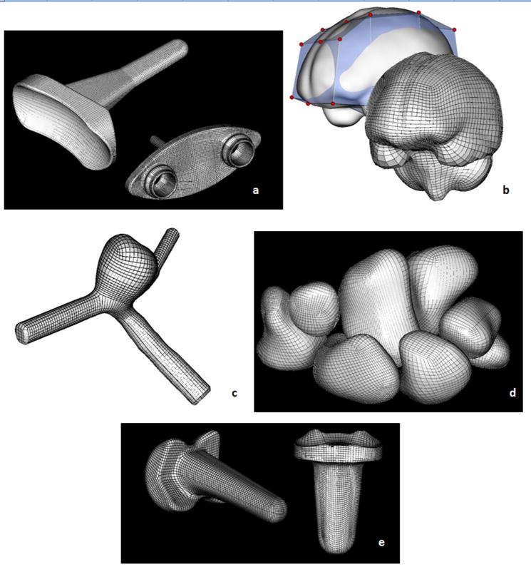
Figure 11 illustrates a variety of anatomic structures and replacements meshed via the multiblock meshing techniques available in IA-FEMesh. These mesh definitions represent structures whose surface representations were generated from a variety of sources: image-based (MR and CT) segmentations (i.e., the brain, an aneurysm, and carpal bones) as well as from CAD models (i.e, total joint replacements).
Figure 11.
Models created using IA-FEMesh (a) Universal 2™ Total Wrist implant, (b) the human brain, (c) an aneurysm, (d) the carpal bones, and (e) the Ascension PIP joint replacement.
3 Discussion
Mesh discritization plays a vital role in a finite element analysis. The exact type of discretization is determined by the numerical solution method. Moreover, the nature of the discretization influences the quality of the numerical solution (i.e., by the shape of the elements and the accurate approximation of the domain). An accurate approximation of the domain of interest depends not only on the mesh refinement[25], as determined by a convergence study, but on the accuracy of the method(s) used to segment the image datasets[26,27]. Both play a crucial role in the development of a valid mesh. Consequently, it is the responsibility of the operator to procure an appropriate surface definition, select a suitable element type, and perform a convergence study to establish the mesh refinement for a given analysis.
Commercial meshing tools are typically geared toward meshing engineering components with regular geometry and dimensions. Hence, they are often not suitable for meshing the irregularities of anatomic structures, especially when a mesh of hexahedral elements is of interest. Furthermore, the amount of time required to generate a mesh of high quality with traditional commercial software can be prohibitively expensive, oftentimes precluding their use in analyzing a large number of data sets. Moreover, a limited number of programs enable a mesh to be generated directly from imaging data, and those that do (e.g., Mimics (Materialise; Leuven, Belgium[28]) and ScanFE (Simpleware Ltd, United Kingdom)[29]), to our knowledge, rely on tetrahedral mesh generation. While free-form meshing schemes using tetrahedral elements are widely employed, it is well known that hexahedral elements would, in many cases, be more effective for analysis. Mesh generation consisting entirely of hexahedral elements, however, can be a daunting task which is amplified when irregular anatomic structures are considered.
In an effort to unencumber the meshing process, several automated meshing algorithms have been investigated. An assortment of three-dimensional techniques exists for the generation of tetrahedral, hexahedral, and voxel meshes. For example, Viceconti et al.[30] evaluated comparatively five different methods for automating mesh generation as applied to the human femur. The methods considered were: mapped mesh, which provides hexahedral elements through a direct mapping of a pre-defined mesh onto the geometry of interest; tetra mesh, which generates tetrahedral elements from a solid model of the object geometry (common with commercial codes); voxel mesh[31], which builds cubic 8-noded elements directly from CT data sets; and hexa mesh, that automatically generated hexahedral elements from a surface definition of the surface geometry. Each method exhibited its own set of advantages and limitations. The fact that the voxel meshing technique does not rely on any pre-processing of the dataset made it a favorable choice and, in some cases, perhaps the only viable option. The greatest drawback, however, is the resulting stairstep artifact at the surface, thereby making the technique impractical for contact modeling.
To address these meshing challenges, an interactive multi-block approach to mesh development has been implemented in our open-source software package, IA-FEMesh (note that this work is currently being integrated into Slicer3 the core tool of the National Alliance for Medical Image Computing (NA-MIC)). The mesh generation procedures are intuitive and are general enough to be applied to a range of skeletal structures. Novel mouse interactions allow the user to sculpt building block structures with ease. Thereafter, the building block structures act as the foundation for the subsequent steps of mesh seeding, mesh morphing, and interior node calculation. The benefit of this technique is apparent as the complexity of the structure(s) increases. The capability of IA-FEMesh to directly couple the mesh with image data facilitates not only the geometric definitions but the material property assignments as well. The quality viewer provides a means to evaluate the quality of the mesh prior to exporting it for analysis. If need be, smoothing may be invoked to improve the overall mesh discretization.
Efforts aimed at making the software intuitive and user friendly remain an emphasis. We are investigating means to further improve the resulting mesh quality via a variety of smoothing algorithms. As the complexity of the models increases, the majority of the mesh development time is expended creating the multiblock structure. As a result, we are investigating the feasibility of automating the building block definitions. In addition to the multiblock approach to meshing outlined herein, our long term goals for IA-FEMesh include integration of our voxel-based[32] and mapped meshing[33] techniques. Ideally, the modeling capabilities available in IA-FEMesh will enable the surgeon working alongside the engineer to plan patient-specific care using objective analysis-based tools. Thus, providing the means to better evaluate alternate surgical protocols and treatments, thereby contributing to improved surgical outcome.
Acknowledgments
The authors gratefully acknowledge financial support provided by awards R21EB001501 and R01EB005973 from the National Institute of Biomedical Imaging and Bioengineering, National Institutes of Health.
Footnotes
Conflict of Interest Statement
None Declared
Publisher's Disclaimer: This is a PDF file of an unedited manuscript that has been accepted for publication. As a service to our customers we are providing this early version of the manuscript. The manuscript will undergo copyediting, typesetting, and review of the resulting proof before it is published in its final citable form. Please note that during the production process errors may be discovered which could affect the content, and all legal disclaimers that apply to the journal pertain.
References
- 1.Brekelmans WAM, Poort HW, Slooff TJJH. A New Method to Analyse the Mechanical Behavior of Skeletal Parts. Acta Orth Scand. 1972;43:301–317. doi: 10.3109/17453677208998949. [DOI] [PubMed] [Google Scholar]
- 2.Huiskes R, Chao EY. A survey of finite element analysis in orthopedic biomechanics: the first decade. J Biomech. 1983;16(6):385–409. doi: 10.1016/0021-9290(83)90072-6. [DOI] [PubMed] [Google Scholar]
- 3.Huiskes R, Hollister SJ. From structure to process, from organ to cell: recent developments of FE-analysis in orthopaedic biomechanics. J Biomech Eng. 1993;115(4B):520–527. doi: 10.1115/1.2895534. [DOI] [PubMed] [Google Scholar]
- 4.Oonishi H, Isha H, Hasegawa T. Mechanical analyis of the human pelvis and its application to the artificial hip - by means of the three dimensional finite element. Journal of Biomechanics. 1983;16:427–444. doi: 10.1016/0021-9290(83)90075-1. [DOI] [PubMed] [Google Scholar]
- 5.Dooris AP, Goel VK, Grosland NM, Gilbertson LG, Wilder DG. Load-sharing between anterior and posterior elements in a lumbar motion segment implanted with an artificial disc. Spine. 2001;26(6):E122–129. doi: 10.1097/00007632-200103150-00004. [DOI] [PubMed] [Google Scholar]
- 6.Gilbertson LG, Goel VK, Kong WZ, Clausen JD. Finite element methods in spine biomechanics research. Crit Rev Biomed Eng. 1995;23(5–6):411–473. doi: 10.1615/critrevbiomedeng.v23.i5-6.20. [DOI] [PubMed] [Google Scholar]
- 7.Goel VK, Clausen JD. Prediction of load sharing among spinal components of a C5-C6 motion segment using the finite element approach. Spine. 1998;23(6):684–691. doi: 10.1097/00007632-199803150-00008. [DOI] [PubMed] [Google Scholar]
- 8.Goel VK, Kong W, Han JS, Weinstein JN, Gilbertson LG. A combined finite element and optimization investigation of lumbar spine mechanics with and without muscles. Spine. 1993;18(11):1531–1541. [PubMed] [Google Scholar]
- 9.Goel VK, Ramirez SA, Kong W, Gilbertson LG. Cancellous bone Young’s modulus variation within the vartebral body of a ligamentous lumbar spine - applications of bone adaptive remodeling concepts. 1995 doi: 10.1115/1.2794180. [DOI] [PubMed] [Google Scholar]
- 10.Huiskes R, Heck JV. Stresses in the femoral head-neck region after surface replacement. A three-dimensional finite element Analysis. Transactions of the Orthopaedic Research Society 1981 [Google Scholar]
- 11.Stokes IA, Laible JP. Three-dimensional osseo-ligamentous model of the thorax representing initiation of scoliosis by asymmetric growth. Journal of Biomechanics. 1990;23(6):589–595. doi: 10.1016/0021-9290(90)90051-4. [DOI] [PubMed] [Google Scholar]
- 12.Bornemann F, Erdmann B, Kornhuber R. Adaptive Multilevel Methods in Three Space Dimensions. Int J Num Meth Eng. 1993;36:3187–3203. [Google Scholar]
- 13.George PL. Automatic Mesh Generation. John Wiley & Sons; 1993. [Google Scholar]
- 14.Mitchell SA, Vavasis SA. Quality Mesh Generation in Three Dimensions. Proc 8th ACM Conf on Comp Geometry.1992. [Google Scholar]
- 15.Weatherill NP. Part II Unstructured Grids. In: Thompson JF, Soni BK, Weatherill NP, editors. Handbook of Grid Generation. CRC Press; Boca Raton, FL: 1999. pp. II–1. [Google Scholar]
- 16.Thompson JF. In: Part I Block-Structured Grids.in Handbook of Grid Generation. Thompson JF, Soni BK, Weatherill NP, editors. CRC Press; Boca Raton, FL: 1999. pp. I–12. [Google Scholar]
- 17.ABAQUS, SIMULIA, Dassault Systèmes, Providence, RI.
- 18.Field D. Laplacian smoothing and delaunay triangulations. Communications in Applied Numerical Methods. 1988;4:709–712. [Google Scholar]
- 19.Knupp PM. Achieving Finite element mesh quality via optimization of the Jacobian matrix norm and associated quantities. Part II - A framework for volume mesh optimization and the condition number of the Jacobian matrixt. Int J Numer Meth Engng. 2000;48:1165–1185. [Google Scholar]
- 20.Knupp PM. Algebraic Mesh Quality Metrics. Siam J Sci Comput. 2001;23(1):193–218. [Google Scholar]
- 21.Knupp PM. Algebraic mesh quality metrics for unstructured initial meshes. Finite Elements in Analysis and Design. 2003;39:217–241. [Google Scholar]
- 22.McBroom RJ, Hayes WC, Edwards WT, Goldberg RP, White AA. Prediction of vertebral body compressive fracture using quantitative computed tomography. Journal of bone and Joint Surgery. 1985;67A:1206–1214. [PubMed] [Google Scholar]
- 23.Carter DR, Hayes WC. Bone compressive strength and influence of density and strain rate. Science. 1976;194(4270):1174–1176. doi: 10.1126/science.996549. [DOI] [PubMed] [Google Scholar]
- 24.Carter DR, Hayes WC. The compressive behaviour of bone as a two-phase porous structure. Journal of Bone & Joint Surgery. 1977;1977(59A):954–962. [PubMed] [Google Scholar]
- 25.DeVries NA. A three-dimensional subject-specific computational study of the human hand and index-finger. The University of Iowa; 2007. [Google Scholar]
- 26.Gassman EE, Powell SM, Kallemeyn NA, DeVries NA, Shivanna KH, Magnotta VA, Ramme AJ, Adams BD, Grosland NM. Automated bony region identification using artificial neural networks: reliability and validation measurements. Skeletal Radiol. 2008;37(4):313–319. doi: 10.1007/s00256-007-0434-z. [DOI] [PubMed] [Google Scholar]
- 27.Ramme AJ, DeVries NA, Kallemyn NA, Magnotta VA, Grosland NM. Semi-automated Phalanx Bone Segmentation Using the Expectation Maximization Algorithm. J Digit Imaging. 2008 doi: 10.1007/s10278-008-9151-y. [Epub ahead of print] [DOI] [PMC free article] [PubMed] [Google Scholar]
- 28.Mimics, Materialise, http://www.materialise.com/materialise/view/en/92458-Mimics.html.
- 29.ScanFE, Simpleware, Ltd, http://www.simpleware.com/software/scanfe.php.
- 30.Viceconti M, Bellingeri L, Cristofolini L, Toni A. A comparative study on different methods of automatic mesh generation of human femurs. Medical Engineering and Physics. 1998;20:1–10. doi: 10.1016/s1350-4533(97)00049-0. [DOI] [PubMed] [Google Scholar]
- 31.Keyak JH, Meagher JM, Skinner HB, Mote CD. Automated three-dimensional finite element modelling of bone: a new method. Journal of Biomedical Engineering. 1990;12:389–397. doi: 10.1016/0141-5425(90)90022-f. [DOI] [PubMed] [Google Scholar]
- 32.Grosland NM, Brown TD. A Voxel-Based Formulation for Contact Finite Element Analysis. Computer Methods in Biomechanics and Biomedical Engineering. 2002;5(1):21–32. doi: 10.1080/10255840290032180. [DOI] [PubMed] [Google Scholar]
- 33.Grosland NM, Bafna R, Magnotta VA. Automated hexahedral meshing of human anatomical structures using deformable registration. Comput Methods Biomech Biomed Engin. 2008 Aug 7;:1. doi: 10.1080/10255840903065134. [Epub ahead of print] [DOI] [PubMed] [Google Scholar]


