Abstract
Recently, x-ray differential phase contrast computed tomography (DPC-CT) has been experimentally implemented using a conventional tube combined with gratings. Images were reconstructed using a parallel-beam reconstruction formula. However, parallel-beam reconstruction formulae are not applicable when the parallel-beam approximation fails. In this paper, we present a new image reconstruction formula for fan-beam DPC-CT. There are several novel features of the new image reconstruction formula: (i) when the scanning angular range of data acquisition is larger than π + γm (γm is the full fan angle), the entire field of view can be exactly reconstructed; (ii) when the scanning angular range is smaller than π + γm, a local region of interest (ROI) can be exactly reconstructed; (iii) it enables an exact reconstruction for a local ROI when the projection data are truncated at some view angles; (iv) it enlarges the imaging field of view when the detector is asymmetrically placed. In this last case, the data are truncated from every view angle. Numerical simulations have been conducted to validate the new reconstruction formula.
Phase contrast x-ray imaging and neutron imaging have a great potential in medical diagnosis and/or nondestructive industrial test. Historically, several methods have been proposed to extract phase information of an image object. These methods are differentiated from one another by measuring either the phase distribution (Bonse and Hart 1965, Momose et al 1996), the gradient of the phase distribution (Dilmanian et al 2000, Zhu et al 2005, Wang et al 2006, Momose et al 2006, Pfeiffer et al 2006a, 2006b, 2007) or the Laplacian of the phase distribution (Davis et al 1996, Wilkins et al 1996). Experimentally, these methods may impose different requirements on the coherence length of the source and different requirements on spatial resolution of the detector.
In the past several years, the differential phase contrast computed tomography (DPC-CT) imaging method has been successfully implemented using coherent x-rays generated by high-brilliance synchrotron radiations or low-brilliance sources. In these experiments, the measured projection data are essentially the refraction angles of the incident beams. In synchrotron radiation experiments, the distance from source to image object is often more than 100 m. In this case, the radiation beams can be well approximated as parallel beams. Thus, parallel beam absorption computed tomography (CT) image reconstruction formulae can be readily adapted to DPC-CT (Faris and Byer 1988, Huang et al 2006, Maskimenko et al 2005).
Most recently, an ingenious scheme was proposed to implement phase contrast imaging experiments and phase contrast CT (Pfeiffer et al 2006a, 2006b, 2007) for both hard x-rays and neutrons. In this new approach, the x-rays or neutron beams generated by a conventional source are first collimated by an absorption grating into many line sources. Within each line source, the beams are highly coherent in the direction perpendicular to the grating lines. Different line sources are mutually incoherent. This new coherent beam generation method has been combined with shear interferometry to measure the gradient of the phase distribution. By measuring the gradient of the phase distribution from many different view angles, the principles of conventional absorption x-ray CT have been applied to generate DPC-CT images, which is a display of the local distribution of the decrement δ(x, y, z) in the complex refractive index n = 1 − δ + iβ. One major advantage of this new method is that it makes compact x-ray DPC-CT systems feasible. It also overcomes the problem of limited flux due to the requirement of micro-focus tube in other phase contrast CT proposals (Davis et al 1996, Wilkins et al 1996).
Unlike the synchrotron beam lines, for a compact x-ray imaging system, we need to account for the beam divergence. For a given x-ray detector with square shape, the degree of divergence is determined by the spanned fan-angle/cone-angle which is given by the following formula:
| (1) |
where H is the width/height of the detector and D is the distance from the x-ray focal spot to detector distance. Therefore, when the source to detector distance D is very long, the diverging effect of the x-ray beams are negligible, this is often the case for synchrotron beam lines and also for the in-line holography phase contrast imaging method. In this case, the beams are well approximated as plane waves and a parallel-beam image reconstruction method is sufficiently good for image reconstruction in DPC-CT. However, using the new phase retrieval method (Pfeiffer et al 2006a, 2006b, 2007), the distance D is significantly reduced (160 cm in (Pfeiffer et al 2007)). Note that the effective detector size is limited by the available size of the third grating in the front of the detector, it is about 6 cm in (Pfeiffer et al 2007). Using these parameters, the divergence angle in (Pfeiffer et al 2007) can be estimated as
| (2) |
In this case, the parallel-beam approximation is still acceptable and the well-known parallel-beam image reconstruction method (Faris and Byer 1988, Huang et al 2006, Maskimenko et al 2005, Pfeiffer et al 2007, Engelhardt et al 2007, Weitkamp et al 2005) can be adapted to reconstruct DPC-CT images.
When a larger size image object is scanned with the same detector-to-source distance D, the divergence angle γm increases. The parallel-beam approximation is less and less accurate. When the divergence angle goes beyond about 5 degrees, it can been shown that the diverging nature of the data acquisition system is not negligible any more. In fact, if the size of the image object is doubled in the above estimation, the divergence angle is almost 5 degrees. Therefore, a divergent beam image reconstruction algorithm is desirable for this new DPC-CT data acquisition method. Otherwise, the image quality will be degraded significantly. In this paper, we present an image reconstruction formula for fan-beam DPC-CT which can be utilized to accurately reconstruct DPC-CT images at any fan angle.
Although a thorough analysis of the real data acquisition requires the incorporation of the wave nature of x-rays, it is convenient to use an effective model in ray optics to derive the image reconstruction algorithms. Therefore, for simplicity, the propagation of x-rays in a medium can be delineated using ray dynamics (Born and Wolf 1999):
| (3) |
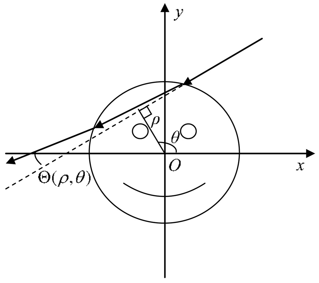
where s is the kinematic parameter of the ray, s⃗ is the tangent direction of the ray and ∇n is the gradient of the refractive index n = 1 − δ + iβ. Here, δ is the decrement of the real part of the object’s refractive index (for brevity, this will be referred to as the decrement index), while β describes the attenuation effect. Under the para-axial approximation (Kafri and Glatt 1990), an integration along the incident ray direction yields the refraction angle Θ. For clarity, we use a geometrical model shown in figure 1 to demonstrate how the refraction angle is related to the gradient of the refractive index. Using the notations in figure 1, we have the following relation:
| (4) |
Figure 1.
The geometric model for the refraction of x-rays.
The line integral in equation (4), Rδ(ρ, θ), is nothing but a Radon transform (Kak and Slaney 1988) of the decrement index along the incident ray direction, l, which is tilted from the x-axis by an angle θ (figure 1). Meanwhile, ρ is the distance from the origin to the straight line l. Thus, equation (4) dictates that the refraction angle is the first-order derivative of the Radon transform of the decrement index.
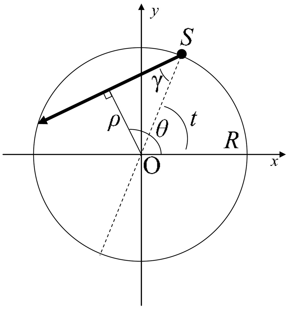
When the data are acquired using the fan-beam geometry as shown in figure 2, the total deflection angle Θ(ρ, θ) after the x-rays penetrate through the image object can be labeled by the angular position, t, of the x-ray tube and the angle, γ, between the incident ray direction and the iso-line (from the source to the rotation center). Namely, the same physical quantity can be labeled by two different pairs of coordinates (Qi and Chen 2007), (ρ, θ) and (t, γ), as
| (5) |
Figure 2.
A geometrical demonstration of the fan-beam data acquisition, where R is the radius of the scanning trajectory and S is the location of the source.
The transforms between the two pairs of variables are given as
| (6) |
In parallel-beam data acquisition, it has been shown that equation (4) can be directly inserted into the well-known Radon inverse formula to obtain the image reconstruction algorithm for DPC-CT (Huang et al 2006, Pfeiffer et al 2007, Qi and Chen submitted). In the fan-beam data acquisition case, we need to find a relation between the measurable Θ(t, γ) and the derivative of the line integrals Rδ(t, γ). Using the transforms in equation (6), it is easy to work out the partial derivatives of the line integrals Rδ(t, γ) with respect to variables t and γ:
| (7) |
| (8) |
Thus, the subtraction of the above partial derivatives yields the following important identity:
| (9) |
Equation (5) and Equation (4) have been utilized in this derivation. This important identity provides a new connection between the DPC-CT and absorption CT image reconstruction algorithms. In the following, we use this identity to derive a new image reconstruction algorithm for DPC-CT which enables accurate image reconstruction with truncated projection data.
Most recently, a new image reconstruction formula was derived for absorption CT (Zhuang et al 2004, Leng et al 2005, Noo et al 2004, Pan et al 2005). In this formula, the image is reconstructed by applying a one-dimensional Hilbert transform on an intermediate image, which was referred to as a backprojection image Q(x, y; x′, y). The backprojection image is defined as
| (10) |
where . The view angles t1(x, y) and t2(x, y) are determined by the intersections between the circular source trajectory and the horizontal straight line passing through the image point (x, y). Note that the corresponding projection angle γ in equation (10) is determined by the ray which is passing through the point (x′, y) from a given view angle t. Using identity (9), one can compute the backprojection image in DPC-CT as follows:
| (11) |
where there is no need to compute the derivatives of the measurable data Θ(t, γ) with respect to the variables t and γ. Using the backprojection image Q(x, y; x′, y), the image is then reconstructed using the following formula:
| (12) |
where the constant A should be larger than the radius of the imaging field of view but smaller than the radius of the scanning trajectory R. The constant C in the above equation is determined by the fact that the image values δ(x, y) are zero outside the image support. Therefore, if we suppose point (xc, yc) is a point outside the image support, then we have
| (13) |
Therefore, equation (11)–equation (13) represent a new image reconstruction method for fan-beam DPC-CT. The formulae provide a means to reconstruct the decrement of the real part of the refractive index via two numerical steps:
Step 1. Backproject the measured projection data Θ(t, γ) to obtain a backprojection image Q(x, y; x′, y) using equation (11).
Step 2. Filter the backprojection image along the x-direction using a Hilbert kernel using equation (12).
Before we proceed, several comments on the new image reconstruction formula are in order. First, to compute the value of a point in the backprojection image, we only need one data point from each view angle. Thus, there is no need to require the detector to be large enough to cover the entire image object. In contrast, in the conventional filtered backprojection image reconstruction method (Pfeiffer et al 2007, Huang et al 2006), in order to guarantee an accurate filtration of the data acquired at each view angle, the data should not be truncated. Second, for different image points, the angular ranges, [t1(x, y), t2(x, y)], for the backprojection image may be different. An exception is that the angular range is the same for all of the points on the chord . This flexibility opens up a new possibility to exactly reconstruct a local region of interest (ROI) with data acquired in a super-short angular range (the range less than π + γm). Third, using the first feature, we may enlarge the imaging field of view by asymmetrically positioning the detector.
In the following, numerical simulations were conducted to demonstrate these new features using two different phantoms. Both of them consist of a uniform elliptical disc, and two inserted uniform circular discs. The length of the semi-major and semi-minor axes of the elliptical disc are 1.0 and 0.5, respectively. The radius of the discs is 0.16. In the first phantom, the decrement index for the ellipse is 0.5 × 10⁻⁶, and the decrement index for the two circular discs is 1.0 × 10⁻⁶. The two circular discs are positioned along the major-axis of the ellipse. In the other phantom, the decrement index for the ellipse is identical to the first phantom, but the decrement index for the two discs are 0 and 1.0 × 10⁻⁶, respectively. The two discs are positioned along the minor-axis of the ellipse. In our numerical simulations, the refraction angles are analytically calculated using Snell’s law (Born and Wolf 1999). The radius of the source trajectory was 4.0 and the view sampling rate was . A curved detector was utilized and the detector sampling rate was . In the case of no data truncation, it is easy to see that the fan angle should be larger than 30°. The display window used here for the image presentation was [0.1, 1.1] × 10−6. The horizontal direction was selected as the direction of the finite Hilbert transform.
Case 1. Short scan data acquisition mode
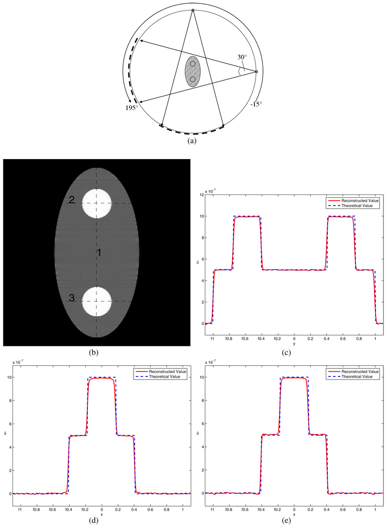
In the first numerical experiment, we demonstrate that an angular range of π + γm[−15°, +195°] is sufficient for an accurate reconstruction of the entire image object provided that there is no data truncation. Namely, we assume that the detector is sufficiently large to cover the entire image object from all view angles.
The reconstructed image and the corresponding plots of image intensity along three different lines are given in figure 3. One can clearly see that the reconstructed values match the theoretical values well.
Figure 3.
Simulation for case 1. Part (a) shows the diagram for the scan configuration, in which the view angle range equals 180° plus the fan angle 30°. The shaded area shows the part of the object which can be accurately reconstructed based on the data-sufficiency condition. Part (b) is the reconstructed image, and parts (c)–(e) are the profiles for the three lines in (b), respectively. The entire phantom is accurately reconstructed.
Case 2. Super-short scan data acquisition mode
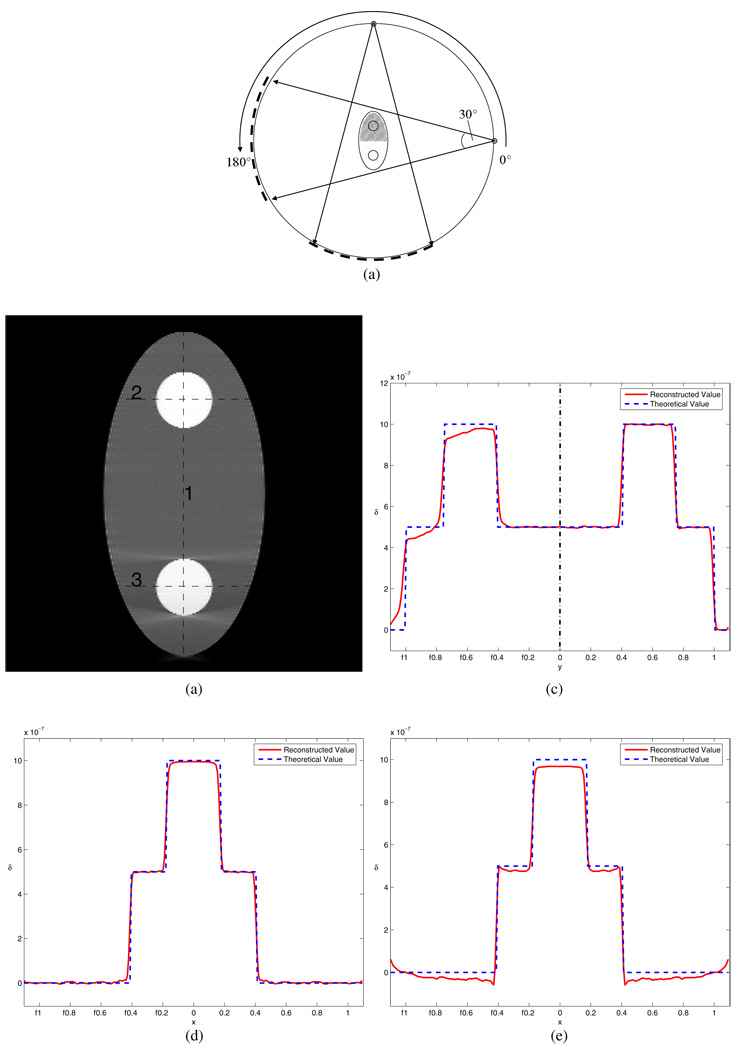
In the second numerical experiment, we demonstrate the capability of the new image reconstruction to exactly reconstruct a local region of interest even if the acquired data range is smaller than π + γm. In this case, the data acquisition is over the angular range of [0°, 180°]. Although we do not have enough data to exactly reconstruct the entire image, it is possible to reconstruct part of the image object without artifacts. In figure 4, it is shown that the upper part of the image object was accurately reconstructed using the new algorithm while the reconstruction of the lower part of the image object is inaccurate due to the data insufficiency. The boundary is marked by a vertical dashed line in figure 4(c). The left portion of the plot corresponds to the lower half of the reconstructed image and the right portion of the plot corresponds to the upper part of the reconstructed image.
Figure 4.
Simulation for case 2. Part (a) shows the diagram for the scan configuration, in which the view angle range equals 180°. The shaded area shows the part of the object which can be accurately reconstructed based on the data sufficiency condition. Part (b) is the reconstructed image, and parts (c)–(e) are the profiles for the three lines in (b), respectively. The upper half of the phantom is accurately reconstructed, although the lower half is not.
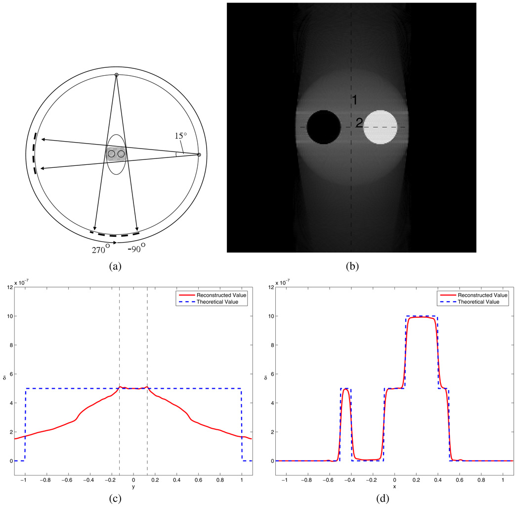
Case 3. Local ROI reconstruction with data truncation
In the third numerical experiment, we assume that the detector is not large enough to cover the entire image object for some view angles. However, it is sufficiently large to cover the entire image object at some other view angles (figure 3). For the given phantom, we selected the size of the detector such that the subtended fan angle is only 15° and the detector is symmetrically placed with respect to the rotation iso-center. In this case, we expect that the central ROI can be accurately reconstructed, but the peripheral regions cannot be reconstructed accurately due to the data insufficiency. In figure 5, we present the reconstructed image and the corresponding plots of image values along two different straight lines. As shown in figure 5(c), the portion between two vertical and dashed lines is accurately reconstructed while the peripheral portions have significant signal drop. The results clearly demonstrate the accuracy of the reconstruction.
Figure 5.
Simulation for case 3. Part (a) shows the diagram for the scan configuration, in which the fan angle is only 18°, in sufficient to cover the object in each view angle. The shaded area shows the part of the object which can be accurately reconstructed based on the data sufficiency condition. Part (b) is the reconstructed image, and parts (c) and (d) are the profiles for the two lines in (b), respectively. The central part of the phantom is still able to be accurately reconstructed.
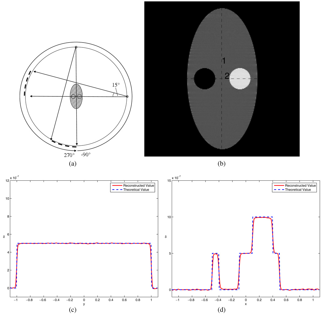
Case 4. Enlarged field of view (FOV) imaging
In the last numerical experiment, we present a method to double the image field of view by using the new algorithm. In this case, we use exactly the same data acquisition setup as in the case 3 except that the detector is shifted to the one side as shown in figure 6(a). In this case, it is easy to see that the data are truncated at every view angle. When the angular range is [0, 2π], we demonstrate that the entire image object may be accurately reconstructed using the new algorithm presented in this paper. This numerical example demonstrates a new way to image a relatively large object using a small detector. This provides a practical means to enlarge the image FOV in DPC-CT.
Figure 6.
Simulation for case 4. Part (a) shows the diagram for the scan configuration, in which the detector could only cover half of the phantom while the view angle range is 360°. The shaded area shows the part of the object which can be accurately reconstructed based on the data sufficiency condition. Part (b) is the reconstructed image, and parts (c) and (d) are the profiles for the two lines in (b), respectively. The whole phantom is able to be accurately reconstructed.
In conclusion, a new image reconstruction formula for DPC-CT is presented in this paper. Numerical simulations have been presented to validate the reconstruction formula. In this new formula, the image reconstruction is performed in two steps. The first step is to compute the backprojection image and the second step is to filter the backprojection image to obtain the final image. The key feature of the new image reconstruction algorithm is its capability to handle the data truncation problem. This capability is of practical importance in DPC-CT. Namely, even if we only have a small detector, we may be able to image a large object by shifting the detector to one side.
Acknowledgments
The work is partially supported by a grant from National Institutes of Health with grant number R01-EB005712.
Footnotes
Online at stacks.iop.org/PMB/53/1015
Note added in Proof. During the revision of this manuscript, a parallel-beam version of the algorithm presented in this paper has been brought to our attention by one of the reviewers for diffraction enhanced imaging (DEI) [25].
References
- Bonse U, Hart M. An x-ray interferometer with long interfering beam paths. Appl. Phys. Lett. 1965;7:99–101. [Google Scholar]
- Born M, Wolf E. Principles of Optics. 7th edn. Cambridge: Cambridge University Press; 1999. [Google Scholar]
- Davis TJ, Gao D, Gureyev TE, Stevenson AW, Wilkins SW. Phase-contrast imaging of weakly absorbing materials using hard x-rays. Nature. 1996;373:595–598. [Google Scholar]
- Dilmanian FA, Zhong Z, Ren B, Wu XY, Chapman LD, Orion I, Thomlinson WC. Computed tomography of x-ray index of refraction using the diffraction enhances imaging method. Phys. Med. Biol. 2000;45:933. doi: 10.1088/0031-9155/45/4/309. [DOI] [PubMed] [Google Scholar]
- Engelhardt M, Baumann J, Schuster M, Kottler C, Pfeiffer F, Bunk O, David C. High-resolution differential phase contrast imaging using a magnifying projection geometry with a microfocus x-ray source. Appl. Phys. Lett. 2007;90:224101. doi: 10.1063/1.2786273. [DOI] [PubMed] [Google Scholar]
- Faris GW, Byer RL. Three-dimensional beam deflection optical tomography of a supersonic jet. Appl. Opt. 1988;27:5202–5213. doi: 10.1364/AO.27.005202. [DOI] [PubMed] [Google Scholar]
- Huang ZF, Kang KJ, Li Z, Zhu PP, Yuan QX, Huang WX, Wang JY, Zhang D, Zhu AM. Direct computed tomographic reconstruction for directional-derivative projections of computed tomography of diffraction enhanced imaging. Appl. Phys. Lett. 2006;89:041124. [Google Scholar]
- Kafri O, Glatt I. The Physics of Moire Metrology. New York: Wiley-Interscience; 1990. [Google Scholar]
- Kak AC, Slaney M. Principles of Computerized Tomographic Imaging. New York: IEEE; 1988. [Google Scholar]
- Leng S, Zhuang T-L, Nett BE, Chen G-H. Exact fan-beam reconstruction algorithm for truncated projection data acquired from an asymmetric half-size detector. Phys. Med. Biol. 2005;50:1805–1820. doi: 10.1088/0031-9155/50/8/012. [DOI] [PubMed] [Google Scholar]
- Maskimenko A, Ando M, Hiroshi S, Yuasa T. Computed tomographic reconstruction based on x-ray refraction contrast. Appl. Phys. Lett. 2005;86:124105. [Google Scholar]
- Momose A, Takeda T, Itai Y, Hirano K. Phase-contrast x-ray computed tomography for observing biological soft tissues. Nature Med. 1996;2:473–475. doi: 10.1038/nm0496-473. [DOI] [PubMed] [Google Scholar]
- Momose A, Yashiro W, Takeda Y, Suzuki Y, Hattori T. Phase tomography by x-ray talbot interferometry for biological imaging. Japan. J. Appl. Phys. 2006;45:5254–5262. [Google Scholar]
- Noo F, Clackdoyle R, Pack JD. A two-step Hilbert transform method for 2D image reconstruction. Phys. Med. Biol. 2004;49:3903–3923. doi: 10.1088/0031-9155/49/17/006. [DOI] [PubMed] [Google Scholar]
- Pan X, Zou Y, Xia D. Image reconstruction in peripheral and central regions-of-interest and data redundancy. Med. Phys. 2005;32:673–684. doi: 10.1118/1.1844171. [DOI] [PubMed] [Google Scholar]
- Pfeiffer F, Grunzweig C, Bunk O, Frei G, Lehmann E, David C. Neutron phase imaging and tomography. Phys. Rev. Lett. 2006a;96:215505. doi: 10.1103/PhysRevLett.96.215505. [DOI] [PubMed] [Google Scholar]
- Pfeiffer F, Weitkamp T, Bunk O, David C. Phase retrieval and differential phase-contrast imaging using polychromatic hard x-rays. Nature Phys. 2006b;2:258. [Google Scholar]
- Pfeiffer F, Kottler C, Bunk O, David C. Hard x-ray phase tomography with low-brilliance sources. Phys. Rev. Lett. 2007;98:108105. doi: 10.1103/PhysRevLett.98.108105. [DOI] [PubMed] [Google Scholar]
- Qi Z, Chen G-H. Direct image reconstruction algorithm via filtered backprojection for differential phase contrast computed tomography. J. X-ray Opt. Instrum. submitted. [Google Scholar]
- Qi Z, Chen G-H. A local region of interest image reconstruction via filtered backprojection for fan-beam differential phase-contrast computed tomography. Phys. Med. Biol. 2007;52:N417–N423. doi: 10.1088/0031-9155/52/18/N03. [DOI] [PubMed] [Google Scholar]
- Wang J, Zhu PP, Yuan Q, Huang A, Su H, Chen B, Hu T, Wu Z. Reconstruction of the refractive index gradient by x-ray diffraction enhanced computed tomography. Phys. Med. Biol. 2006;51:3391–3396. doi: 10.1088/0031-9155/51/14/007. [DOI] [PubMed] [Google Scholar]
- Weitkamp T, Diaz A, David C, Pfeiffer F, Stampanoni M, Cloetens P, Ziegler E. X-ray phase imaging with a grating interferometer. Opt. Exp. 2005;13:6296–6304. doi: 10.1364/opex.13.006296. [DOI] [PubMed] [Google Scholar]
- Wilkins SW, Gureyev TE, Gao D, Pagany A, Stevenson AW. Phase contrast imaging using polychromatic hard x-rays. Nature. 1996;384:335–338. [Google Scholar]
- Zhu PP, Wang JY, Yuan QX, Huang WX, Shu H, Gao B, Hu TD, Wu ZY. Computed tomography algorithm based on diffraction-enhanced imaging setup. Appl. Phys. Lett. 2005;87:264101. [Google Scholar]
- Zhuang T-L, Leng S, Nett BE, Chen G-H. Fan-beam and cone-beam image reconstruction via filtering the backprojection image of differentiated data. Phys. Med. Biol. 2004;49:5489–5503. doi: 10.1088/0031-9155/49/24/007. [DOI] [PubMed] [Google Scholar]


