Abstract
We used conductive nanotube films as substrates with which we could systematically vary the conductance to see how this property affects neuronal growth. Here we show that nanotube substrates in a narrow range of conductivity promote the outgrowth of neurites with a decrease in the number of growth cones as well as an increase in cell body area, while at higher conductance these effects disappear.
Keywords: carbon nanotubes, graft co-polymers, neurons, conductive substrate, neurite outgrowth
Conductive substrates show much promise in biological applications such as for use as implants providing pathways to regenerate neuronal connections, or creating devices to stimulate and record from cultured neuronal networks 1. Nanotubes are a promising material that has already begun to be used in these applications 2. However, it is not clear how the conductivity of these materials can affect neurons that come into contact with them. We show that conductive nanotubes are biocompatible as substrates for neuronal growth and that the specific level of conductivity is important as it affects neuronal outgrowth. Further studies with conductive substrates should pay attention to the resistance of the substrate and in applications where changes in neuronal growth are unwanted high conductivity should be sought in materials.
The conductivity of carbon nanotubes depends on the molecular conformation of the carbon backbone 3 which can be modified by the addition of different functional groups. These nanotubes have several advantages as a conductive substrate over other conductive substrates such as polypyrrole (PPy). The conductivity of the nanotubes is stable in biological environments and will not degrade like PPy does as it oxidizes in aqueous solution 1. Nanotubes are also strong and flexible which makes them ideal as a substrate for implantation in tissue. We fabricated conductive single-walled carbon nanotubes (SWNTs) and added polyethylene glycol (PEG) to them 4 to make them soluble in aqueous solution which increases their biocompatibility and aids in fabrication of the substrate. The SWNT-PEG graft copolymer was prepared as described previously 5. Briefly, purified SWNTs with carboxylic acid groups, SWNT-COOH, (P3-SWNT, Carbon Solutions Inc., www.carbonsolutioon.com) were reacted with oxalyl chloride to prepare an acyl chloride intermediate, SWNT-COCl, which was then reacted with polyethylene glycol (PEG, MW=600 g mol−1) to form the SWNT-PEG graft copolymer.
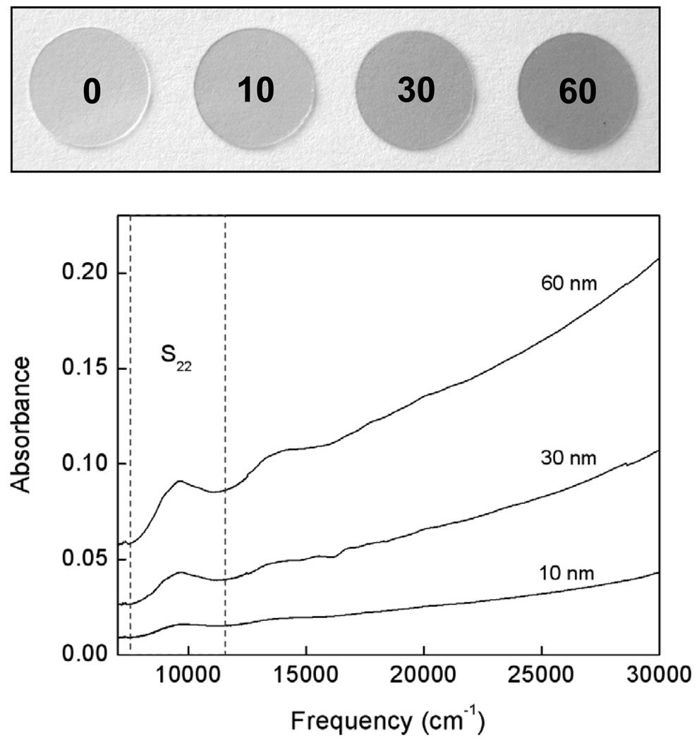
By spraying a film of these nanotubes onto hot glass coverslips we created retainable conductive substrates with which we could culture neurons. The SWNT-PEG were dispersed in double-deionized water by ultrasonication for 2 hours in a bath sonicator (VWR, Aquasonic 550HT) to obtain homogeneous dispersions with concentrations of ~0.05 mg/mL. The dispersions were sprayed with an airbrush onto round glass coverslips (12 mm in diameter) heated to ~ 160°C in order to allow the fabrication of uniform films. We could specifically control the conductivity of the substrate by varying the thickness of the nanotube film (Fig. 1). This allowed us to determine how the growth of neurons is affected at different levels of conductivity. These films were transparent and enabled us to study cells using epifluorescence microscopy. We made SWNT-PEG substrates 10 nm, 30 nm and 60 nm thick which had conductivities of 0.3, 28 and 42 S/cm, respectively. The thickness of the SWNT-PEG films was estimated from the UV-vis- near-infrared (NIR) spectra of the film. The NIR spectra of the SWNT-PEG films were recorded using a Varian CARY 5000 UV-vis-NIR spectrophotometer between frequencies of 7,000/cm and 30,000/cm. Absorbance of SWNT coated glass coverlips was background subtracted using absorbance of a bare coverslip. The mass of SWNT-PEG in the films was calculated from the Beer’s law for the intensity of the absorbance at 9750 cm−1, which corresponds to the second pair of singularities in the density of states of semiconducting SWNTs (S22) and the extinction coefficient of SWNT-PEG (ε = 9.2 Lg−1cm−1) 5. The thickness was then obtained assuming a bulk density of the SWNT-PEG (1.5 g cm−3) 6. The resistance of the films was measured in air at room temperature in a two-probe configuration using a Keithley 236 source measure unit. The contacts were attached to the films with silver paint. The SWNT-PEG film with a thickness of 10 nm has conductivity of 0.3 S/cm. The conductivity increases to 28 S/cm for the 30 nm film and it reaches a value of 42 S/cm for the SWNT-PEG film of 60 nm, which is close to the intrinsic conductivity of SWNT-PEG films (~60 S/cm). As a standard we used glass coverslips without SWNT films that were coated instead with the nonconductive compound, polyethylene imine (PEI), commonly used to coat glass coverslips to promote cell adhesion and growth 7–10.
Figure 1.
Image of SWNT-PEG coated glass coverslips (top), from left to right: PEI coated coverslip (standard; 0), 10nm thick nanotube film, 30nm thick, 60nm thick. Absorbance spectrum of the nanotube coated coverslips, background subtracted using absorbance from a bare coverslip. The near-infrared (NIR) absorption spectra of the SWNT-PEG films with thickness of 10 nm, 30 nm and 60 nm are shown in the graph. second interband transition of the semiconducting SWNTs, S22, is illustrated with dashed lines and is an indication of the purity of the nanotube films.
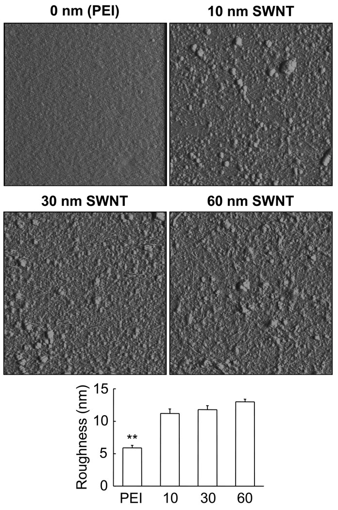
Previous studies suggested that substrate qualities play a role in the process of growth cone motility and neurite branching 11, 12. Consequently, we used Atomic Force Microscopy (AFM) to characterize the surface of PEI and SWNT-PEG films that were deposited onto glass coveslips (Fig. 2). For AFM experiments we argon dried the sample prior to acquisition of images using a Nanoscope E (Digital Instruments, Santa Barbara, CA) and Si3N4 gold-coated cantilevers with integral tips (Veeco Nano Probes™ tips, Santa Barbara, CA) in contact mode at room temperature (20–24°C). Qualitative inspection of substrates using deflection mode (Fig. 2; images) indicated that PEI has a smoother appearance than SWNT-PEG films which displayed pronounced nano/microtexturing. To quantify surface roughness of the sample we analyzed height mode images each covering 5 µm × 5 µm areas of PEI and the various SWNT-PEG films. Average roughness (6 images for each sample), expressed as a root mean square of height, showed that the PEI surface is significantly smoother (Fig. 2, graph; one-way ANOVA, followed by Schefeé’s pot-hoc comparison; p<0.01) than the surface of the SWNT-PEG films. However, the surface roughness of the three different thicknesses of SWNT films was similar (Fig. 2, graph; one-way ANOVA; p(2,15) = 0.12). Thus, PEI differs from SWNT-PEG films in terms of surface roughness and conductivity, while the SWNT films of different thickness/conductivity display similar surface roughness. Consequently, any effects on neuronal growth achieved on the various SWNT-PEG films result from their differences in conductivity, not surface roughness. However, when comparing the neuronal growth on various SWNT films to that of neurons grown on PEI, a standard substrate in neurobiology, any difference observed could be the outcome of either roughness and/or conductance.
Figure 2.
SWNT-PEG films of various thickness display similar surface roughness, PEI has much smoother surface. Deflection mode AFM images (5 µm × 5 µm) of PEI coated glass coverslips (0 nm) and glass coverslips coated with SWNT-PEG films thicknesses of 10 nm, 30 nm and 60 nm. Scanning rate, 2 Hz; imaging force ~ 1nN. Graph shows the analysis of surface roughness generated from height mode AFM images. Bars represent means ± standard errors of means; 6 images for each substrate. Asterisks indicate a significant difference in PEI measurement when compared to SWNT-PEG films (one-way ANOVA followed by Schefeé’s pot-hoc comparison;**p<0.01).
Hippocampal neurons from newborn rats were cultured on these substrates for 3 days to allow for adequate growth, at which point their growth and morphology were assessed. Hippocampal neuronal cultures were prepared from 0- to 2- day-old Sprague-Dawley rats using previously described procedures 7–10, 13. Briefly, following treatment with papain and trituration of hippocampal tissue, the cell suspension was applied onto the prepared nanotube-coated coverslips or coverslips coated with poly-ethylene imine (PEI; 1 mg/mL) that had been placed into culture dishes. After 3 hours of incubation to allow for neuronal adhesion, fresh culture medium (pH=7.35), consisting of minimum essential medium supplemented with fetal bovine serum (10% v/v; Hyclone), Mito+ serum extender (0.1% v/v, Collaborative Biomedical Products), D-glucose (20 mM), L glutamine (2 mM), sodium pyruvate (1 mM), penicillin (100 IU/mL), streptomycin (100 µg/mL) and sodium bicarbonate (14 mM), was applied to the dishes. Cultured cells from three independent cultures were then maintained in a humidified 5%CO2/95% air incubator at 37°C for 3 days until being imaged.
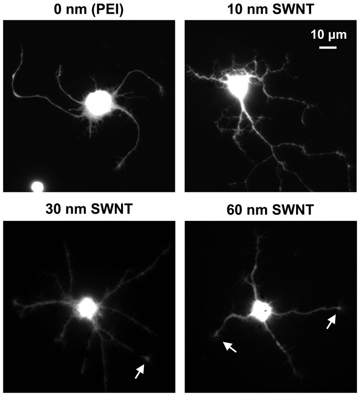
To study how the conductivity of the substrate affected the growth of neurons we labeled the cells with calcein. This fluorescent dye is retained within living cells and labels the cytoplasm revealing the shape of the neuron and all its processes (Fig. 3). Neurons were loaded with the acetoxymethyl ester of calcein (1µg/ml, Molecular Probes) for 15 minutes at room temperature. The ester’s dispersion in aqueous medium was aided by 0.025% Pluronic F-127 (Molecular Probes). After wash, the vital dye was permitted to de-esterify for 15 minutes at room temperature in normal external solution before imaging. The calcein labeling of cells on the different substrates revealed that the conductive substrates did not appear to affect cell viability.
Figure 3.
Chemically-functionalized conductive SWNT substrates permit neuronal survival and neurite outgrowth as shown by the ability of cells to retain the vital dye, calcein. Fluorescent images of live neurons grown on PEI coated coverslips and SWNT-PEG films of varying conductivity. Arrows indicate growth cones. Scale bar, 10 µm.
Labeled neurons were identified by their morphology using differential interference contrast (DIC) and fluorescence microscopy. Coverslips containing cultured neurons were mounted into a recording chamber filled with normal external solution composed of (in mM): NaCl (140), KCl (5), CaCl2 (2), MgCl2 (2), glucose (5), and Hepes (10) (pH=7.4). We examined neurons at room temperature (20–24° C) by using a microscope (Nikon TE300) equipped with DIC and epifluorescence illumination (xenon arc lamp; 100 W). Visualization was achieved using a standard FITC/fluorescein filter set (Chroma Technology Corp.) and a 60× Plan Apo objective. We used a CoolSNAP®-HQ cooled, charge-coupled device (CCD) camera (Roper Scientific Inc.) driven by V++ imaging software (Digital Optics Ltd., Auckland, New Zealand) to acquire images. To reduce photo-bleaching we inserted neutral density filters and an electronic shutter (Vincent Associates, Rochester, NY) that was controlled by software in the excitation pathway.
Neurons were identified based on their morphological features using differential interference contrast (DIC) and fluorescence microscopy. This method of identification has previously been confirmed as reliable by labeling with the neuron-specific markers: anti-β-tubulin III, neuron-specific enolase, and the c-fragment of tetanus toxin 7–10. For neurons that extended processes beyond the field of view multiple images were acquired and merged together using Adobe Photoshop CS2 (Adobe Systems Inc., San Jose, CA). Neuronal morphological characteristics were quantified using the Neurite application module of Metamorph imaging software ver. 6.1 (Molecular Devices, Chicago, IL).
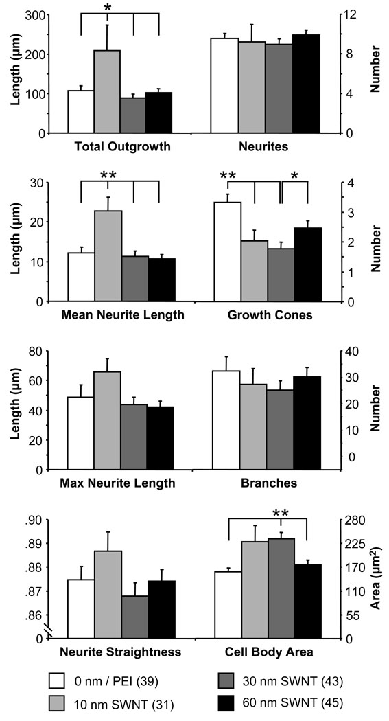
The conductive nanotube substrates we created could, indeed, be used to electrically stimulate or record from cells, but the effect of electrical stimulation on the growth of neurons has been well characterized 14. However, how the passive quality of conductivity of the substrate neurons are grown upon affects their growth has not been studied in a systematic manner. We looked at several measurements of neuronal growth to see how conductivity played a role (Fig. 4). These characteristics provide an indication of the potential for neuronal growth, interconnectivity and synapse formation. The total number of processes, neurites originating from the cell body, for each neuron remained the same regardless of the conductivity of the substrate (Fig.4, top; one-way ANOVA, p(3,150) = 0.08). The total outgrowth, the summed length of all processes and their branches, of each neuron was significantly greater in neurons grown on the 10 nm thick SWNT-PEG films than coverslips coated with non-conductive smoother PEI (Fig.4, top; Fisher’s LSD test, p < 0.05). However on the thicker films (30 nm and 60 nm) with higher conductivity, but comparable roughness to the 10 nm SWNT-PEG film, there was no difference in neurite outgrowth from standard. This indicates that a certain SWNTPEG conductance (0.3 S/cm) could promote neurite outgrowth as compared to other SWNT films (Fig.4, top). Similar findings have been shown with non-neuronal fibroblast and endothelial cells grown on PPy coated polyester fabrics of various conductivity 15. In this case, cell adhesion, migration, density and protein expression was highest on substrates of intermediate conductance (0.43 – 0.9 S/cm) while higher levels impaired cell viability. Quite contrary, here neurons grown on high conductance substrates survived just fine. We have shown previously that soluble PEG-SWNTs can affect neuronal growth by altering intracellular Ca2+ dynamics 10 and/or endocytosis 9. However, these effects increased in a dose-dependent manner and the reduction in effect on thicker films here argues against the possibility that nanotubes are dispersing out of the substrate and interacting with neurons in this manner. Also, the visual (grey) appearance of coverslips coated with nanotube films have not changed during culturing conditions.
Figure 4.
Parameters of cell growth and morphology for neurons grown on SWNT substrates of varying conductivity. Bars represent means ± standard errors of means. Numbers in parenthesis indicate the number of neurons studied in each condition. Asterisks indicate a significant difference in measurements (one-way ANOVA followed by Fisher’s LSD test; *p < 0.05,** p < 0.01).
Since the total outgrowth of the neurites had increased but the number of processes remained the same then the length of each process should be increased, which is what we found when we measured process length. The mean process length was significantly longer in neurons grown on the 10 nm films compared with control (Fig.4, second row; Fisher’s LSD test, p < 0.01). The higher conductance substrates (30 nm and 60 nm SWNT films) showed no difference in process length from the non-conductive PEI standard, regardless that the surface of SWNT films show significantly different roughness from PEI. The maximum process length of each neuron was not significantly affected by the conductivity of the substrate (Fig.4, third row; one-way ANOVA, p(3,150) = 0.13) nor were the number of branches on all processes of each neuron altered (Fig.4, third row; one-way ANOVA, p(3,150) = 0.58). The straightness of the neurites, measured as a ratio of the distance between the origin and the end of a process over the total length of the process, was not affected by the conductivity of the substrate (Fig.4, fourth row; one-way ANOVA, p(3,150) = 0.51). There was an increase in the average area of the neuron cell body as conductivity increased, showing a trend at 0.3 S/cm, and with a statistical significance at 28 S/cm when compared to standard and to 42 S/cm (Fig.4, bottom row; Fisher’s LSD test, p < 0.01), while decreasing to the level of standard PEI at higher conductivity (42 S/cm). Neurons grown on the smoother PEI had a significantly higher number of growth cones than those grown on 10 nm and 30 nm SWNT films, but not higher than those grown on 60 nm SWNT films (Fig.4, second row; Fisher’s LSD test, p < 0.01). Since PEI has a much smoother surface than SWNT films, it appears that either the roughness and/or conductivity could cause this effect. However, there was a significantly higher number of growth cones on neurons grown on 60 nm SWNT films when compared to measurements on 30 nm SWNT films. Since the roughness of these two conductive films is similar, it appears that the higher conductance caused an increase in the of number of growth cones, perhaps by rescuing some of the negative effects of roughness on the number of growth cones.
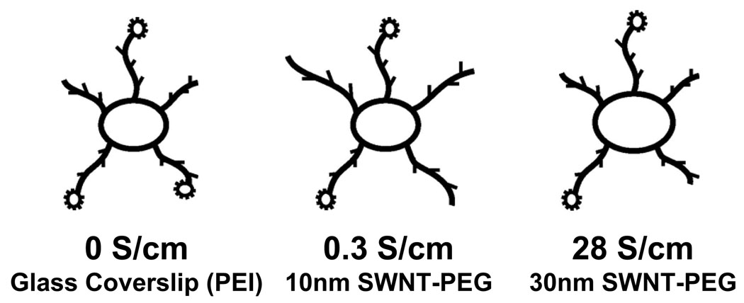
In this study we investigated how the conductivity of the substrate affected neuronal growth and morphology and more so, how substrates in a range of specifically designed conductivities affected this growth. These results indicate that a SWNT-PEG substrate in a narrow range of conductivity can promote neuronal growth and neurite outgrowth (Scheme 1). As conductivity increases beyond this range these effects on (out)growth are diminished. This finding may explain the differences seen by other groups where some find increased growth on conductive PPy substrates 16, 17 and others see reduced or no effect 18, 19, or only see an increase in growth when current is applied to the substrate 20, 21. Most studies do not report on the resistance of the substrate so it is hard to compare results from one to another, however. Studies with conductive substrates have mostly investigated how electric fields applied through the substrate affect neuronal growth 22. How the passive property of conductivity in the substrate can affect neuronal growth has not been characterized. While the reasons for the improved neurite outgrowth we observed on low conductance SWNT-PEG films were not clear, similar findings with fibroblast and endothelial cells attributed the improved growth characteristics at intermediate conductance to modification of ionic transport across the cell membrane 15. Similar mechanisms to those postulated to be behind the improved neuronal growth due to applied electric fields 20 may contribute to the improved growth on passively conductive films such as: membrane or extracellular matrix protein conformational changes23, increased depolarization or hyperpolarization, or enhancement of protein synthesis24.
Scheme 1.
Drawing summarizing the effects of the conductivity of SWNT substrates on neuronal growth and neurite outgrowth.
Conductive substrates have been shown to be advantageous for use as neuronal implants in vivo, supporting neuronal growth and displaying less gliosis than nonconductive Teflon implants when inserted into rat cortex 25. Since nanotubes are stronger and more flexible than PPy and toxicity does not appear to be a concern in systemic applications 26, scaffolds of conductive nanotubes would be ideal for applications as neural prostheses. In this respect, coating of standard metal electrodes with carbon nanotubes has been recently employed in brain recordings 27.
Acknowledgments
This work was supported by grants from Department of Defense/Defense Microelectronics Activity (Award No. DOD/DMEA-H94003-06-2-0608) and the National Institute of Mental Health (Grant R01 MH 069791).
References
- 1.Ateh DD, Navsaria HA, Vadgama P. J R Soc Interface. 2006;3(11):741–752. doi: 10.1098/rsif.2006.0141. [DOI] [PMC free article] [PubMed] [Google Scholar]
- 2.Malarkey EB, Parpura V. Neurodegener Dis. 2007;4(4):292–299. doi: 10.1159/000101885. [DOI] [PubMed] [Google Scholar]
- 3.Bekyarova E, Ni Y, Malarkey EB, Montana V, McWilliams JL, Haddon RC, Parpura V. J Biomed Nanotechnol. 2005;1:3–17. doi: 10.1166/jbn.2005.004. [DOI] [PMC free article] [PubMed] [Google Scholar]
- 4.Zhao B, Hu H, Haddon RC. Adv. Func. Mater. 2004;14:71–76. [Google Scholar]
- 5.Zhao B, Hu H, Perea D, Haddon RC. J. Am. Chem. Soc. 2005;127:8197–8203. doi: 10.1021/ja042924i. [DOI] [PubMed] [Google Scholar]
- 6.Bekyarova E, Itkis ME, Cabrera N, Zhao B, Yu AP, Gao JB, Haddon RC. Journal of the American Chemical Society. 2005;127(16):5990–5995. doi: 10.1021/ja043153l. [DOI] [PubMed] [Google Scholar]
- 7.Hu H, Ni YC, Mandal SK, Montana V, Zhao N, Haddon RC, Parpura V. Journal of Physical Chemistry B. 2005;109(10):4285–4289. doi: 10.1021/jp0441137. [DOI] [PubMed] [Google Scholar]
- 8.Hu H, Ni YC, Montana V, Haddon RC, Parpura V. Nano Letters. 2004;4(3):507–511. doi: 10.1021/nl035193d. [DOI] [PMC free article] [PubMed] [Google Scholar]
- 9.Malarkey EB, Reyes RC, Zhao B, Haddon RC, Parpura V. Nano Lett. 2008 doi: 10.1021/nl8017912. [DOI] [PMC free article] [PubMed] [Google Scholar]
- 10.Ni Y, Hu H, Malarkey EB, Zhao B, Montana V, Haddon RC, Parpura V. J Nanosci Nanotechnol. 2005;5(10):1707–1712. doi: 10.1166/jnn.2005.189. [DOI] [PubMed] [Google Scholar]
- 11.Lustgarten JH, Proctor M, Haroun RI, Avellino AM, Pindzola AA, Kliot M. J Biomech Eng. 1991;113(2):184–188. doi: 10.1115/1.2891232. [DOI] [PubMed] [Google Scholar]
- 12.Mattson MP, Haddon RC, Rao AM. J. Mol. Neurosci. 2000;14:175–182. doi: 10.1385/JMN:14:3:175. [DOI] [PubMed] [Google Scholar]
- 13.Parpura V, Haydon PG. Proc. Natl. Acad. Sci. USA. 2000;97:8629–8634. doi: 10.1073/pnas.97.15.8629. [DOI] [PMC free article] [PubMed] [Google Scholar]
- 14.Mazzatenta A, Giugliano M, Campidelli S, Gambazzi L, Businaro L, Markram H, Prato M, Ballerini L. J Neurosci. 2007;27(26):6931–6936. doi: 10.1523/JNEUROSCI.1051-07.2007. [DOI] [PMC free article] [PubMed] [Google Scholar]
- 15.Jakubiec B, Marois Y, Zhang Z, Roy R, Sigot-Luizard MF, Dugre FJ, King MW, Dao L, Laroche G, Guidoin R. J Biomed Mater Res. 1998;41(4):519–526. doi: 10.1002/(sici)1097-4636(19980915)41:4<519::aid-jbm2>3.0.co;2-f. [DOI] [PubMed] [Google Scholar]
- 16.Wang X, Gu X, Yuan C, Chen S, Zhang P, Zhang T, Yao J, Chen F, Chen G. J Biomed Mater Res A. 2004;68(3):411–422. doi: 10.1002/jbm.a.20065. [DOI] [PubMed] [Google Scholar]
- 17.Li Y, Neoh KG, Cen L, Kang ET. Langmuir. 2005;21(23):10702–10709. doi: 10.1021/la0514314. [DOI] [PubMed] [Google Scholar]
- 18.Lakard S, Herlem G, Propper A, Kastner A, Michel G, Valles-Villarreal N, Gharbi T, Fahys B. Bioelectrochemistry. 2004;62(1):19–27. doi: 10.1016/j.bioelechem.2003.09.009. [DOI] [PubMed] [Google Scholar]
- 19.Lakard S, Herlem G, Valles-Villareal N, Michel G, Propper A, Gharbi T, Fahys B. Biosens Bioelectron. 2005;20(10):1946–1954. doi: 10.1016/j.bios.2004.09.001. [DOI] [PubMed] [Google Scholar]
- 20.Schmidt CE, Shastri VR, Vacanti JP, Langer R. Proc Natl Acad Sci U S A. 1997;94(17):8948–8953. doi: 10.1073/pnas.94.17.8948. [DOI] [PMC free article] [PubMed] [Google Scholar]
- 21.Zhang Z, Rouabhia M, Wang Z, Roberge C, Shi G, Roche P, Li J, Dao LH. Artif Organs. 2007;31(1):13–22. doi: 10.1111/j.1525-1594.2007.00335.x. [DOI] [PubMed] [Google Scholar]
- 22.Robinson KR, Cormie P. Dev Neurobiol. 2008;68(2):274–280. doi: 10.1002/dneu.20570. [DOI] [PubMed] [Google Scholar]
- 23.Valentini RF, Vargo TG, Gardella JA, Jr, Aebischer P. Biomaterials. 1992;13(3):183–190. doi: 10.1016/0142-9612(92)90069-z. [DOI] [PubMed] [Google Scholar]
- 24.Sisken BF, Kanje M, Lundborg G, Herbst E, Kurtz W. Brain Res. 1989;485(2):309–316. doi: 10.1016/0006-8993(89)90575-1. [DOI] [PubMed] [Google Scholar]
- 25.George PM, Lyckman AW, LaVan DA, Hegde A, Leung Y, Avasare R, Testa C, Alexander PM, Langer R, Sur M. Biomaterials. 2005;26(17):3511–3519. doi: 10.1016/j.biomaterials.2004.09.037. [DOI] [PubMed] [Google Scholar]
- 26.Liu Z, Davis C, Cai W, He L, Chen X, Dai H. Proc Natl Acad Sci U S A. 2008;105(5):1410–1415. doi: 10.1073/pnas.0707654105. [DOI] [PMC free article] [PubMed] [Google Scholar]
- 27.Keefer EW, Botterman BR, Romero MI, Rossi AF, Gross GW. Nature Nanotechnology. 2008;3(7):434–439. doi: 10.1038/nnano.2008.174. [DOI] [PubMed] [Google Scholar]


