Abstract
We demonstrate a high-speed spectral domain optical coherence tomography (SD-OCT) system capable of acquiring individual axial scans in 24.4 μs at a rate of 19,000 axial scans per second, using an InGaAs line scan camera and broadband light source centered at 1.31 μm. Sensitivity of >105 dB over a 2-mm depth range was obtained with a free-space axial resolution of 12-14 μm, in agreement with our signal-to-noise ratio predictions. Images of human tissue obtained in vivo with SD-OCT show similar penetration depths to those obtained with state-of-the-art time domain OCT despite the ten-fold higher image acquisition speed. These results demonstrate the potential of 1.3 μm SD-OCT for high-speed and high-sensitivity imaging in patients.
1. Introduction
Previous clinical imaging studies conducted with time domain optical coherence tomography (TD-OCT) [1] have indicated that detection sensitivity of greater than 105 dB may be required to provide sufficient penetration depth for accurate diagnosis and quantitative evaluation of tissue properties [2]. Since clinically viable broadband sources are limited in power, high speed operation of TD-OCT with axial scan (A-line) acquisition rates beyond 10-kHz may be impractical due to insufficient sensitivity. Optical tomographic imaging using frequency domain ranging has recently attracted significant interest because of its superior sensitivity relative to time domain ranging [3-8]. As a result of its signal-to-noise ratio (SNR) advantage, frequency domain imaging offers the possibility of achieving both high imaging speed and sensitivity. There are two frequency domain imaging methods demonstrated to date: optical frequency domain imaging (OFDI) [8-10] and spectral domain (SD)-OCT [11-15], also known as spectral radar [12], Fourier-domain OCT [4], or spectral OCT [14]. Recently, a high sensitivity of 110 dB has been achieved at an A-line rate of 16 kHz with an OFDI system using a rapidly-swept laser source centered at 1.3 μm [8]. A shot-noise-limited SD-OCT system has been realized at a 0.84 μm center wavelength using a silicon charge-coupled device (CCD) array, operating with a continuous A-line acquisition at 29 kHz and 24-dB improvement in SNR over TD-OCT [15]. The recent advancement of imaging speed in frequency domain methods may have major significance for a wide range of clinical applications requiring screening or surveillance of large tissue volumes [16]. Here, we demonstrate a high-speed, high-sensitivity SD-OCT system operating at a center wavelength of 1.3 μm for maximum penetration depth [16] in tissue. Using an InGaAs line scan camera, we have acquired high quality images in vivo at an A-line acquisition rate of 19 kHz with sensitivity better than 105 dB over a ranging depth of 2 mm.
2. Principle
2.1 SD-OCT System Configuration
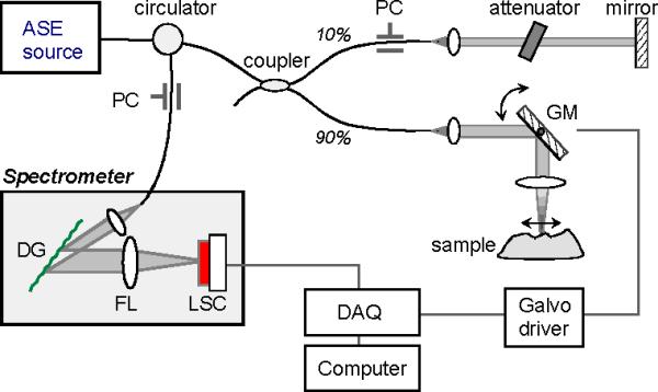
Figure 1 shows a schematic of the SD-OCT system. Amplified spontaneous emission from a semiconductor optical amplifier provided a broadband un-polarized Gaussian-like spectrum with full-width-half-maximum (FWHM) of 66 nm centered at 1315 nm. The total output power was 18.7 mW. A single-mode fiber interferometer consisting of a low-loss circulator and wavelength-flattened fiber-optic coupler with a 10/90 splitting ratio, was used for efficient sample arm illumination. At the distal end of the sample arm, a galvanometer-mounted mirror was driven with a saw-tooth waveform to provide transverse beam scanning over 5 mm at the sample. The numerical aperture of the probe was 0.054, resulting in confocal parameter of 1.1 mm and 1/e2 transverse resolution of 30 μm. The light returned from the two arms was directed to a spectrometer via a circulator. In the spectrometer, the optical spectrum was dispersed by a blazed diffraction grating (1200 lines per mm) and imaged by an achromatic doublet lens (focal length: 150 mm) onto an InGaAs CCD array line scan camera (Sensors Unlimited Inc., SU512LX). The total photon-to-electron conversion efficiency of the spectrometer was measured to be 0.8 and 0.3 for s- and p-plane polarization states, respectively. The conversion efficiency includes the diffraction efficiency of the grating and quantum efficiency (~85%) of the InGaAs CCD. The CCD had 512 detector pixels with a 50 μm pitch. The CCD detected a 106-nm bandwidth centered at 1315 nm, where each pixel was separated by 0.208 nm. This sampling interval resulted in a depth range of 2.08 mm. From the measured beam diameter at the diffraction grating, the spectral resolution was calculated to be 0.063 nm, which was narrower than that given by the pixel spacing of the array. The CCD camera was operated at its maximum readout rate of 18.94 kHz. The output of the camera was digitized by using a four channel data acquisition board (DAQ) with 12 bit resolution at a sampling rate of 5 MS/s per channel. The sampled data was transferred continuously to computer memory. A discrete Fourier transform (DFT) was performed on each set of 512 data points acquired by the CCD to produce an axial depth profile of the sample (A-line).
Fig. 1.

Schematic of the experimental setup. PC, polarization controller; GM, galvanometer-mounted mirror; DG, diffraction grating; FL, focusing lens; LSC, InGaAs line scan camera; DAQ, data acquisition board.
2.2 SD-OCT SNR Analysis
Fundamental noise sources in heterodyne detection include the electrical noise of the photodetector, shot noise, and relative intensity noise (RIN) from the reference arm light [17]. Maximum SNR is achieved when the RIN from the reference arm power is equal to the electrical noise. Shot noise limited detection is achieved if the shot noise dominates the electrical noise and RIN at this reference arm power. The amount of noise generated per CCD pixel can be conveniently expressed in terms of the number of noise-equivalent electrons accumulated in each CCD scan (A-line). With a CCD gain of 400 nV/electron, the total electrical noise, including the read out and dark noise of the camera and the quantization noise in the analog-to-digital conversion, was found to be Nel = 1617. RIN noise is given by NRIN = (f / Δν)1/2 Nref where Nref is the number of electrons per pixel generated by the reference arm light, f is the detection bandwidth or reciprocal of twice the exposure time of the CCD, and Δν=36.4 GHz denotes the FWHM spectral bandwidth of the reference light received by a single pixel (given a square-like spectrum). At its maximum scan rate of 18.94 kHz, our camera operated at an exposure time of 24.4 μs due to its finite readout time (46% duty cycle). This lead to f = 20.5 kHz. For the spectrometer efficiency of 0.55 (averaged over two polarization states), a maximum SNR in a single pixel was reached at Nref = 2.15 × 10⁶ where NRIN = Nel. This corresponded to 43% of the full well depth (5 × 10⁶ electrons) and a reference arm optical power of 24.6 nW. The number of shot noise electrons is given by Nsh = (Nref)1/2. At Nref = 2.15 × 10⁶, Nsh = 1466; therefore, the total noise power of our system was 3.4 times larger than the shot-noise limit.
It can be shown [5-8] that the sensitivity S, defined by the reciprocal of the noise equivalent reflectivity in the sample, is given by
| (1) |
where Σ Ns denotes the sum of electrons over the entire array generated by sample arm light returning from a 100% reflector, and α = 1 for an un-polarized (α = 2 for polarized) light source. We note that this expression is a valid approximation for uniform spectral density. In general, the actual signal and noise power for individual CCD pixels should be integrated over the spectral profile to obtain the overall SNR. We measured a total sample arm power of 6.3 mW returning from a gold mirror to the detector arm of the interferometer. This optical power corresponded to Σ Ns = 5.56 × 10¹¹. Therefore, for the noise power described earlier, Eq. (1) predicted a sensitivity of 112.1 dB. A more detailed calculation considering the actual Gaussian-like spectrum of the source and polarization-dependent spectrometer efficiency predicted a maximum theoretical sensitivity of 110.3 dB.
3. Experiment
3.1 Sensitivity
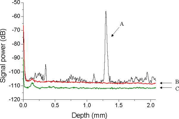
In our experiment, we set the total reference power to be between 7 and 11 μW (6.2 × 10⁸ - 9.7 × 10⁸ electrons) so that both the SNR and dynamic range were optimized. Figure 2 shows a typical point spread function (PSF), plotted in a log power scale, measured with a neutral density filter (total attenuation: -55 dB) and a gold mirror in the sample arm (Curve A, black line). The curve was obtained by averaging over 500 PSF's in power to reduce the fluctuation of the noise floor and present the fine structure in the signal more clearly. The reference arm mirror was positioned to produce a path length difference of 1.3 mm. To correct for the nonlinear k-space sampling interval, 512 sampled points per A-line scan were mapped to uniform frequency spacing by linear interpolation. Interpolation was performed by computing a DFT of the sampled data, zero padding, inverse DFT, and re-sampling of the resultant data at regular intervals [18]. This zero-padding process was essential to obtain a sidelobe-free PSF. The small noise peaks at other depth locations may be attributed to multiplicative noise due to fine structure in the source spectrum. Curve B (red line) represents the noise floor, averaged over 500 A-lines, obtained with the sample arm blocked. From the SNR of 51.7 dB, the ratio of the peak value of the signal power (curve A) and the noise floor (curve B), a sensitivity of 106.7 dB was obtained. Curve C (green line) shows the electrical noise level obtained with both the reference and sample arms blocked. The electrical noise was approximately 4.5 dB lower than the total noise level, in agreement with the noise analysis described above.
Fig. 2.

Typical point spread function obtained with a partial reflector with -55 dB reflectivity (curve A, black); noise floor measured with the reference light only (curve B, red); camera read out noise (curve C, green). All the curves were obtained by averaging over 500 consecutive measurements to facilitate comparison.
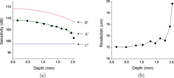
Figure 3(a) shows the sensitivity of the system measured as a function of depth (solid circles, black). The sensitivity is >109 dB from 0 to 0.5 mm and >105 dB up to 1.8 mm. The sensitivity decreases with depth because the finite resolution of the spectrometer reduces fringe visibility more strongly at higher fringe frequencies [12,18]. The magnitude of the decrease, R(z), can be shown to be:
| (2) |
where ζ = (π/2)·(z/zRD) denotes the depth normalized to the maximum ranging depth, zRD = λ2 / (4Δλ) [12] where Δλ is the wavelength spacing between pixels, and w = δλ / Δλ where δλ is the spectrometer's spectral resolution (FWHM). The Sinc and Gaussian functions in Eq. (2) are related via the Fourier transform to the square shape of CCD pixels [5] and Gaussian beam profile in the spectrometer, respectively. Fitting Eq. (2) to the sensitivity data (shown as Curve A'), yielded an y-offset of 109.25 dB and a spectrometer resolution of 0.104 nm (w = 0.5). The y-offset of 109.25 dB represents the sensitivity at zero depth and agrees well with the theoretically expected value of 110.3 dB based on Eq. (1). The fit value of 0.104 nm was larger than the predicted value by diffraction theory (0.063 nm). We attribute the discrepancy to aberrations caused by the lens. The additional 2.5 dB drop in sensitivity near the maximum depth of 2.08 mm may be attributed to imperfect mapping at high fringe frequencies. Equation (2) implies that the spectrometer resolution may limit the usable depth range unless it is substantially smaller than the sampling interval; for w = 1.0, Eq. (2) predicts a drop of 11.65 dB at the maximum depth (3.92 dB by the pixel size and 7.73 dB by the finite resolution). Curve B' (red) denotes the theoretical sensitivity of a shot-noise-limited SD-OCT system. Our system sensitivity had a 5-dB penalty due to the RIN and electrical noise and may be improved by use of dual balanced detection. It is notable, however, that our SD-OCT system is up to 10-dB more sensitive than the theoretical limit of TD-OCT using the same light source and imaging speed (Curve C', blue).
Fig. 3.

(a) Sensitivity measured as a function of depth (circles, black dotted line); theoretical fit (curve A', green); theoretical sensitivity for shot-noise-limited SD-OCT (curve B', red) and TD-OCT (curve C', blue). (b) Axial resolution measured as the FWHM
3.2 Resolution
Figure 3(b) shows the FWHM axial resolution determined from a Gaussian fit to the PSF in amplitude (reflectance profile) at various depths. At small depths below 0.5 mm, the free-space axial resolution was measured to be approximately 12 μm, which is close to the 11.6 μm calculated from the source bandwidth. However, the resolution decreased with the depth; it was 13.5 μm at a depth of 1.7 mm, and beyond 1.7 mm, a significant degradation of resolution was measured. These results indicate that the interpolation process is quite sensitive to small errors at high fringe frequencies, leading to poorer than transform-limited resolution at the maximum depth. These errors may be minimized by utilizing a linear array with more pixels. Future developments in InGaAs CCD array technology are merited to improve the ranging depth of high-speed 1.3 μm SD-OCT. Alternatively the ranging depth may be increased by a factor of two by measuring the complex spectral density from quadrature signals [13].
3.3 Images
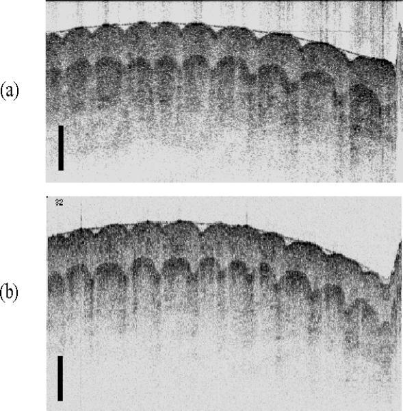
Figure 4(a) depicts the ventral portion of a volunteer's finger acquired by SD-OCT at 38 frames per second (fps). The image comprised 256 axial and 500 transverse pixels and was plotted using a logarithmic inverse grayscale lookup table. The focal point of the imaging lens was positioned in the middle of the depth range. For comparison, we also show an image of the same sample obtained with a state-of-the-art TD-OCT system from our laboratory (Fig. 4b) [2], which uses the same light source and interferometer configuration. The TD-OCT system obtains images at 4 fps, has a ranging depth of 2.5 mm, and a shot-noise-limited detection sensitivity of approximately 108 dB. Despite the nearly 10-fold higher imaging speed, the SD-OCT image exhibits similar resolution, contrast, and imaging penetration to the TD-OCT image.
Fig. 4.

(a) Image of a human finger acquired in vivo with the SD-OCT system at 38 fps (256 axial × 500 transverse pixels, 2.1 × 5.0 mm). (b) Image of the same human finger (250 axial × 500 transverse pixels, 2.5 × 5.0 mm) acquired at 4 fps using a state-of-the-art TD-OCT system. The scale bars represent 0.5 mm.
4. Conclusion
OCT imaging at center wavelengths around 1.3 μm has become the standard for non-ophthalmic applications because of increased optical penetration within tissues at 1.3 μm. For many important diagnostic indications, acceptance of OCT depends on its ability to screen large areas for disease. The current speed of clinical TD-OCT systems is not sufficient for these high-volume applications and is limited by source availability and SNR considerations. The SNR gain provided by SD-OCT allows us to use the same light sources of previous TD-OCT systems, while imaging at much higher speeds. In this paper, we have demonstrated a 1.3 μm SD-OCT system that obtains diagnostic quality images (sensitivity > 105 dB) at a rate of 38 fps (19,000 A-lines per second). The frame rate of our 1.3 μm SD-OCT system is approximately 10 times higher than that of state of the art TD-OCT systems using the same source. This advance will allow us to change the manner in which OCT is utilized in the clinical setting, as we now have a tool to screen large areas for disease as opposed to the point sampling approach mandated by the relatively slow speed of earlier TD-OCT technology.
Acknowledgements
This research was supported in part by research grants from the National Institutes of Health (R01-RR019768), Department of Defense (F4 9620-01-1-0014), Center for Integration of Medicine and Innovative Technology (CIMIT), and a gift from Dr. and Mrs. J.S. Chen to the optical diagnostics program of the Wellman Center of Photomedicine.
Footnotes
OCIS codes: (110.4500) Optical coherence tomography; (170.4500) Optical coherence tomography; (170.3880) Medical and biological imaging
References and links
- 1.Swanson EA, Huang D, Hee MR, Fujimoto JG, Lin CP, Puliafito CA. High-speed optical coherence domain reflectometry. Opt. Lett. 1992;17:151–153. doi: 10.1364/ol.17.000151. [DOI] [PubMed] [Google Scholar]
- 2.Tearney GJ, Yabushita H, Houser SL, Aretz HT, Jang IK, Schlendorf K, Kauffman CR, Shishkov M, Halpern EF, Bouma BE. Quantification of macrophage content in atherosclerotic plaques by optical coherence tomography. Circulation. 2003;106:113–119. doi: 10.1161/01.cir.0000044384.41037.43. [DOI] [PubMed] [Google Scholar]
- 3.Andretzky P, Lindner MW, Hermann JM, Schultz A, Konzog M, Kiesewetter F, Hausler G. Optical coherence tomography by spectral radar: dynamic range estimation and in vivo measurements of skin. Proc. SPIE. 1998;3567:78–87. [Google Scholar]
- 4.Wojtkowski M, Leitgeb R, Kowalczyk A, Bajraszewski T, Fercher AF. In vivo human retinal imaging by Fourier domain optical coherence tomography. J. Biomed. Opt. 2002;7:457–463. doi: 10.1117/1.1482379. [DOI] [PubMed] [Google Scholar]
- 5.Leitgeb R, Hitzenberger CK, Fercher AF. Performance of Fourier domain vs. time domain optical coherence tomography. Opt. Express. 2003;11:889–894. doi: 10.1364/oe.11.000889. http://www.opticsexpress.org/abstract.cfm?URI=OPEX-11-8-889. [DOI] [PubMed] [Google Scholar]
- 6.de Boer JF, Cense B, Park BH, Pierce MC, Tearney GJ, Bouma BE. Improved signal-to-noise ratio in spectral-domain compared with time-domain optical coherence tomography. Opt. Lett. 2003;28:2067–2069. doi: 10.1364/ol.28.002067. [DOI] [PubMed] [Google Scholar]
- 7.Choma MA, Sarunic MV, Uang C, Izatt JA. Sensitivity advantage of swept source and Fourier domain optical coherence tomography. Opt. Express. 2003;11:2183–2189. doi: 10.1364/oe.11.002183. http://www.opticsexpress.org/abstract.cfm?URI=OPEX-11-18-2183. [DOI] [PubMed] [Google Scholar]
- 8.Yun SH, Tearney GJ, de Boer JF, Iftimia N, Bouma BE. High-speed optical frequency-domain imaging. Opt. Express. 2003;11:2953–2963. doi: 10.1364/oe.11.002953. http://www.opticsexpress.org/abstract.cfm?URI=OPEX-11-18-2183. [DOI] [PMC free article] [PubMed] [Google Scholar]
- 9.Chinn SR, Swanson E, Fujimoto JG. Optical coherence tomography using a frequency-tunable optical source. Opt. Lett. 1997;22:340–342. doi: 10.1364/ol.22.000340. [DOI] [PubMed] [Google Scholar]
- 10.Golubovic B, Bouma BE, Tearney GJ, Fujimoto JG. Optical frequency-domain reflectometry using rapid wavelength tuning of a Cr4+:forsterite laser. Opt. Lett. 1997;22:1704–1706. doi: 10.1364/ol.22.001704. [DOI] [PubMed] [Google Scholar]
- 11.Fercher AF, Hitzenberger CK, Kamp G, El-Zaiat SY. Measurements of intraocular distances by backscattering spectral interferometry. Opt. Comm. 1995;117:43–48. [Google Scholar]
- 12.Hausler G, Lindner MW. Coherence radar and spectral radar - new tools for dermatological diagnosis. J. Biomed. Opt. 1998;3:21–31. doi: 10.1117/1.429899. [DOI] [PubMed] [Google Scholar]
- 13.Wojtkowski M, Kowalczyk A, Leitgeb R, Fercher AF. Full range complex spectral optical coherence tomography technique in eye imaging. Opt. Lett. 2002;27:1415–1417. doi: 10.1364/ol.27.001415. [DOI] [PubMed] [Google Scholar]
- 14.Wojtkowski M, Bajraszewski T, Targowski P, Kowalczyk A. Real time in vivo imaging by high-speed spectral optical coherence tomography. Opt. Lett. 2003;28:1745–1747. doi: 10.1364/ol.28.001745. [DOI] [PubMed] [Google Scholar]
- 15.Nassif N, Cense B, Park BH, Yun SH, Chen TC, Bouma BE, Tearney GJ, de Boer JF. In-vivo human retinal imaging by ultra high-speed spectral domain optical coherence tomography. Opt. Lett. doi: 10.1364/ol.29.000480. (in press) [DOI] [PubMed] [Google Scholar]
- 16.Bouma BE, Tearney GJ. Clinical imaging with optical coherence tomography. Acad. Radiol. 2002;9:942–953. doi: 10.1016/s1076-6332(03)80465-8. [DOI] [PubMed] [Google Scholar]
- 17.Sorin WV, Baney DM. A simple intensity noise reduction technique for optical low-coherence reflectometry. IEEE Photon. Technol. Lett. 1994;4:1404–1406. [Google Scholar]
- 18.Dorrer C, Belabas N, Likforman J-P, Joffre M. Spectral resolution and sampling issues in Fouriertransform spectral interferometry. J. Opt. Soc. Am. B. 2000;17:1795–1802. [Google Scholar]


