Abstract
We have designed and fabricated a microfluidic reactor array device for massively parallel in-situ synthesis of oligonucleotides (oDNA). The device is made of glass anodically bonded to silicon consisting of three level features: microreactors, microchannels and through inlet/outlet holes. Main challenges in the design of this device include preventing diffusion of photogenerated reagents upon activation and achieving uniform reagent flow through thousands of parallel reactors. The device embodies a simple and effective dynamic isolation mechanism which prevents the intermixing of active reagents between discrete microreactors. Depending on the design parameters, it is possible to achieve uniform flow and synthesis reaction in all of the reactors by proper design of the microreactors and the microchannels. We demonstrated the use of this device on a solution-based, light-directed parallel in-situ oDNA synthesis. We were able to synthesize long oDNA, up to 120 mers at stepwise yield of 98 %. The quality of our microfluidic oDNA microarray including sensitivity, signal noise, specificity, spot variation and accuracy was characterized. Our microfluidic reactor array devices show a great potential for genomics and proteomics researches.
Keywords: Oligonucleotide microarray, Microfluidics, In-situ synthesis, Photogenerated acid, Hybridization, Genomics
1. Introduction
The completion of the draft version of sequences of the human genome and other organisms signals the beginning of a new era for the scientific community to not only identify genes, but also understand their function and expression. DNA microarrays are powerful tools for this purpose by providing a systematic way in the analysis. There are two types of nucleic acid microarrays: complementary DNA (cDNA) and oligonucleotide DNA (oDNA) microarray [1]. For most applications, the oDNA microarray is more attractive because it offers superior hybridization specificity, freedom in sequence design and the choice of tailored chain [2].
There are two major techniques of making oDNA microarrays: attachment of presynthesized oligomers by spotting and parallel in-situ synthesis [2]. Making oDNA microarray by spotting technique can be done using various commercial spotting machines [3]. Therefore, it is widely used in molecular biology labs. However, the technology suffers from problems of spot uniformity and requires large numbers of presynthesized oligomers. Parallel in-situ synthesis, in which a plurality of oDNA probes are directly synthesized base by base on a substrate surface, eliminates the problems associated with the spotting technology and does not require the maintenance of large oligomer libraries.
In order to achieve the parallel in-situ synthesis, the reaction involved in oDNA synthesis is controlled spatially in a stepwise fashion. Several approaches have been proposed and/or implemented to achieve this goal [4-11]. The most well known oDNA microarray is the GeneChip® array from Affymetrix. This microarray is in-situ synthesized using light gated by photomasks to cleave off the protecting photolabile groups in a spatially controlled manner [4]. Although this synthesis strategy is suitable for making high density microarray, it has several limitations. First, it uses expensive photolabile reagents and low stepwise yield synthesis chemistry. This low stepwise yield limits the size and quantity of oligonucleotide probes on the array. Secondly, each step of the synthesis cycles requires the use of a different photomask to control light spatially. As a result, the approach is not suitable for making custom oDNA microarrays. Singh-Gasson [5] has demonstrated the value of using a digital microarray projector to create virtual masks to circumvent the need for expensive photomasks. NimblGen [6] and Febit [7] have subsequently employed this synthesis approach to make oDNA microarrays commercially. Even though this approach greatly reduces the manufacturing cost and turnaround time for making a custom oDNA microarray, similar to the Affymetrix approach, it uses expensive photolabile phosphoramidite reagents with low stepwise yield chemistry. In order to make a custom oDNA microarray with standard phosphoramidite coupling chemistry, our research group proposed a new method to make oDNA microarray, based on three key innovations: Photogenerated acid (PGA) chemistry, digital maskless photolithography and microreactor array devices [12-16]. In this paper, we describe a design and a fabrication of a microfluidic reactor array device that allows us to perform massively parallel in-situ oDNA synthesis by PGA chemistry with ultra low chemical consumption, and a high purity level. We also present the results that demonstrate the quality and performance of microfluidic oDNA microarrays.
2. Materials and methods
2.1. Microarray synthesizer
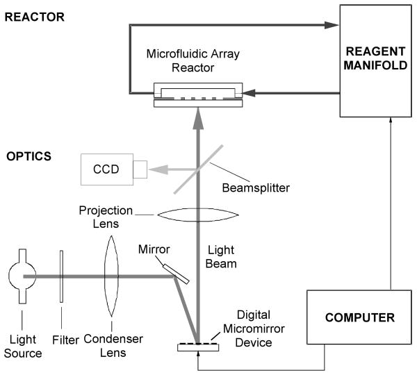
The microarray synthesizer consists of projection optics, a reactor assembly, a reagent manifold, and a computer control system shown in Fig 1. A mercury arc lamp was used as the light source. A digital micromirror device (DMD, Texas Instruments) was used to generate light patterns projected through a projection lens onto the surface of microfluidic reactor array chip housed in a flow-through cartridge. A beam splitter and a CCD video camera (SONY) were used to assist projector-microarray plate alignment. The cartridge made from 316-stainless steel was connected to a commercial DNA/RNA synthesizer (Expedite 8909, PerSeptive) which served as a reagent manifold. Computer software, written in C++, was developed in-house to generate light patterns based on predetermined oDNA chip layout.
Fig. 1.
Schematic illustration of a programmable microarray synthesizer.
2.2. Fabrication of microfluidic reactor array devices
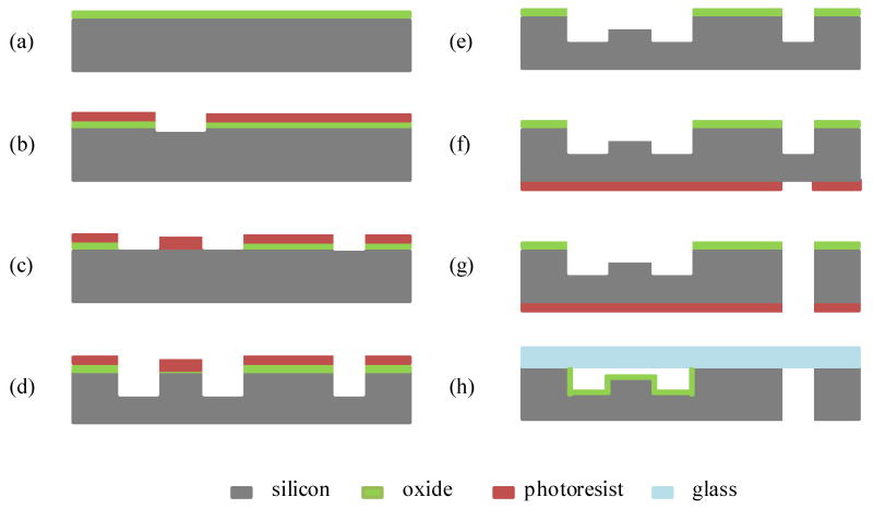
The microfluidic reactor array device was fabricated at the Solid State Electronics Laboratory at the University of Michigan. The device was made of silicon substrate anodically bonded to a Corning 7740 glass wafer. The silicon substrate contains three levels of deep etched fluidic features: microreactors (10-40 μm), microchannels (100-160 μm), and through inlet/outlet holes (550 μm). The fabrication procedure begins with a 4″ (100) Si wafer with thermal oxide thickness of 0.6 um (Fig. 2a). A layer of photoresist (PR 1813, Hoechst Celanese) was spin-coated. The microreactor pattern was transferred to the layers of photoresist and thermal oxide by photolithography and wet buffered HF etching (Fig. 2b). The photoresist was then removed by a resist stripper (PRS 2000, JT Baker Inc.). A new layer of resist (PR 1827, Hoechst Celanese) was applied by spin coating. The microchannel pattern was transferred to the layers of photoresist and thermal oxide by photolithography and reactive ion oxide etching (Fig. 2c). The microchannel pattern was further transferred to the silicon wafer using a deep silicon etcher developed by the Surface Technology Systems (STS) to obtain 90-120 μm deep microchannels (Fig. 2d). The photoresist was removed by the resist stripper to reveal the underlying layer of microreactor patterned oxide used as an etch mask. The wafer was re-etched in the deep silicon etcher to obtain 10-40 μm deep microreactors and 100-160 μm deep microchannels (Fig. 2e). After the microreactor and microchannel features were formed on the front side of the wafer, the new layer of photoresist (AZ 9260, Clariant) was applied to the backside of the wafer. The through inlet/outlet hole pattern was transferred to the photoresist layer by photolithography (Fig. 2f). The wafer was then loaded into the deep silicon etcher to create the through inlet/outlet holes (Fig. 2g). The layers of photoresist and thermal oxide were then removed. The wafer was cleaned using RCA. A 0.2 μm thick thermal oxide layer was grown on the surface to allow subsequent functionalization of the surface for chemical reactions. Finally, the microfabricated silicon wafer was anodically bonded with a glass wafer at 400 °C and 1000 V (Fig. 2h).
Fig. 2.
Simplified process flow for the microfluidic reactor array device (a) growing a thermal oxide layer; (b) defining the microreactor pattern to PR and thermal oxide layers; (c) defining the microchannel pattern to PR and thermal oxide layers; (d) etching a silicon wafer to create microchannels; (e) etching a silicon wafer to create microreactors; (f) defining the through inlet/outlet hole pattern to the backside of the wafer; (g) etching a silicon wafer to create the through-holes and (h) growing a thermal oxide and bonding to a glass wafer.
2.3. Oligonucleotide synthesis
Procedures of oligonucleotide synthesis were previously described [16]. Briefly, the process consisted of first placing the microfluidic reactor array chip in a derivatization holder, washing the chip in 95 % ethanol, and derivatizing it in a 1 % solution of N-(3-triethoxy-silylpropyl)-4-hydrooxybutyramide in ethanol. After derivatization, the chip was washed with 95 % ethanol and then cured under nitrogen gas at 60 °C. The chip was removed from the derivatization holder and was installed in a synthesis holder. This holder was connected to an Expedite 8909 DNA synthesizer. The synthesizer was programmed to deliver reagents including a photogenerated acid precursor (PGA-P) to the chip for DNA synthesis. All of the synthesis steps, except a deprotection step for each cycle, were the same as those performed in conventional oligonucleotide synthesis. In the deprotection step, the array plate was illuminated with a computer generated pattern. The cycles were repeated to achieve the desired sequence and length. For a stepwise yield experiment, all sequences were coupled with 1:10 fluorescein:T phosphoramidites. After extensive washing with ethanol, the fluorescein moiety was activated by reacting the chip with 1:1 ethylenediamine: ethanol. The chip was washed with ethanol and water and then filled with a hybridization buffer.
2.4. Microarray hybridization and washing
The Cy3 and Cy5 labeled oligonucleotide samples were purchased from Inegrated DNA Technologies (IDT). Prior to hybridization, the labeled samples were pooled. BSA (1 mg/ml), formamide, and 20× SSPE were added to make the final concentration of 6× SSPE and 25% formamide in 100 μl. Hybridizations were performed for 18 hours at 24-42 °C by recirculating the samples through the microarrays. After hybridization, the microarrays were washed by circulating 500 μl of 6× SSPE containing 25% formamide, 500 μl of 6× SSPE and 500 μl of 1× SSPE, sequentially. To stabilize the helices, 250 μl of 6× SSPE was pumped through the chip for imaging. The microarrays were imaged on an Axon 4000B scanner.
3. Results and disscusion
3.1. Parallel in-situ oDNA synthesis using photogenerated acids
We have developed a novel method to synthesize oligonucleotides by modifying the deprotection step. In the deprotection step, we replace a standard acid such as tricholoacetic acid (TCA) with the photogenerated acid precursors (PGA-Ps) while keeping the rest of the synthesis steps unchanged [12]. The PGA-P produces the photogenerated acid (PGA) upon light exposure. Our strategy for the massively parallel in-situ synthesis of oDNA on a surface is based on controlling acid generation upon light exposure, to deprotect the protecting acid-labile groups in a spatial manner. The light can be gated spatially using a programmable maskless system, shown in Figure 1. Figure 3 shows a schematic illustration of steps for the solution-based, light-directed parallel in-situ oDNA synthesis. In the first step, linker molecules are attached to a surface. Each linker molecule contains a reactive functional group that is protected by an acid-labile group. Next, a PGA-P is applied to the surface. A predetermined light pattern is the projected onto the surface. At illuminated sites, acid is produced. The acid causes the cleavage of the protecting acid-labile groups from the linker molecules and lead to the formation of terminal OH groups. At dark sites, no acid is produced and, therefore, the protecting acid labile groups remain intact. The surface is then washed and subsequently flooded with the monomer. Monomer molecules with a terminal protecting acid-labile group form chemical bonds with the terminal OH groups on the surface. This chain propagation process is repeated until the desired length and sequences of oDNA are formed at all selected surface sites. As a result, the approach makes it possible for us to perform a solution-based, light-directed parallel in-situ oDNA synthesis without using special monomers containing a protecting photolabile groups. In addition, the programmable maskless system has provided us with flexibility for making microarrays of any arbitrary oDNA sequences without additional cost and time.
Fig. 3.
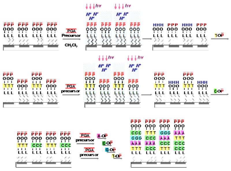
Schematic illustration of (a) parallel in-situ oDNA synthesis using PGA chemistry. L - linker group; Pa - acid labile protecting group; H+ - proton; T, A, C, G-DMT – phosphoramidite monomers; hυ–light
3.2. Microfluidic reactor array for a solution-based light directed oDNA synthesis
Microfluidic technology has had a revolutionary impact on both fundamental research and advanced chemical, biological, and diagnostic analyses because of its advantages for processing with less reagents, combining multiple processing steps into a single system, and minimizing sample processing and handling. Due to these unique characteristics, microfluidic technology has demonstrated great potential for integration with microarray technology [17]. For example, Baum et al. have developed a technology combining a microfluidic device with an integrated optical benchtop instrument for in-situ light-activated oDNA synthesis with photolabile chemistry, hybridization and detection [7]. The device consists of a silicon layer with serpentine layout enclosed in a glass cover sandwich. Even though this device significantly reduces the overall chemical consumption during synthesis compared with conventional solid phase oDNA synthesis, it is not suited for a solution-based light directed oDNA synthesis where some chemical reaction steps occur in the liquid phase. The microfluidic architecture of this device serves as a guide for liquid flow but does not provide an effective way for chemical isolation to prevent the mixing of active reagents among adjacent reaction sites (“cross talk” effect). Any “cross talk” effect would significant degrade the fidelity of the sequence synthesized. As a result, we have developed a new type of the microfluidic reactor array device containing physically separated reaction cells that eliminate the potential for “cross talk” effect. The structure, operation, fabrication and design of this microfluidic array device are described below.
3.3. Microfluidic reactor array structure and operation
One of the key issues for a solution-based light-directed parallel in-situ oDNA synthesis is to confine the PGA-produced acid inside each microreactor for a sufficient amount of time to complete the deprotection reaction and avoid diffusion of the acid into neighboring unexposed microreactor. We have developed a passive highly miniaturized microfluidic reactor array device to achieve this isolation. The passive microfluidic reactor array device is made of silicon anodically bonded to glass. The silicon side of our device contains the microfluidic networks of microchannels and microreactors as shown in Fig. 4a. There are three levels of deep etched features in this microfluidic reactor array device. In contrast to Baum's microfluidic device in which the glass-silicon-glass sandwich structure is specially designed for oDNA synthesis and hybridization detection using a Geniom optical instrument, our microfluidic reactor array device can be used with a microarray synthesizer setup as described in section 2.1 and can be scanned on any commercial scanners for hybridization detection.
Fig. 4.
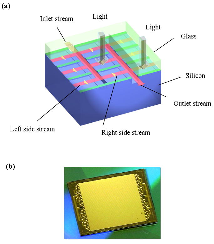
(a) Structure and operation of a microfluidic reactor array device; and (b) photograph of a microfluidic reactor array device.
As shown in Fig. 4a, the operation principle of the device is as follows. During operation, a fluid stream flows into the device through inlet microchannels and splits into left-side and right-side streams that enter microreactors along the inlet microchannels. Adjacent microreactors are separated from each other by the isolation walls between them. The top surface of the isolation walls is anodically bonded with glass, through which light can pass to facilitate photolytic reaction and fluorescence detection. Therefore, the side streams in the adjacent microreactors do not mix with each other through the isolation walls. After passing through the microreactors, the side streams merge into the outlet microchannels and flow out of the device into the drain. During the deprotection reaction, a fluid containing a PGA-P is sent into the device and a light beam is directed at the microreactors to generate the PGA while no PGA is present inside the un-illuminated microreactors. After a short period of time, sufficient for the deprotection reaction, flow resumes with the fluid flowing through microreactors at a sufficiently high flow rate so that there is no back-diffusion of the PGA into inlet microchannels. With this structural and operation design, each individual microreactor is dynamically isolated and multiple of discrete chemical reactions can occur in parallel among any arbitrarily selected group of microreactors without on-chip active components such as a pump and/or valve. This simplicity makes the device low cost for manufacturing and robust for operation.
3.4. Microfluidic reactor array fabrication
Silicon can be etched by either a wet etching or dry etching method. However, wet etching with a KOH solution exhibits highly orientation-dependent etch characteristics [18]. Because of the limitation of orientation dependent etching itself, it becomes difficult to decide which mask design will provide the desirable etched structure. To date, there is no adequate tool for designing the etch masks for complicated etched structures [19]. In this study, we used a deep reactive ion etching system that was developed by Surface Technology Systems (STS) to overcome these problems. The system is based on a sequence of alternating etch and passivation cycles [20]. The etchant gas is SF6 and the passivation gas is C4F8. During each passivation step, the gas is dissociated from the plasma to form ion and radical species. A fluorocarbon polymer ((CxFy)n) is deposited over the entire surface of the wafer. During each etch step, the etchant gas is dissociated into ions and free radicals. Ions, created in the bulk plasma, are accelerated to the substrate surface. Ion bombardment helps to remove the surface polymer. The increase of ion energy, by adjusting platen bias, removes the fluorocarbon polymer from horizontal surfaces at a faster rate than from vertical surfaces. After the polymer is removed, the silicon at the base of the trench is etched isotropically by fluoride radicals to form a volatile SiFx during the rest of the etch cycle, while the vertical surface remains protected by the fluorocarbon polymer layer. As a result, anisotropic etching without dependency on crystal orientation can be achieved by this process.
As mentioned, our microfluidic array device consists of three levels of deep etched features: microreactors, microchannels, and through inlet/outlet holes. Each level could be transferred by spin-coating photoresist, photolithography and etching. To achieve three levels of depth, these cycles are repeated three times. However, after each etched structure is formed, it becomes increasingly difficult to apply each subsequent layer of photoresist so that it is thick enough to protect the covered structures during the subsequent etch. To eliminate spin coating on the deep structures, we used both a double-masking technique and a backside alignment technique in our fabrication step. The double-masking technique is the technique in which the patterned top mask is formed on an already patterned underlying mask. After the pattern of the top mask is transferred to the substrate by etching, the top mask is removed to reveal the underlying mask. Then, the pattern of the underlying mask is transferred to the substrate. For example, to obtain 20 μm deep microreactors and 120 μm deep microchannels, we chose a photoresist for the top mask and a thermal oxide (0.6 μm) for the underlying mask because of its high etching selectivity (more than 200) between silicon and silicon dioxide, thick enough to subsequently use as a deep etch mask on silicon wafer. We transferred the microreactor pattern to a layer of thermal oxide on the wafer (Fig. 2b) and then covered this pattern with photoresist, followed by transferring a microchannel pattern into the photoresist and thermal oxide (Fig. 2c). Subsequently, 100 μm deep microchannels were etched into the wafer (Fig. 2d). After the photoresist was removed to reveal the patterned microreactor oxide layer, the wafer was re-etched for an additional 20 microns to obtain the 20 μm deep microreactors and 120 μm deep microchannels (Fig. 2e).
Prior to bonding a microfabricated silicon wafer to a glass wafer, we grow a 0.2 micron thick silicon dioxide layer over the entire silicon surface. As a result, oDNA can be in-situ synthesized on both the lower surface of the glass substrate and the oxidized upper surface of the silicon substrate. This three dimensional configuration enhances the hybridization signals two-fold compared with one sided or planar surface oDNA chips. Other advantages of the microfluidic array have been observed. Since the device is sealed, the oDNA probes are effectively shielded from the surrounding environment. This reduces contamination or damage to the oDNA probes during and after the synthesis, and oxidation or degradation of dyes during the hybridization and/or laser scanning. For example, no Cy5 signal degradation was observed after multiple scans over the microfluidic chip while ozone-induced Cy5 degradation is a well known problem with glass slide microarray chips [21].
The microfluidic array reactor device, shown in Figure 4b, contains 3698 individual microreactors. The overall measurements of the device were 1.7×2.0 cm2 in size. The device is highly miniaturized with a total internal volume of only 10 μl and each individual microractor volume of 270 pl. Its miniaturization significantly reduces reagent consumption and cost. Another uniqueness of this microfluidic reactor array device is that the cross sectional dimensions of microreactors are very small (∼ less than 40 μm). Therefore, mass transfer between the surface and the liquid is significantly enhanced compared to larger gap reactors. As a result, the rate of chemical reactions and hybridization is significantly enhanced.
3.5. Design of microfluidic reactor array devices
Because there are surface reactions during the synthesis and hybridization in the individual microreactors, it is crucial to supply quantities of reagents uniformly to microreactors in the device. To achieve this goal, we developed the simple modeling used to facilitate the step in the design and optimization of our microfluidic reactor array devices.
For the steady state, incompressible fluid flow in pipe, the head loss (Δh) for length, L, of pipe can be evaluated as
| (1) |
where, Δh is the head loss, Q is the flow rate of the fluid, P is the wetted perimeter,
A is the cross section area of the pipe, μ is the viscosity of the fluid,
ρ is the density of the fluid, and k is the fluid flow resistance
This equation can be analogous to an ohm's law defined as
| (2) |
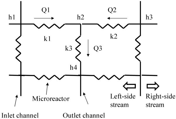
Therefore, we can use the electrical circuit network to represent the fluid flow in the device, as shown in Fig. 5. We can obtain one continuity equation at each node of the electrical equivalent network and a set of these equations representing the device. This set of equations can be solved simultaneously to obtain the head (h) at each node of the electrical network. We can then use these values to calculate the flow rate through the microchannels and microreactors and to obtain the flow patterns of the side streams through the microreactors along the flow.
Fig. 5.
Portion of the electrical equivalent network of the microfluidic array device.
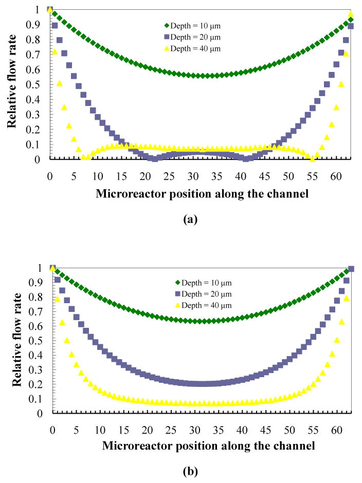
Although the actual microfluidic device contains thousands of microreactors, the studied model is scaled to hundreds of microreactors to reduce computation time and resources. Matlab's code was used to simulate the flow pattern of the microfluidic device with eight inlet/outlet microchannels (90 μm wide and 8000 μm long), each containing 64 microreactors (90 μm wide and 200 μm long). Fig. 6a and 6b shows the relative flow patterns of one of the left-side and right-side streams through microreactors along the flow at different microreactor depths ranging from 10 μm to 40 μm. In these simulations, the microchannel depth is kept constant at 100 μm. The result shows the relative flow rate going through each microreactor is not uniform. The flow is faster at the inlet and outlet ends of the device and slower in the middle. The left-side stream flow pattern is also different from the right-side stream flow pattern. The flow uniformity is degraded by increasing the depth of microreactor. As we increase the depth of microreactors from 10 μm to 20 μm, we observe a sudden disruption of the flow distribution in the microreactors, especially in the right-side streams. The flow rate becomes zero at two locations along the flow of the right-side streams through microreactors. In addition, the result indicates a change of flow direction from right to left. The similar degradation of flow uniformity can also be observed when the depth of microchannel decreases. From simulation results, to avoid this non-uniformity flow problem and change of flow direction, we need to modify the dimesions of the device in such a way that the pressure drop across the microreactors is increased relative to the microchannels. The validation of the model and testing of flow uniformity in the microfluidic reactor array device are described in detail in the next section.
Fig 6.
Relative flow pattern of (a) left-side streams and (b) relative flow pattern of right-side streams through microreactors along the flow at different microreactor depths ranging from 10 to 40 μm with a microchannel depth of 100 μm.
3.6. Microfluidic oDNA microarrays
To validate the modeling results described above, oDNA was synthesized in-situ on a microfluidic reactor array device where the microreactor depth has been intentionally increased. Fig.7 shows a fluorescent image of a device that contains fluorescein-tagged dimers arranged in a checkerboard pattern. In this device, the bright spots are supposed to have the same intensity everywhere. However, we can see two dark regions in every other column. All the dark regions are in the right-flow columns whereas the left-flow regions are uniform. We believe that this results from a sharp decline in the flow of the reagents to that region during synthesis. Using a CCD camera and alternating solvents (organic/water), we actually visualized a sluggish flow in these regions that eventually became dark. The liquid front stayed in the regions (inside the microreactors) for a couple of seconds. However, in the left-flow columns the liquid front passed through the microreactor very quickly. This evidence corroborates the simulation results shown in Fig. 6a and 6b. As discussed previously, the flow uniformity could be achieved by modifying the dimensions of the microarrays in such the way that the pressure drop across the microreactors is increased relative to the microchannels. The pressure drop across the microreactors can be increased by decreasing microreactor depth, or modifying microreactor shape. After dimension and shape modification, and fabrication of the device, we synthesized a set of 45 mer of 252 unique probe sequences repeated 15 times on the microfluidic reactor array. The microarray was then hybridized with complementary sequences labeled with Cy3 and Cy5 dyes. The hybridized microarray data shows high signal uniformity within the microreactors and between microreactors. The coefficients of variation (CV) values, defined as a standard deviation divided by a mean and represented the uniformity characteristics, within the microreactors are typically on an average of 5% for the Cy3 channel and of 7% for the Cy5 channel. Microreactor to microreactor CV values for replicate probes within the same microarray as a measure of reproducibility was also measured. The average value of CV for replicate probes in the Cy3 channel is 10% while that in the Cy5 channel is 12%. To measure the sensitivity and linear dynamic range of the microfluidic oDNA array, we synthesized unique probe sequences of PUX3 gene in 20 positions throughout the array. We then prepared seven different concentrations (ranging from 0.01 pM to 10,000 pM) of 45 mer complementary oligonucleotide target labeled with Cy3. The samples are hybridized to seven individual microarrays. Figure 8 shows the average signal intensities for different probe concentrations. The result demonstrates that signal was detected at values as low as 0.01 pM and the signal was linear to 1000 pM with a regression coefficient of 0.98. This data also illustrates a dynamic range of more than 4 logs.
Fig. 7.
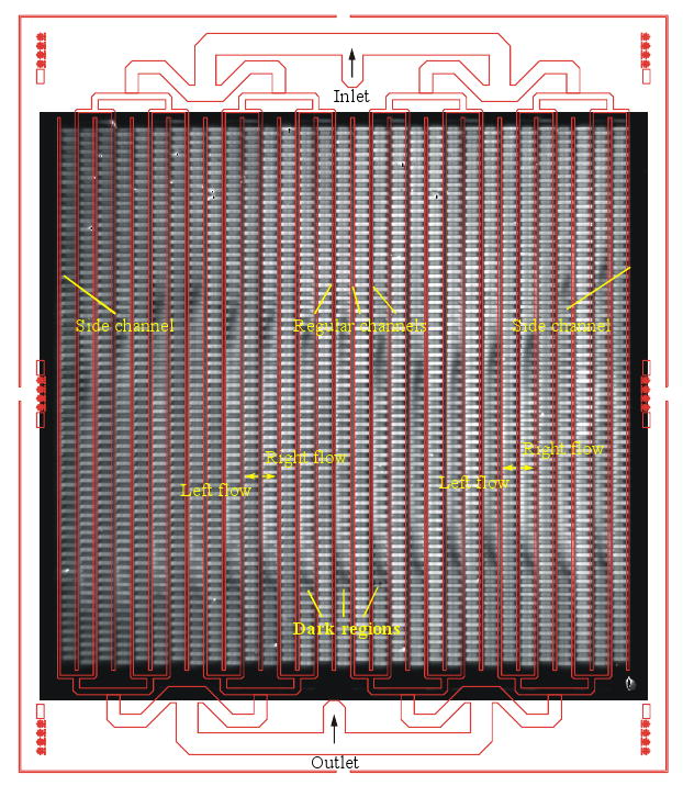
Fluorescent image of a chip containing fluorescein-tagged dimer in a checkerboard pattern.
Fig. 8.
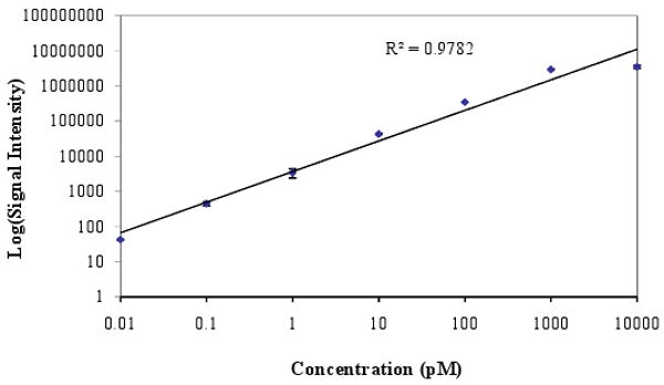
Plot between log average signal intensity and target concentration obtained from a hybridization of 45 mer complementary oligonucleotide target labeled with Cy3 to the microfluidic array device containing unique probe sequences of PUX3 gene in 20 positions throughout the device.
During a photolytic reaction in oDNA synthesis cycle as described above, success in liquid isolation is critical for obtaining high sequence fidelity and specificity. In this study, the sequence fidelity was validated by means of hybridization using labeled target sequences. If mismatches can be discriminated, fidelity can be effectively validated. We synthesized the oDNA probes representing both perfect match sequence and mismatch sequences with one, two and three base substitution of GAP2 gene on the microfluidic reactor array device. The microarray was then hybridized with perfect match complementary targets over a range of hybridization temperatures from 24 °C to 42 °C. We can clearly observe the discrimination between matched and mismatched probes. As shown in Fig. 9, the matched probes have at least ten times higher signal than the mismatched ones even at temperature as low as 24 °C. The result confirms the success of the high fidelity oDNA synthesis. In other words, liquid isolation during oDNA synthesis on our microfluidic reactor array device has been successfully accomplished.
Fig. 9.
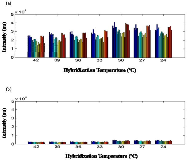
Plot of signal intensity of (a) perfect match probes and (b) mismatch probes hybridized with perfect match complementary target sequences of GAP2 gene from 14 individual experiments over a range of hybridization temperatures from 24 °C to 42 °C.
To monitor the synthesis stepwise yield of a solution-based, light-directed oDNA synthesis chemistry in our microfluidic reactor array device, fluorescence dye phosphoramidite was in situ coupled to different length oligonucleotides. Fig. 10 shows four different copies of the stepwise yield experiment going from 1 to 120 bases. As the number of bases increases, fluorescent intensity decreases due to incomplete 5′O-DMT deprotection of each synthesis cycle. As a result, less free OH groups are available for the next synthesis cycle. The relative amount of the free hydroxyl groups after 100 synthesis cycles is 13%, corresponding to a stepwise yield of 98% which is superior to one achieved by Affymetrix [22,23]. Therefore, we were able to perform solution-based, light-directed parallel in-situ oDNA synthesis upto 120 mers on the microfluidic reactor array device. Such long oligomers exhibit more specificity for detection of their target genes than conventional short oligomers, due to a reduced chance of cross hybridization with unrelated target sequences [24].
Fig. 10.

Fluorescent image from a section of a microfluidic oDNA microarray containing four different copies of the stepwise yield experiment going from a monomer to a 120 mer.
4. Conclusion
Development of synthesis methods using high yield acid-labile protection group containing monomers rather than photolabile protection group containing monomers is desirable to produce microarrays of superior quality, general adaptability and reduced cost. However, using photogenerated acid produced upon light exposure for deprotection reaction requires isolation of reaction sites from each other to prevent diffusion of reagents afterwards. We have successfully developed and fabricated a microfluidic reactor array device for a solution-based, light-directed parallel in-situ oDNA synthesis. The microfluidic reactor array device is a simple external pressure driven device and embodies an effective dynamic isolation mechanism which prevents the intermixing of active reagents between discrete microreactors. Therefore, it does not require any complicated built-in valves, pumps and electrodes, which would add complexity to the manufacturing processes or lower the robustness and reliability of the device operation. The additional advantage of the microfluidic reactor array device lies in its miniaturization and thus significantly reduced reagent consumption and enhanced both the in-situ synthesis reaction and the hybridization. We have demonstrated the use of the microfluidic reactor array device with solution-based, light-directed oDNA synthesis and examined the high quality and performance of the microfluidic oDNA microarray. The capability of the microfluidic reactor array device is not limited to oligonucleotides but extends peptides, carbohydrates and a variety of organic molecules. The availability of this device will not only accelerate the current genomic and proteomic based research but also spur new applications previously impossible due to time and cost barriers such as rapid synthesis of large DNA [16, 25] and oligonucleotide library [26].
Acknowledgments
This research is supported by grants from NSF, and Michigan Life Sciences to E.G., from Merck Genome Research Institute to X.G. and E.G., from NIH/NCI, the Welch Foundation, the National Institute of Health, the National Foundation of Cancer Research, and Texas Higher Education Coordinating Board ATP to X.G., and from NIH/HGRI to X.Z..
Footnotes
Publisher's Disclaimer: This is a PDF file of an unedited manuscript that has been accepted for publication. As a service to our customers we are providing this early version of the manuscript. The manuscript will undergo copyediting, typesetting, and review of the resulting proof before it is published in its final citable form. Please note that during the production process errors may be discovered which could affect the content, and all legal disclaimers that apply to the journal pertain.
References
- 1.Lemieux B, Aharoni A, Schena M. Overview of DNA chip technology. Mol Breeding. 1998;4:277–289. [Google Scholar]
- 2.Hoheisel JD. Oligomer-chip technology. Trends Biotechnol. 1997;15:465–469. [Google Scholar]
- 3.Drobyshev AL, Zasedatelev AS, Yershov GM, Mirzabekov AD. Massive parallel analysis of DNA-Hoschst 33258 binding specificity with a generic oligodeoxyribonucleotide microchip. Nucleic Acids Res. 1999;27:4100–4105. doi: 10.1093/nar/27.20.4100. [DOI] [PMC free article] [PubMed] [Google Scholar]
- 4.Fodor SPA, Read JL, Pirrung MC, Stryer L, Lu AT, Solas D. Light-directed, spatially addressable parallel chemical synthesis. Science. 1991;251:763–773. doi: 10.1126/science.1990438. [DOI] [PubMed] [Google Scholar]
- 5.Singh-Gasson S, Green RD, Yue Y, Nelson C, Blattner F, Sussman MR, Cerrina F. Maskless fabrication of light-directed oligonucleotide microarrays using a digital micromirror array. Nat Biotechnol. 1999;17:974–978. doi: 10.1038/13664. [DOI] [PubMed] [Google Scholar]
- 6.Nuwaysir EF, Huang W, Albert TJ, Singh J, Nuwaysir K, Pitas A, Richmond T, Gorski t, Berg JP, Ballin J, McCormick M, Norton J, Pollock T, Sumwalt T, Butcher L, Porter D, Molla M, Hall C, Blattner F, Sussman MR, Wallace RL, Cerrina F, Green RD. Gene expression analysis using oligonucleotide arrays produced by maskless photolithography. Genome Res. 2002;12:1749–1755. doi: 10.1101/gr.362402. [DOI] [PMC free article] [PubMed] [Google Scholar]
- 7.Baum M, Bielau S, Rittner N, Schmid K, Eggelbusch K, Dahms M, Schlauersbach A, Tahedl H, Eeier M, Guimil R, Scheffler M, Hermann C, Funk J, Wixmerten A, Rebscher H, Honig M, Andreae C, Buchner D, Moschel E, Glathe A, Jager E, Thom M, Greil A, Bestvater F, Obermeir F, Burgmaier J, Thome K, Weichert S, Hein S, Binnewies T, Foitzik V, Muller M, Stahler CG, Stahler PF. Validation of a novel, fully integrated and flexible microarray benchtop facility for gene expression profiling. Nucleic Acids Res. 2003;31:e151. doi: 10.1093/nar/gng151. [DOI] [PMC free article] [PubMed] [Google Scholar]
- 8.Lausted C, Dahl T, Warren C, King K, Smoth K, Johnson M, Saleem R, Aitchison J, Hood L, Lasky SR. POsaM: a fast, flexible, open source, inkjet oligonucleotide synthesizer and microarrayer. Genome Biol. 2004;5:R58. doi: 10.1186/gb-2004-5-8-r58. [DOI] [PMC free article] [PubMed] [Google Scholar]
- 9.Moorcroft MJ, Meuleman WRA, Latham SG, Nicholls TJ, Egeland RD, Southern EM. In situ oligonucleotide synthesis on poly(dimethylsiloxane): a flexible substrate for microarray fabrication. Nucleic Acids Res. 2005;33:e75. doi: 10.1093/nar/gni075. [DOI] [PMC free article] [PubMed] [Google Scholar]
- 10.Egeland RD, Southern EM. Electrochemically directed synthesis of oligonucleotides for DNA microarray fabrication. Nucleic Acids Res. 2005;33:e125. doi: 10.1093/nar/gni117. [DOI] [PMC free article] [PubMed] [Google Scholar]
- 11.Phillips MF, Lockett MR, Rodesch MJ, Shortreed MR, Cerrina F, Smith LM. In situ oligonucleotide synthesis on carbon materials: stable substrates for microarray fabrication. Nucleic Acids Res. 2008;36:e7. doi: 10.1093/nar/gkm1103. [DOI] [PMC free article] [PubMed] [Google Scholar]
- 12.Gao X, Yu P, LeProust E, Sonigo L, Pellois JP, Zhang H. Oligonucleotide synthesis using solution phootogenerated acids. J Am Chem Soc. 1998;120:12698–12699. [Google Scholar]
- 13.LeProust E, Pellois JP, Yu P, Zhang H, Gao X, Srivannavit O, Gulari E, Zhou X. Digital light-directed synthesis. A microarray platform that permits rapid reaction optimization on a combinatorial basis. J Comb Chem. 2000;2:349–354. doi: 10.1021/cc000009x. [DOI] [PubMed] [Google Scholar]
- 14.Srivannavit O, Gulari M, Gulari E, LeProust E, Pellois JP, Gao X, Zhou X. Design and fabrication of microwell array chips for a solution-based PGA-catalyzed parallel oligonucleotide DNA synthesis. Sens Actuators, A. 2004;116:150–160. [Google Scholar]
- 15.Gao X, LeProust E, Zhang H, Srivannavit O, Gulari E, Yu P, Nishiguchi C, Xiang Q, Zhou X. Flexible DNA chip synthesis gated by deprotection using solution photogenerated acids. Nucleic Acids Res. 2001;29:4744–4750. doi: 10.1093/nar/29.22.4744. [DOI] [PMC free article] [PubMed] [Google Scholar]
- 16.Zhou X, Cai S, Hong A, You Q, Yu P, Sheng N, Srivannavit O, Muranjan S, Rouillard JM, Xia Y, Zhang X, Xiang Q, Ganesh R, Zhu Q, Matejko A, Gulari E, Gao X. Microfluidic PioArray synthesis of oligodeoxynucleotides and simultaneous assembling of multiple DNA sequences. Nucleic Acids Res. 2004;32:5409–5417. doi: 10.1093/nar/gkh879. [DOI] [PMC free article] [PubMed] [Google Scholar]
- 17.Situma C, Hashimoto M, Soper SA. Merging microfluidics with microarray-based bioassays. Biomol Eng. 2006;23:213–231. doi: 10.1016/j.bioeng.2006.03.002. [DOI] [PubMed] [Google Scholar]
- 18.Parviz BA, Najafi K. A geometric etch stop technology for bulk micromaching. J Micromech Microeng. 2001;11:277–282. [Google Scholar]
- 19.Heim U. A new approach for the determination of the shape of etched devices. J Micromech Microeng. 1993;3:113–115. [Google Scholar]
- 20.Hynes AM, Ashraf H, Bhardwaj JK, Hopkins J, Johnston I, Shepherd JN. Recent advances in silicon etching for MEMS using ASE process. Sens Actuators, A. 1999;74:13–17. [Google Scholar]
- 21.Fare TL, Coffey EM, Dai H, He YD, Kessler DA, Kilian KA, Koch JE, LeProust E, Marton MJ, Meyer MR, Stoughton RB, Tokiwa GY, Wang Y. Effect of atmospheric ozone on microarray data quality. Anal Chem. 2003;75:4672–4675. doi: 10.1021/ac034241b. [DOI] [PubMed] [Google Scholar]
- 22.McGall G, Labadie J, Brock P, Wallraff G, Nguyen T, Hinsberg W. Light-directed synthesis of high-density oligonucleotide arrays using semiconductor photoresis. Proc Natl Acad Sci USA. 1996;93:13555–13560. doi: 10.1073/pnas.93.24.13555. [DOI] [PMC free article] [PubMed] [Google Scholar]
- 23.McGall G, Barone AD, Diggelmann M, Fodor SPA, Gentalen E, Ngo N. J Am Chem Soc. 1997;119:5081–5090. [Google Scholar]
- 24.Kane MD, Jatkoe TA, Stumpf CR, Lu J, Thomas JD, Madore SJ. Assessment of the sensitivity and specificity of oligonucleotide (50 mer) microarrays. Nucleic Acids Res. 2000;28:4552–4557. doi: 10.1093/nar/28.22.4552. [DOI] [PMC free article] [PubMed] [Google Scholar]
- 25.Stahler P, Beier M, Gao X, Hoheisel J. Another side of genomics: synthetic biology as a means for the exploitation of whole-genome sequence information. J Biotech. 2006;124:206–212. doi: 10.1016/j.jbiotec.2005.12.011. [DOI] [PubMed] [Google Scholar]
- 26.Tian J, Gong H, Sheng N, Zhou X, Gulari E, Gao X, Church G. Accurate multiplex gene synthesis from programmable DNA chips. Nature. 2004;432:1050–1054. doi: 10.1038/nature03151. [DOI] [PubMed] [Google Scholar]


