Abstract
Horizontal canal (HC) benign paroxysmal positional vertigo (HC-BPPV) is a vestibular disorder characterized by bouts of horizontal ocular nystagmus induced during reorientation of the head relative to gravity. The present report addresses the application of a morphologically descriptive 3-canal biomechanical model of the human membranous labyrinth to study gravity-dependent semicircular canal responses during this condition. The model estimates dynamic cupular and endolymph displacements elicited during HC-BPPV provocative diagnostic maneuvers and canalith repositioning procedures (CRPs). The activation latencies in response to an HC-BPPV provocative diagnostic test were predicted to vary depending upon the initial location of the canalith debris (e.g. within the HC lumen vs. in the ampulla). Results may explain why the onset latency of ocular nystagmus evoked by the Dix-Hallpike provocative maneuver for posterior canal BPPV are typically longer than the latencies evoked by analogous tests for HC-BPPV. The model was further applied to assess the efficacy of a 360°-rotation CRP for the treatment of canalithiasis HC-BPPV.
Keywords: HC-BPPV, BPPV, BPV, Semicircular canal, vestibular disorder, vestibular mechanics, otoconia, vertigo, dizziness
1. Introduction
Benign Paroxysmal Positional Vertigo (BPPV), a common vestibular disorder, is commonly attributed to the presence of basophilic particles in the semicircular canals. These particles, most likely displaced otoconia (calcium carbonate crystals) from the utricle, render the semicircular canal system sensitive to gravity. BPPV is often classified according to the onset characteristics of its primary symptoms: nausea, dizziness, vertigo and ocular nystagmus. These symptoms, manifest during provocative tests for the disorder, fall into two main categories: tonic and phasic. Tonic responses include maintained ocular nystagmus that is initiated immediately upon reorientation of the head relative to gravity. This condition, typically associated with the pathological presence of a heavy particulate mass adhered to a cupula, is termed cupulolithiasis [27]. In contrast, phasic symptoms occur with a delayed onset and subside over time. These responses, known as canalithiasis, are typically attributed to the movement of free-floating particles within the lumen of the membranous labyrinth [8,12,24]. Although the origins of either type of BPPV are not known, clinical evidence indicates that they may arise in a majority of cases as the result of head trauma [1,22]. Otoconia metabolism [17,21, 29] and inner ear disorders (i.e. vestibular neuronitis, Ménière’s disease) have also been implicated in the incidence of the disorder.
BPPV develops most often in the posterior canal (PC-BPPV), as this canal is most susceptible anatomically to the entrance of free-floating utricular particles during routine head movements. PC-BPPV is identified clinically by transient vertical-torsional nystagmus evoked with the Dix-Hallpike maneuver, a diagnostic test during which the head is rapidly pitched back in the plane of the posterior canal to provoke symptoms. The horizontal canal variant of BPPV (HC-BPPV), is characterized by acute vestibular symptoms induced during activities that reorient the HC relative to gravity, such as rolling over in bed [2,18–20,23]. The typical provocative test for HC-BPPV involves turning the head to either side while the patient lies supine. Bursts of horizontal nystagmus, typically with a shorter onset latency and duration than those of PC-BPPV, beat toward the affected ear, indicating the presence of HC canalithiasis [2,16]. In some cases, tonic horizontal nystagmus is evoked when the head is oriented with the HC cupula aligned with the horizontal plane (perpendicular to the gravity vector). These responses are consistent with HC cupulolithiasis. In the case of canalithiasis, non-surgical canalith repositioning procedures (CRP, a series of timed head reorientations designed to relocate the particles under the action of gravity) may be applied to move the particles from the HC lumen to the utricular vestibule where they no longer generate anomalous gravity-sensitive angular motion sensations [5,9, 16]. The most common HC CRP, the 270° head rotation [15,16], has been shown to relieve the symptoms of canalithiasis HC-BPPV in approximately 73% of patients [20].
The biomechanics underlying BPPV is well established and therefore vestibular symptoms may be predicted, at least approximately, using mathematical modeling. Most studies have confined their focus to PC canalithiasis and have employed mathematical models to predict pathological semicircular canal responses [13,26,28]. The present work takes a similar approach to investigate the HC version of BPPV. The model, described extensively in a previous paper [26], estimates the time-dependent position of particles within the membranous labyrinth and the cupulae volume displacements during the HC-BPPV diagnostic maneuver and CRPs. Present model responses are compared to clinically observed ocular nystagmus to evaluate the canalithiasis mechanism of HC-BPPV. The model was further applied to examine responses for cupulolithiasis during diagnostic testing.
2. Methods
2.1. Model membranous labyrinth geometry
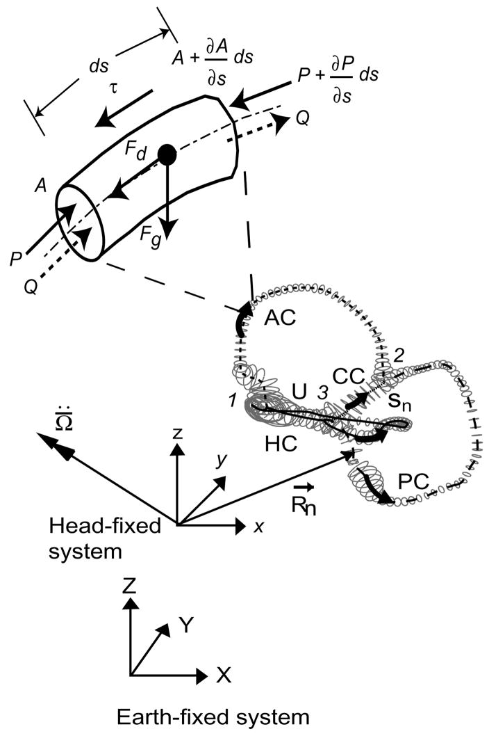
The main input to the model was the 3D geometry of the human membranous labyrinth, extracted from temporal bone histological sections through manual segmentation and adjusted for tissue shrinkage [14,26]. The reconstructed labyrinth consisted of five main segments: horizontal canal (HC), posterior canal (PC), anterior canal (AC), common crus (CC) and utricular vestibule (U). Curved centerlines (Sn) were defined to run along each labyrinth component. Tangent, normal, and binormal vectors were defined at points along the centerline. These formed local coordinate systems that served as a basis for data fitting of elliptical tubes to the reconstruction [30]. Data fitting consisted of selecting a thin 500 μm slice of data points perpendicular to the tangent vector at each center point, projecting the points into the normal-binormal plane and least squares fitting an ellipse to the selection. The final result was a parameterized surface reconstruction of the membranous labyrinth, shown in Fig. 1. The membranous labyrinth was oriented in a human head (Flash Fire Designs, Staunton, VA) according to stereotactic bony canal planes determined from 3D multiplanar CT measurements by Della Santina et al. [7].
Fig. 1.
Membranous labyrinth geometry. The centerlines of the membranous labyrinth geometry of the right ear used in the present model are illustrated with respect to the head-fixed (xyz) and earth-fixed (XYZ) co-ordinate systems. HC – horizontal (lateral) canal, PC –posterior canal, AC – anterior canal, CC – common crus, utricular section. The trajectories of R⃗n define the centerline coordinates sn and the vector is the angular acceleration of the head, both resolved in the head-fixed coordinate system. An expanded view of a short section of the canal (length ds) with a free-floating particle is shown. P represents pressure along the centerlines of the canal, τ is the shear stresses at the wall, Q is the endolymph volume displacement and A is the local cross-sectional area of the canal. Fg is the force due to gravito-inertial acceleration and Fd is the interaction drag force between the particle and the endolymph.
2.2. Biomechanics
Following the approach described previously [25], the membranous labyrinth was modeled as a rigid structure fixed firmly to the temporal bone and filled with viscous endolymph undergoing low Reynolds, number Poiseuille flow. The forces acting during BPPV on the endolymph are illustrated in Fig. 1 as a free-body diagram of a short canal segment. These forces arise due to the viscous interaction of endolymph and the free-floating particles, shear stresses acting at the duct wall and a pressure drop along the canal centerline. We assumed ideal Stokes’ drag on the particles and neglected the interaction between the particles and the membranous duct wall. Specific model equations are provided in the Appendix (from [26]). Model equations were solved in the time domain using a fifth-order Runga-Kutta-Fuehlberg method (Wavemetrics, Igor Pro).
2.3. Maneuvers
We applied the model to predict the location of particle debris within the labyrinth and cupulae volume displacements during the HC-BPPV diagnostic maneuver and CRPs. The following standard definitions were used to describe head rotations: pitch, rotation about an axis out the ear (head-fixed y-axis); roll, rotation about an axis out the eye (head-fixed x-axis); and yaw, rotation about an axis pointing out the top of the head (head-fixed z-axis).
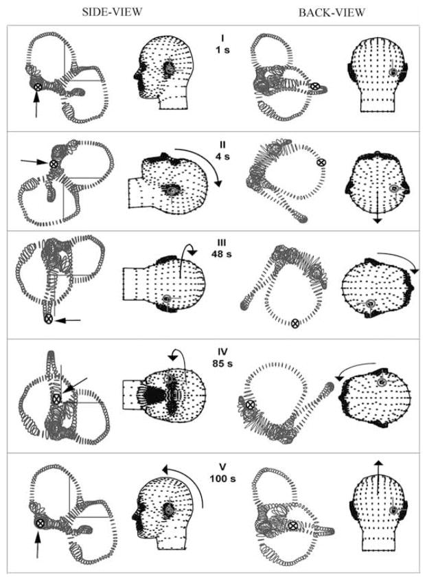
For the purpose of discussion, we defined a standard HC-BPPV diagnostic test consisting of four head rotations illustrated in Fig. 2. The upper body was quickly pitched backwards until the patient was in the supine position. After a brief delay, the head was rotated in yaw 90° toward the affected ear, and then 180° yaw in the opposite direction. We modeled these movements by defining the series of consecutive discrete rotation steps with the instantaneous rotation matrix at each time defined by R in Table 1 (R11 – R33 define the components of each 3 × 3 rotation matrix). The delay time is the time over which head is held stationary in space (until the nystagmus subsides) and movement time is the time over which a head rotation is executed. Each rotation was linearly interpolated with respect to the previous one and smoothed in time to generate continuous movements following Rajguru et al. [26].
Fig. 2.
Diagnostic maneuver for HC-BPPV. The orientations of the membranous labyrinth at five instants in time (I-V) for the diagnostic maneuver (re: gound-fixed system from the left-side Y-axis, and back X-axis). Rotation matrices corresponding to the maneuver are given in Table 1. Arrows and symbols (⊗) indicate the instantaneous particle location at five different instants in time.
Table 1.
Diagnostic maneuver for HC-BPPV
| Finish (s) tj | Move (s) Δ | Delay (s) Δ | R | R11 | R12 | R13 | R21 | R22 | R23 | R31 | R32 | R33 |
|---|---|---|---|---|---|---|---|---|---|---|---|---|
| t0 = 0 | 0 | 1 | R0 | 1 | 0 | 0 | 0 | 1 | 0 | 0 | 0 | 1 |
| t1 = 4 | 2 | 1 | R1 | 0 | 0 | −1 | 0 | 1 | 0 | 1 | 0 | 0 |
| t2 = 48 | 2 | 42 | R2 | 0 | −1 | 0 | 0 | 0 | −1 | 1 | 0 | 0 |
| t3 = 50 | 2 | 35 | R3 | 0 | 1 | 0 | 0 | 0 | 1 | 1 | 0 | 0 |
| t4 = 88 | 2 | 1 | R4 | 0 | 0 | −1 | 0 | 1 | 0 | 1 | 0 | 0 |
| t5 = 100 | 2 | 10 | R5 | 1 | 0 | 0 | 0 | 1 | 0 | 0 | 0 | 1 |
The model was also applied to study a 270° rotation and a 360° rotation CRP [15,16,20] designed to move the particle(s) from the HC lumen to the utricular vestibule (Table 2). The model 270° CRP movement consisted of three consecutive 90° yaw head rotations executed while the body was in the supine position, with each rotation toward the unaffected ear. The head was kept stationary in each position for 30–60 seconds allowing time for the particle(s) to fall under the action of gravity. A 360° CRP was also investigated (Fig. 3 [5]). For this, the head was first rotated in yaw 90° towards the affected ear while the subject was in supine position. The head was then turned 45° yaw towards the unaffected ear. These initial steps are key, as they facilitate the movement of the debris away from the ampulla. Subsequent steps are the same as those in the 270° CRP. The instantaneous rotation matrices (R) for the 360° CRP are provided in Table 2.
Table 2.
360°-rotation CRP for HC-BPPV
| Finish (s) tj | Move (s) Δ | Delay (s) Δ | R | R11 | R12 | R13 | R21 | R22 | R23 | R31 | R32 | R33 |
|---|---|---|---|---|---|---|---|---|---|---|---|---|
| t0 = 0 | 0 | 1 | R0 | 1 | 0 | 0 | 0 | 1 | 0 | 0 | 0 | 1 |
| t1 = 4 | 1 | 2 | R1 | 0 | 0 | −1 | 0 | 1 | 0 | 1 | 0 | 0 |
| t2 = 25 | 3 | 18 | R2 | 0 | −1 | 0 | 0 | 0 | −1 | 1 | 0 | 0 |
| t3 = 80 | 2 | 53 | R3 | 0 | 0.707 | −0.707 | 0 | 0.707 | 0.707 | 1 | 0 | 0 |
| t4 = 120 | 2 | 38 | R4 | 0 | 0 | 1 | 0 | −1 | 0 | 1 | 0 | 0 |
| t5 = 150 | 2 | 28 | R5 | 0 | −1 | 0 | 0 | 0 | −1 | 1 | 0 | 0 |
| t6 = 153 | 2 | 1 | R6 | 0 | 0 | −1 | 0 | 1 | 0 | 1 | 0 | 0 |
| t7 = 180 | 2 | 25 | R7 | 1 | 0 | 0 | 0 | 1 | 0 | 0 | 0 | 1 |
Fig. 3.
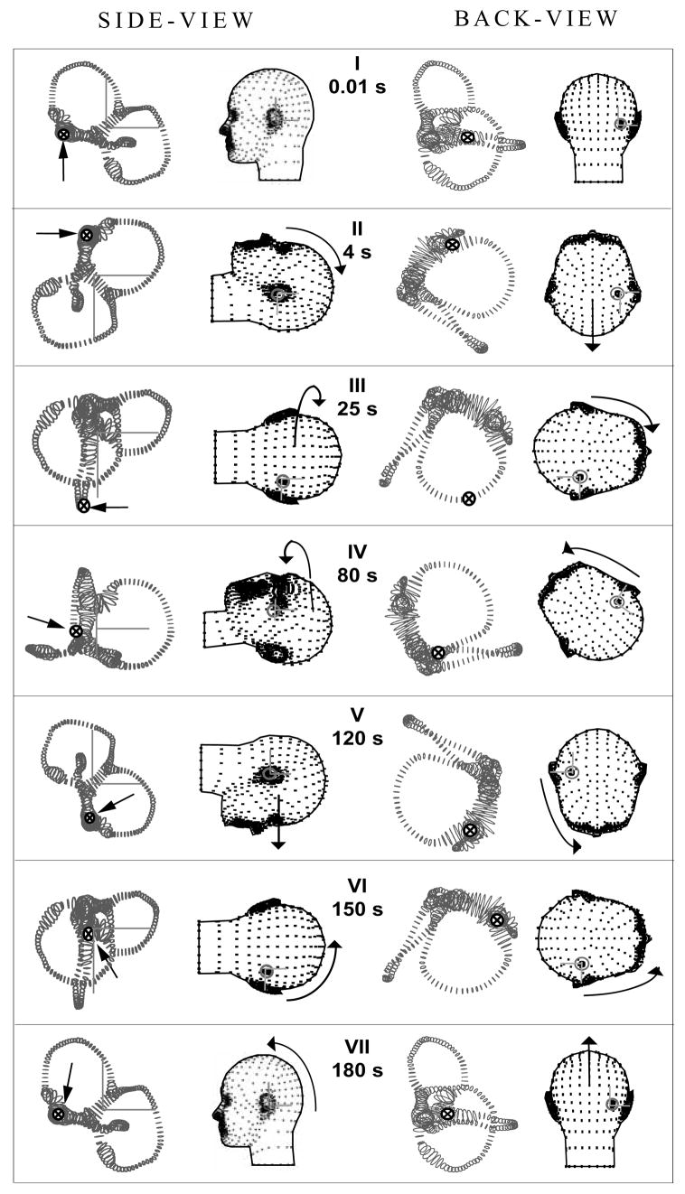
360° HC canalith repositioning procedure (CRP). Orientations of the head and membranous labyrinth for 7 instants of time defining the 360° CRP (see Table 2 for rotation matrix values). Same notation as Fig. 2. The arrows and symbols (⊗) indicate the location of the particles. Note that this CRP was effective in moving the particles from the canal lumen to the utricular vestibule.
In addition to estimating particle position during diagnostic and repositioning procedures, we applied the model to study the influence of particle size, number and initial location on cupular responses. Simulations were carried out for both the HC and PC variants of BPPV and their results were used to estimate and compare ocular nystagmus magnitude and temporal characteristics (Table 3).
Table 3.
Comparison of model predictions of latency-to-peak response, duration and estimated magnitude of nystagmus for canalithiasis condition due to various particle sizes for PC/HC variant of BPPV
| Size (μm) | Number of Particles | Initial Location | Latency to Onset (s) | Latency-to-Peak (s) | Duration of Non-physiological Response (s) | Estimated Nystagmus (°/s) |
|---|---|---|---|---|---|---|
| 5 | 62 | Ampulla | 20/17 | 75/42 | 84.44/80 | 34.42/28.72 |
| 7.5 | 18 | 8/11 | 33/22 | 48.15/40.50 | 29.48/22.41 | |
| 10 | 8 | 4/8 | 15/14 | 29.97/24.80 | 26.25/18.21 | |
| 12 | 5 | 3/6 | 11/11 | 21.79/17.70 | 23.98/16.21 | |
| 15 | 3 | 3/5 | 10/8 | 17.37/15.40 | 21.54/14.45 | |
| 18 | 1 | 3/5 | 6/6 | 8.69/4.70 | 9.77/6.85 | |
| 20 | 1 | 3/5 | 5/5 | 6.68/< 1 | 11.38/7.48 | |
| 5 | 62 | Canal Lumen | 4/< 1 | 35/11 | 81.0/63.1 | 30.73/22.91 |
| 7.5 | 18 | 4/< 1 | 16/4 | 38.12/30.70 | 25.31/16.92 | |
| 10 | 8 | 4/< 1 | 11/2 | 23.95/17.30 | 20.91/14.20 | |
| 12 | 5 | 4/< 1 | 10/1 | 17.29/10.80 | 18.48/13.89 | |
| 15 | 3 | 3/< 1 | 6/1 | 13.15/8.50 | 16.53/16.4 | |
| 18 | 1 | 4/< 1 | 5/< 1 | 4.59/2.40 | 7.58/8.46 | |
| 20 | 1 | 4/< 1 | 4/< 1 | 1.00/1.90 | 9.10/10.69 |
3. Results
3.1. Diagnostic maneuver – canalithiasis
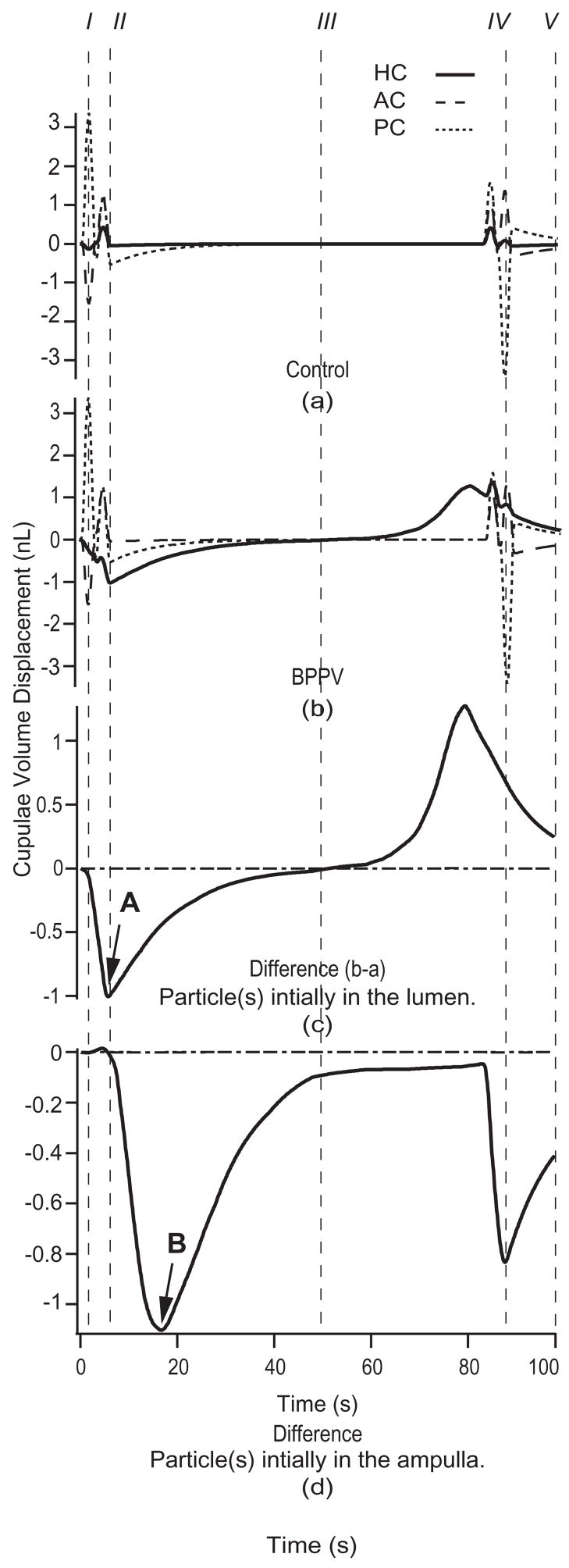
The location of particle debris, indicated by an arrow and denoted by the symbol ⊗, is shown in Fig. 2 during each head position of the HC-BPPV provocative maneuver. For this and subsequent simulations, a 6-particle aggregate (collective radius 12 μm, total mass = 0.117 μg) was initially positioned in the HC lumen (Fig. 2I). Figure 4 details the cupulae volume displacements evoked in response to the provocative maneuver for (a) a no-particle control and (b) canalithiasis conditions. The volume displacements predicted by the model for the HC are shown as solid curves. Figure 4(c), (d) show the difference between volume displacements in the canalithiasis and control conditions – a difference that corresponds to the pathological cupula displacement due to the presence of the particles. This pathological mechanical response estimated by the model would be expected to directly lead to pathological afferent input to the brainstem and clinically observed vestibular symptoms.
Fig. 4.
Canalithiasis responses to diagnostic maneuver. Cupulae volume displacements for the control (a) and the canalithiasis (b) conditions in response to the provocative maneuver (Fig. 2 and Table 1) when the particles were initially located in the HC lumen (response of HC – solid, PC – short dashed, AC – long dashed). I–V correspond to head positions illustrated in Fig. 2. Specific results were computed for 6 particles, each of 12 μm radius. The difference between the control and canalithiasis conditions is a measure of the pathological response. This difference is shown in the third panel (c) for the case when the particles were initially located in the HC lumen, and shown in the bottom panel (d) for the case when the particles were initially located in the HC ampulla. Note the increased latency (arrow B vs. A) when the particles are initially located in the ampulla vs. in the slender lumen of the canal.
The volume displacements of the PC and AC cupulae were essentially unaffected by the presence of particles in the HC (Fig. 4(c) and (d)). The pathological volume displacement of the HC cupula, however, was considerable. Note also that the latency-to-peak inhibitory response, computed as the time interval between provocative position achievement and peak cupula volume displacement, was less than one second (arrow A, Fig. 4c). It is interesting that this latency increases if the particles are initially located in the ampulla (arrow B, Fig. 4(d)) rather than in the canal lumen (4(c)). The long latency when the particles are initially located in the ampulla is predicted to be due to the time required for the particles to reach the narrow canal lumen. Figure 4 also illustrates that particles have the maximal effect on cupula displacements when moving within the slender lumen of the canal, and have a relatively small effect when they are free-floating within larger regions such as the ampulla and/or utricular vestibule.
3.2. Canalithiasis latency
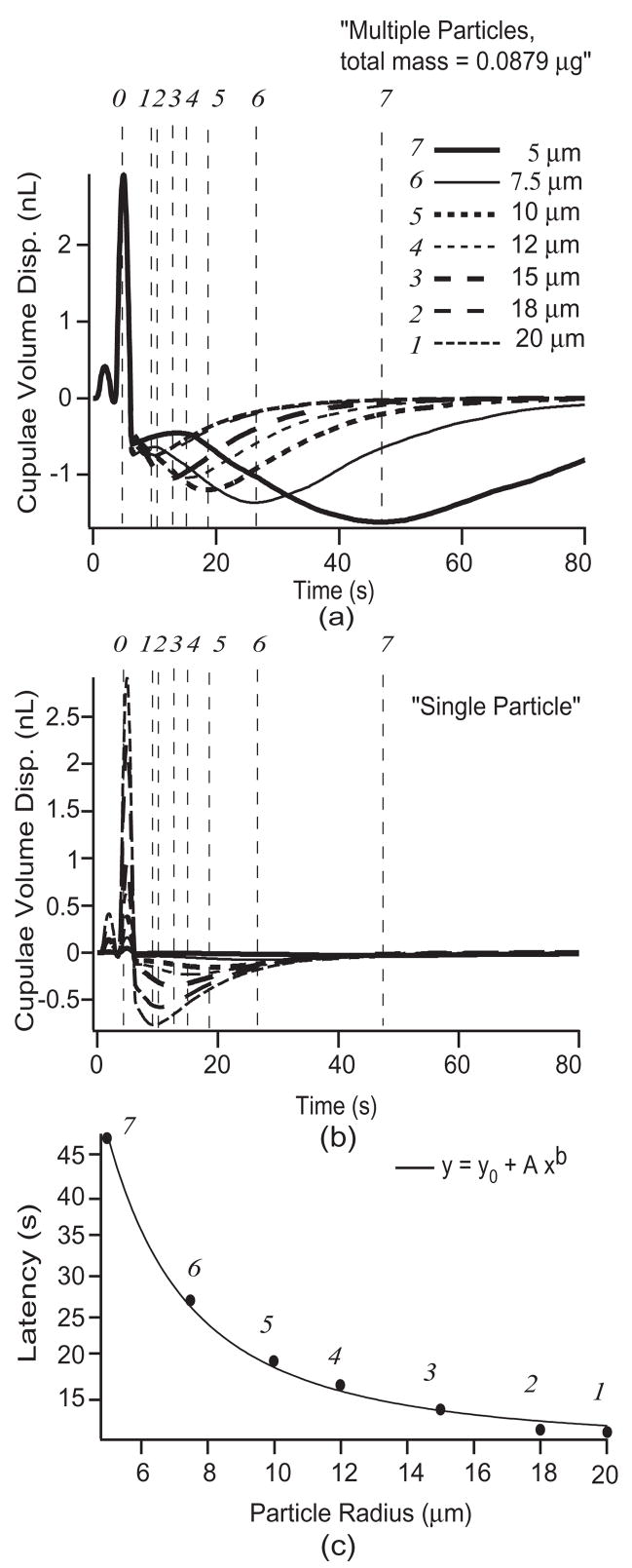
The latency-to-peak response is a distinctive feature of canalithiasis BPPV and warrants further mention. Since it remains unclear the number or size of particles involved in BPPV occurrences, we applied the model to predict latency changes as a function of particle dimensions and number. Latency was studied using particles with radii of 5, 7.5, 10, 12, 18, and 20 μm [6]. Responses during the provocative maneuver, with the particle(s) initially located within the HC ampulla, were predicted for multiple particles (Fig. 5a) with the total mass held constant at ~ 0.0879 μg [13] by varying the number of particles with changes in radii. The model was also used to predict the responses for a single particle of different radii mentioned above (Fig. 5b). The first vertical dashed line (denoted by 0 at the top of the figure) indicates the time at which the 90° provocative head position toward the affected side was achieved. Dashed lines labeled 1–7 indicate the incidences of peak HC cupula volume displacements predicted by the model. In general, an aggregate of smaller particles results in longer latencies and larger HC cupula displacements. The middle panel (b) shows the influence of a single particle. In this case, single small particles give rise to longer latencies but a much smaller magnitude of response than a single large particle. This is because large particles fall faster and quickly come to rest at the lowest position within the HC lumen. This rapid particle movement does not allow the cupula sufficient time to come to its steady-state position because the viscous fluid in the slender duct limits the magnitude of the response. This dependence on particle size was expected since the particle terminal free-fall velocity at low Reynolds’ number varies in proportion to the square of the radius. Consequently, the time at which peak cupula volume displacement occurs varies as ~1/a2 as observed from the curve fit using a power function (Fig. 5c).
Fig. 5.
Canalithiasis response latency. HC cupula volume displacements estimated in response to the diagnostic maneuver (Fig. 2) for (a) multiple particles of various radii (constant total mass of 0.0879 μg) and (b) single particle of various radii. The provocative position was achieved at the time denoted by (φ). Points (1–7) denote the peak HC cupula volume displacement for the particle sizes indicated. Bottom panel (c) shows the latency to the peak cupula volume displacement (latency times of points 1–7) as a function of particle size. The latency varied as the inverse of the radius squared (~1/a2; curve fit parameters: b = −2, A = 961, y0 = 9.1).
3.3. Canalithiasis CRP
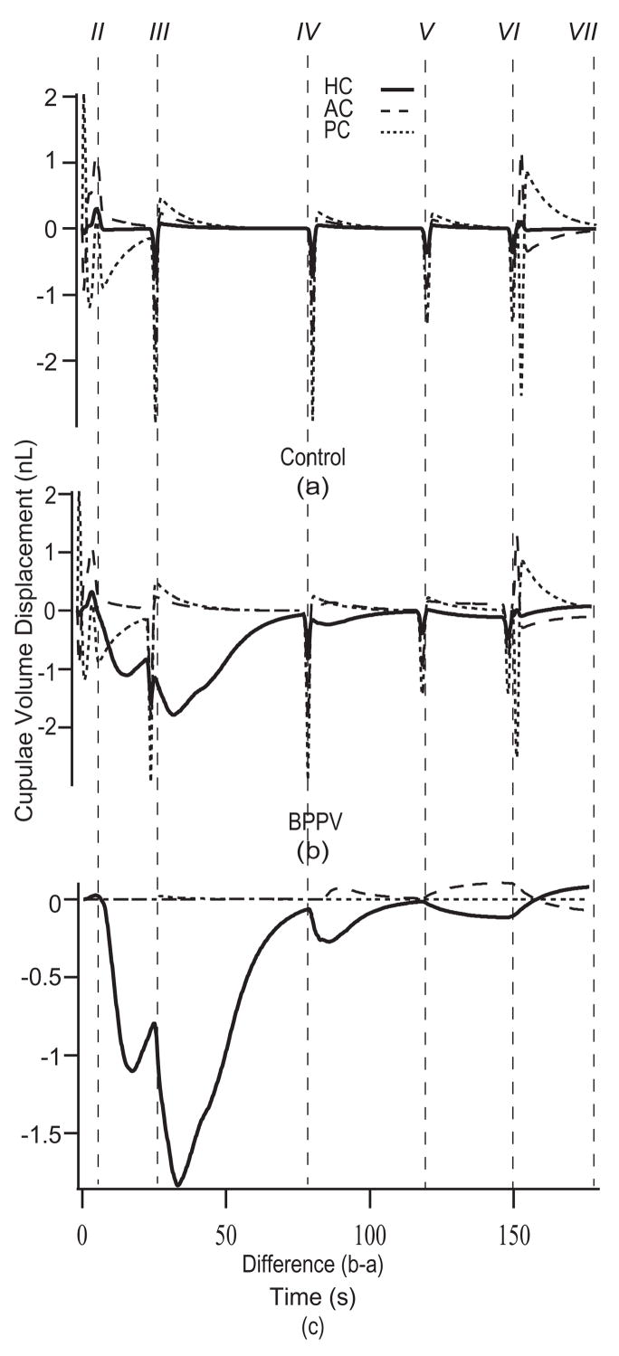
The model was applied to estimate cupula and particle displacements for 270° and 360° CRPs. The 270° CRP was successful in relocating debris to the utricle if the particles were initially located in the canal lumen, but failed when the particles were initially located in the HC ampulla. Therefore we propose a 360° CRP, shown in Fig. 3, that was successful in simulations regardless of initial particle location. For this CRP, the patient is first placed in the supine position (Fig. 3, II) and then subjected to four consecutive rotations. The first 90° rotation toward the affected ear (Fig. 3, III) was designed to move the particle(s) from the HC ampulla into the slender lumen of the canal. The remaining steps (Fig. 3, IV, V, VI) define a rollover sequence toward the unaffected ear designed to move the particles along the canal lumen and ultimately into the utricle. The first rotation toward the affected ear is unconventional, but simulations showed that this step is essential when particles are initially located deep within the ampulla. Predicted responses of all three canals during the 360° CRP are shown in Fig. 6. Differences between the (a) control and (b) canalithiasis condition are shown in the bottom panel (c). This difference is the fraction of the response that is not present in the control condition and therefore represents the pathological response. Excitatory HC stimulation estimated by the model in the initial 90° head turn would be expected to lead to the characteristic horizontal ocular nystagmus observed clinically. Subsequent rotations result in similar responses, though with shorter latencies. The influence of the particles is relatively small once positioned within utricular vestibule, since this region has a large cross sectional area.
Fig. 6.
Cupulae volume displacements during the CRP. Cupulae volume displacements estimated for the control (a) and the canalithiasis BPPV (b) conditions in response to the 360° CRP (HC – solid, PC – short dashed, AC – long dashed). Instants in time labeled II-VII correspond to the head positions illustrated in Fig. 3. The difference between the canalithiasis and control volume displacements (i.e. pathological response) is shown in (c). Specific results were computed for 6 particles, each of 12 μm radius.
3.4. Diagnostic maneuver – cupulolithiasis
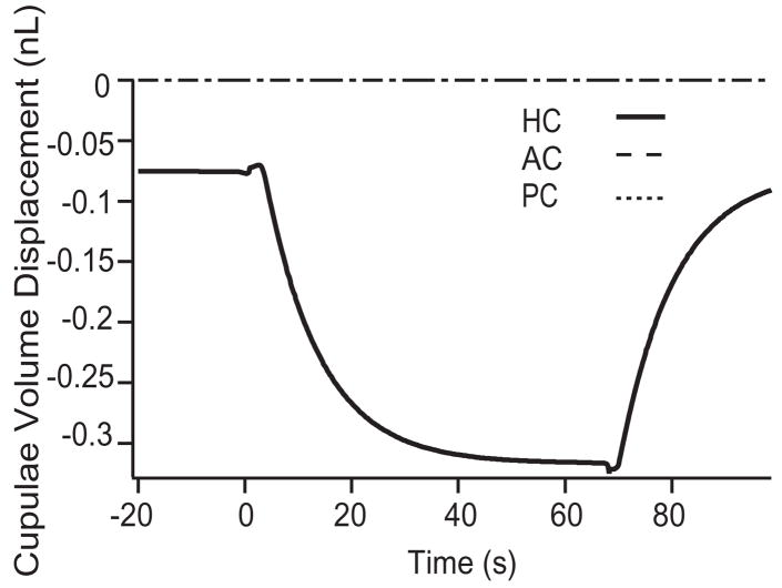
We also applied the model to investigate cupulolithiasis by adhering 6 particles, of 12 μm each, to the HC cupula. Figure 7 shows cupulae volume displacements of the three canals in the control and cupulolithiasis conditions in response to the diagnostic maneuver (Fig. 2). Maintained pathological activation of the HC was predicted once the provocative position was achieved. The peak displacement of the cupula (~320 pL) was less than that predicted under the same conditions during canalithiasis (~1200 pL). This difference arises in the model due to a force amplifying lever-effect that occurs in canalithiasis as the particles move from the ampulla into a smaller cross-section of the canal lumen, an occurrence that is absent in cupulolithiasis [13,28].
Fig. 7.
Cupulolithiasis responses to diagnostic maneuver. The difference between the cupulae volume displacement estimated in the control condition vs. the cupulolithiasis condition is shown for the HC diagnostic maneuver illustrated in Fig. 2. As expected, the model predicts maintained mechanical stimulation of the HC cupula when the head is held in the provocative position.
In addition to predicting cupular volumetric displacements, the model was also used to estimate ocular nystagmus evoked by diagnostic maneuvers in control and BPPV canalithiasis conditions. For this, we computed the transfer function between cupula volume displacement and slow-phase angular eye velocity for sinusoidal angular head oscillation in the control condition at 2 Hz. This yielded ~53 pL cupula displacement for each 1 deg/s of angular head velocity. Therefore, a pathological cupula displacement of 53 pL would be estimated to induce pathological nystagmus of ~1°/s. For comparison to clinical data, we used a threshold of 9°/s ocular nystagmus (i.e. 473 pL cupula volume displacement) to estimate nystagmus onset latency and duration. Results are summarized in Table 3 for various particle sizes (radii, μm), numbers, and initial positions (in the ampulla or lumen of the canal). The table compares results for HC-BPPV (present manuscript) to previous model predictions for PC-BPPV [20]. Latencies are reported relative to achievement of the provocative position. Both onset latency (to reach 9°/s threshold) and latency-to-peak response are shown. Duration of the non-physiological response indicates the total time over which the estimated nystagmus was above the 9°/s threshold. Under most conditions, the model predicts a shorter onset latency for HC-BPPV vs. PC-BPPV. This occurs because the orientation and geometry of the membranous labyrinth makes it likely for particles in the PC to initially reside within the PC ampulla, whereas particles in the HC are likely to initially reside in the HC canal lumen.
4. Discussion
The present biomechanical model was developed to provide a quantitative basis for the diagnosis and treatment of HC-BPPV, and to provide an understanding of differences between HC-BPPV vs. PC-BPPV. Ocular nystagmus onset latency during provocative tests is a key difference between HC- vs. PC-BPPV observed clinically. The present simulations indicate that this difference is probably due to the initial location of canalithiasis particles prior to administration of the provocative diagnostic test. In PC-BPPV the particles are likely to be initially located in the PC ampulla due to the geometry and orientation of the labyrinth in the head [26]. In contrast, there is no compelling reason why particles in HC-BPPV would be initially located in the HC ampulla and, indeed under clinical conditions, may be inadvertently displaced to the HC lumen during the diagnostic test. For particles initially located within the ampulla, there would be a delay time during which the particles move from the larger-cross sectional area of the ampulla into the narrow canal lumen and hence, a longer latency relative to particles initially located in the lumen. The relatively short onset latency (< 1–3 s) of HC-BPPV relative to PC-BPPV may simply reflect the initial location of the particles in the lumen vs. the ampulla. For the special case of HC-BPPV when the particles are initially located in the ampulla, the model indicates that the use of a 360° CRP to treat canalithiasis may increase the likelihood of clinical success relative to a 270° CRP.
The model was also applied to estimate the time course of pathological ocular nystagmus that would be expected to occur under conditions of HC-BPPV. For example, the model predicts ~ 1264 pL of cupula displacement for the canalithiasis case in response to the provocative maneuver (using particle mass ~ 0.117 μg, 6 particles, radius 12 μm each) – a response that would be expected to produce slow-phase eye movements with a velocity of approximately 22°/s. Similarly, for a pathological mass of ~0.0877 μg (62 particles, radius 5 μm each), the model predicts the peak HC cupula displacement of ~1520 pL and a slow-phase eye velocity on the order of 26°/s. These velocity estimates fall within the clinically observed range of 17°/s–72°/s [2] and therefore provide confidence in the modeling approach. Changing the number and/or sizes of particles would of course, expand the range.
Although the model is quite detailed in its attention to the geometry of the membranous labyrinth, there are several limitations that should be noted. The model assumes low-frequency head movements, does not account for the interaction of the particle(s) with the membranous wall, and is strictly biomechanical in nature. It has been shown previously that neglecting the wall interactions is reasonable when the particles are located near the center of the canal lumen, but it will overestimate the force transmitted to the endolymph for small particles sliding or rolling along the canal wall [28]. Bungay and Brenner [3] predict the theoretical pressure drop due to a sphere settling in a vertical tube as a function of particle lateral position (radius of sphere (a)/distance from wall of tube (h)) and particle-to-tube radius ratio (a/R). Experimental data available for larger particles are consistent with the theoretical model of [3] (a/R = 0.13–0.53 [11]), but are not available for smaller particles. For very small particles or particles in the ampulla (a/R ~0.05) our model would overestimate the pressure drop by approximately 90% when the particles are sliding along the wall (a/h = 1). And for the same case if the particle is one diameter away from the wall (a/h = 0.5), the model would overestimate the pressure drop by about 60%. However, for most cases of BPPV i.e., for larger particles or particles in smaller canal lumen (a/R ~0.11–0.13), our model would overestimate the pressure drop by only 10% when a/h = 0.5 and by 70% for a/h = 1. Qualitatively this means that small particles in the vicinity of the canal wall would generate cupula displacements with longer latencies and smaller magnitudes than predicted by the present simplified model. This would be similar to adjusting the particle size to a smaller “effective” diameter in the model. Also, the pressure (or form) drag arising from the pressure difference that results from the diversion of the fluid flow around the small spheres can be assumed small (unless the particle is sliding along the canal wall). Although theoretically contact with the canal wall would bring the particles to rest since infinite force is then required to produce motion of the spheres, it is unlikely to be observed in practice (as discussed by [3] and [10], owing to the breakdown in assumptions of perfect smoothness of the rigid surfaces and the integrity and constancy of the physical properties of fluid phase). Therefore, for simplicity, we neglected wall interaction in the present model with the understanding that predicted responses are approximate. A neural model was not included, so results do not predict the afferent responses or eye movements directly. Eye movements were estimated from cupula displacements by assuming a perfect vestibulo-ocular reflex with a gain near unity. Although the model can be applied to any individual human geometry, predictions shown here are based on one example subject. However, even with these simplifications both the latency and the magnitude of the predicted pathological responses fall within the range observed clinically. Differences between HC-BPPV and PC-BPPV are also consistent with clinical observations, further supporting canalithiasis and cupulolithiasis as common origins of BPPV.
Acknowledgments
This work was supported by the National Institutes of Health NIDCD R01-DC006685.
Appendix. Model Equations
The endolymph volume displacement, Qn, for each nth segment of the membranous labyrinth was modeled using:
| (1) |
where mn, cn and kn were computed using [4]
| (2) |
| (3) |
and
| (4) |
A(s) is the cross-sectional area as a function of the centerline coordinate s, ρ is the mass density, γ is the shear stiffness and μ is the viscosity (values of the physical parameters are provided in Table 4). The coefficient lambda; = 8π, which is appropriate for low frequency head movements used in the present CRP movements and provocative tests. The cupulae were modeled as poroelastic, also using Eq. (1) but noting that the pressure difference is the drag between the fluid and solid phases rather than the fluid pressure [25]
Table 4.
Physical parameters
| Parameter | Value | Units | |
|---|---|---|---|
| ρe | endolymph density | 1.0 | g.cm−3 |
| ρe | endolymph viscosity | 8.5 × 10⁻³ | dyn.s−1.cm−1 |
| ρc | cupula density | 1.0 | g.cm−3 |
| γc | cupula shear stiffness | 3.7 | dyn.cm−2 |
| h | cupula thickness | 3.08 × 10⁻² | cm |
| Γ | permeability coef. | 2.0 × 10⁵ | dyn.s−1.cm− |
| ρs | particle density | 2.7 | g.cm−3 |
| a | nom. particle radius | 1.2 × 10⁻³ | cm |
| Ns | nom. particle number | 6 | |
| (5) |
Qe and Qc are the volume displacements of the cupula and endolymph respectively and Γ is the inverse Darcy coefficient. The forcing term is the sum of inertial and particle components:
| (6) |
where is the local tangential acceleration of the duct due to angular acceleration of the head ( ) (resolved into the head-fixed frame) [25]. The second term accounts for the force on the endolymph from the particle [20]
| (7) |
a is the radius of the particle(s),g→ is the gravitational acceleration, n̂ is the unit normal directed tangent to the duct centerline and Ns is the number of particles. The frontal area of a single particle is As = πa2 and the area of the canal lumen at the position of the particle is . This equation is nonlinear due to the fact that local cross-sectional area varies as the particle(s) moves within the labyrinth. The coordinate ξ(t) defines the centerline “s” position of the particle(s). The acceleration of the particle(s) tangent to the centerline is
| (8) |
where ms is the mass of the particle. For cupulolithiasis, the particle velocity matches the endolymph velocity such that and the second term in Eq. (7) is zero.
Equations for each segment were combined to obtain a coupled set of ordinary differential equations of the form [25]
| (9) |
where C is the damping matrix, K is the stiffness matrix and F⃗ is the forcing vector. We have neglected the mass matrix M due to the low frequencies of interest in the present simulations. The dependent variables are endolymph (Q⃗e)and cupulae (Q⃗c)volume displacements
| (10) |
The damping and stiffness matrices are
| (11) |
and
| (12) |
The above equations Eqs (1–4), (6–12) account for all three canals, common crus and utricle. The complete damping and stiffness matrices are provided in Rajguru et al. [20] The forcing vector is:
| (13) |
References
- 1.Baloh RW, Honrubia V, Jacobson K. Benign positional vertigo: clinical and oculographic features in 240 cases. Neurology. 1987;37:371–378. doi: 10.1212/wnl.37.3.371. [DOI] [PubMed] [Google Scholar]
- 2.Baloh RW, Jacobson K, Honrubia V. Horizontal semicircular canal variant of benign positional vertigo. Neurology. 1993;43:2542–2549. doi: 10.1212/wnl.43.12.2542. [DOI] [PubMed] [Google Scholar]
- 3.Bungay PM, Brenner H. Pressure drop due to the motion of a sphere near the wall bounding a poiseuille flow. J Fluid Mech. 1973;60:81–96. [Google Scholar]
- 4.Damiano ER, Rabbitt RD. A singular perturbation model of fluid dynamics in the vestibular semicircular canal and ampulla. J Fluid Mech. 1996;307:333–372. [Google Scholar]
- 5.De la Meilleure G, Dehaene I, Depondt M, Damman W, Crevits L, Vanhooren G. Benign paroxysmal positional vertigo of the horizontal canal. J Neurol Neurosurg Psychiatry. 1996;60:68–71. doi: 10.1136/jnnp.60.1.68. [DOI] [PMC free article] [PubMed] [Google Scholar]
- 6.De Vries H. The mechanics of the labyrinth otoliths. Acta Otolaryngol. 1951;38:262–273. doi: 10.3109/00016485009118384. [DOI] [PubMed] [Google Scholar]
- 7.Della Santina CC, Potyagaylo VL, Migliaccia AA, Minor LB, Carey JP. Orientation of human vestibular labyrinth semicircular canals measured by 3D multiplanar CT; ARO. Twenty-seventh Annual Mid-winter Research meeting; 2004. [Google Scholar]
- 8.Epley JM. The canalith repositioning procedure: for treatment of benign paroxysmal positional vertigo. Otolaryngol Head Neck Surg. 1992;107:399–404. doi: 10.1177/019459989210700310. [DOI] [PubMed] [Google Scholar]
- 9.Furman JM, Cass SP, Briggs BC. Treatment of benign positional vertigo using heels-over-head rotation. Ann Otol Rhinol Laryngol. 1998;107:1046–1053. doi: 10.1177/000348949810701209. [DOI] [PubMed] [Google Scholar]
- 10.Goldman AJ, Cox RG, Brenner H. Slow viscous motion of a sphere parallel to a plane wall. I. Motion through a quiescent fluid. Chem Eng Sci. 1967;22:637–651. [Google Scholar]
- 11.Goldsmith HL, Mason SG. The flow of suspensions through tubes. I. Single spheres, rods and discs. J Colloid Sci. 1962;17:448–476. [Google Scholar]
- 12.Hall SF, Ruby RR, McClure JA. The mechanics of benign paroxysmal vertigo. J Otolaryngol. 1979;8:151–158. [PubMed] [Google Scholar]
- 13.House MG, Honrubia V. Theoretical models for the mechanisms of benign paroxysmal positional vertigo. Audiol Neurootol. 2003;8:91–99. doi: 10.1159/000068998. [DOI] [PubMed] [Google Scholar]
- 14.Ifediba MA, Hullar TE, Rajguru SM, Rabbitt RD. Three-dimensional Reconstruction of the Human Membranous Labyrinth; ARO. Twenty-seventh Annual Mid-winter Research meeting; 2004. [Google Scholar]
- 15.Lempert T. Horizontal benign positional vertigo. Neurology. 1994;44:2213–2214. doi: 10.1212/wnl.44.11.2213-a. [DOI] [PubMed] [Google Scholar]
- 16.Lempert T, Tiel-Wilck K. A positional maneuver for treatment of horizontal-canal benign positional vertigo. Laryngoscope. 1996;106:476–478. doi: 10.1097/00005537-199604000-00015. [DOI] [PubMed] [Google Scholar]
- 17.Lim DJ. Otoconia in health and disease. A review. Ann Otol Rhinol Laryngol. 1984;112(Suppl):17–24. doi: 10.1177/00034894840930s404. [DOI] [PubMed] [Google Scholar]
- 18.McClure JA. Horizontal canal BPV. J Otolaryngol. 1985;14:30–35. [PubMed] [Google Scholar]
- 19.Nuti D, Vannucchi P, Pagnini P. Benign paroxysmal positional vertigo of the horizontal canal: a form of canalolithiasis with variable clinical features. J Vestib Res. 1996;6:173–184. [PubMed] [Google Scholar]
- 20.Nuti D, Agus G, Barbieri MT, Passali D. The management of horizontal-canal paroxysmal positional vertigo. Acta Otolaryngol. 1998;118:455–460. doi: 10.1080/00016489850154559. [DOI] [PubMed] [Google Scholar]
- 21.Oas JG. Benign paroxysmal positional vertigo: a clinician’s perspective. Ann N Y Acad Sci. 2001;942:201–209. doi: 10.1111/j.1749-6632.2001.tb03746.x. [DOI] [PubMed] [Google Scholar]
- 22.Otsuka K, Suzuki M, Furuya M. Model experiment of benign paroxysmal positional vertigo mechanism using the whole membranous labyrinth. Acta Otolaryngol. 2003;123:515–518. doi: 10.1080/0036554021000028094. [DOI] [PubMed] [Google Scholar]
- 23.Pagnini P, Nuti D, Vannucchi P. Benign paroxysmal vertigo of the horizontal canal. ORL J Otorhinolaryngol Relat Spec. 1989;51:161–170. doi: 10.1159/000276052. [DOI] [PubMed] [Google Scholar]
- 24.Parnes LS, McClure JA. Free-floating endolymph particles: a new operative finding during posterior semicircular canal occlusion. Laryngoscope. 1992;102:988–992. doi: 10.1288/00005537-199209000-00006. [DOI] [PubMed] [Google Scholar]
- 25.Rabbitt RD. Directional coding of three-dimensional movements by the vestibular semicircular canals. Biol Cybern. 1999;80:417–431. doi: 10.1007/s004220050536. [DOI] [PubMed] [Google Scholar]
- 26.Rajguru SM, Ifediba MA, Rabbitt RD. Three-dimensional biomechanical model of benign paroxysmal positional vertigo. Ann Biomed Eng. 2004;32:831–846. doi: 10.1023/b:abme.0000030259.41143.30. [DOI] [PubMed] [Google Scholar]
- 27.Schuknecht HF. Positional vertigo: clinical and experimental observations. Trans Am Acad Opthalmol Otol. 1962;66:319–331. [PubMed] [Google Scholar]
- 28.Squires TM, Weidman MS, Hain TC, Stone HA. A mathematical model for top-shelf vertigo: the role of sedimenting otoconia in BPPV. J Biomech. 2004;37(8):1137–1146. doi: 10.1016/j.jbiomech.2003.12.014. [DOI] [PubMed] [Google Scholar]
- 29.Thalmann R, Ignatova E, Kachar B, Ornitz DM, Thalmann I. Development and maintenance of otoconia: biochemical considerations. Ann N Y Acad Sci. 2001;942:162–178. doi: 10.1111/j.1749-6632.2001.tb03743.x. [DOI] [PubMed] [Google Scholar]
- 30.Varberg D, Purcell EJ. Calculus. Prentice-Hall Inc; New Jersey: 1997. [Google Scholar]


