Abstract
We utilized a microfluidic device with hydrodynamic flow focusing geometry to produce uniform agarose droplets in the range of 50 to 110 μm. The transport property of the thermally gelled particles was tailored by layer-by-layer (LBL) polyelectrolytes coating on the surface and was measured via the release rates of Rhodamine B. The mechanical strength of the capsules was further enhanced by a coating of silica nano-particles in addition to polyelectrolyte coatings. We demonstrated that yeast cells can be successfully encapsulated into agarose capsules.
INTRODUCTION
Encapsulation of living cells provides a new technology to overcome various medical problems, such as in the treatment of diabetes,1 hormone or protein deficient diseases,2, 3 and cancers.4 The idea of using ultra-thin polymer membrane microencapsulates for the immunoprotection of transplanted cells was proposed in 1964 by T.M.S. Chang.5 Cell encapsulation aims to protect transplanted cells from immunorejection without the use of immunosuppressive drugs. After transplantation, cells inside capsules can survive and produce therapeutic substances. However, for the application of cell encapsulation techniques some technological and biological limitations still exist, such as production of uniform capsules, and lack of clinical grade polymers.6
Agarose has long been widely used to encapsulate cells.7 It is a type of naturally occurring polysaccharides extracted from seeweeds. After being dissolved in water at high temperature, agarose solution can be cooled to form a transparent gel. The efficiency of agarose microcapsules for cell therapy has been demonstrated by both allo-transplantation and xeno-transplantation of pancreatic islets.8, 9, 10 The general method for preparing cell-enclosing agarose microcapsules is based on water-in-oil emulsion, which is followed by a reduction in the temperature to allow gellation of the agarose droplets. In general, the agarose droplets are produced by dispersion of agarose aqueous solution-in-oil via mechanical stirring or shaking. However, the capsules obtained usually posses a wide size distribution using this method.11, 12 Sakai S. et al. developed a method using droplet breakup in a coflowing stream for preparing agarose capsules.13, 14 They enclosed mammalian cells in subsieve-size capsules with the diameter ranging from 40 μm to 250 μm.
Microfluidics is a technology that involves the fabrication of microscale channels, valves and sensors. In last decades with the development of microfabrication techniques, the application of microfluidics techniques has increased rapidly in biotechnology.15, 16, 17 We used a microfluidics device with flow focusing geometry18, 19, 20 to generate agarose capsules and also used to encapsulate yeast cells. This method produced cell-enclosing microcapsules with a narrow size distribution. Also, the diameter of the microcapsule produced is much smaller than the conventional emulsion method, which results in an increase in surface-to-volume ratio, mechanical strength, and improved ability of nutrients diffusion. In this letter, we demonstrate the ability to tailor two important characteristics of these capsules6, 21 a) transport property and b) mechanical stability, by depositing the microcapsules surface with multilayers of polyelectrolytes by LBL self-assemble method,22 and a layer of nano silica particles. The transport properties and mechanical stability of the obtained capsules were measured.
MATERIALS AND METHODS
Materials
Agarose type IX-A with ultra-low gelling temperature (≤17 °C at 1.5% weight concentration in water), poly(sodium 4-styrene sulfonate, MW 70,000) (PSS), poly(allylamine hydrochloride) (PAH), 20 nm Ludox silica particles and light mineral oil were purchased from Sigma-Aldrich (Milwaukee, WI). Microfluidics devices were fabricated from poly(dimethylsiloxane) (PDMS) using a Sylgard 184 silicone elastomer kit (Dow Corning, Midland, MI). Yeast extract powder (YPD), peptone and glucose were purchased from Acros Organics. YPD medium used for growing yeast cells contained 2% bacteriological peptone, 1% yeast extract, 2% glucose and 1.5% agar (Sigma-Aldrich).
Agarose droplets generation
PDMS based microfluidics devices were fabricated using soft lithography process.23 Briefly, a thin layer of photoresist was created on the silicon wafer by spin-coating. The pattern of the microchannels was generated using AutoCAD software and transferred into a mask by high resolution laser printing. After photoresist being exposed to the UV light and developed, the pattern was transferred to the silicon wafer. Then PDMS mixture was poured onto the wafer and cured. Finally, the PDMS block with microchannel pattern on the surface was pealed off and sealed to a glass slide via a think layer plasma etching.
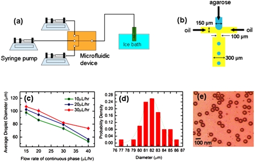
Microfluidics devices with flow focusing geometry design18, 19, 20 were used to produce monodisperse water-in-oil emulsion. The design of the microchannels is sketched in Figs. 1a and 1b. The size of the orifice is 100 μm. The aqueous phase was introduced through the center channel. Two streams of oil phase were injected via side channels. The oil and aqueous phases forged an interface right before the orifice. Because of the hydrophobic characteristics of the PDMS channel walls, aqueous thread was surrounded by continuous oil phase. This geometry resulted in hydrodynamics focusing of coaxial flow. The aqueous thread was dynamically unstable and it was pinched off into droplets into the outlet channel. When the flow was in the steady state, the size of droplets produced was uniform.
Figure 1.
Production of uniform agarose micro-gel capsules. (a) Experimental setup for generating agarose gelled particles. Agarose solution pinches into droplets in the microfluidic device. The droplets are collected in a glass vial placed in an ice bath to initiate the gelation of agarose (b) Schematic of the microfluidics device with flow focusing geometry producing agarose droplets. Agarose solution is introduced into the center channel and two streams of oil are flowed into two side channels. (c) Variation of droplet size with the flow rates of oil and aqueous phases (d) Droplet size distribution when oil flow rate was 30 μl∕h and aqueous flow rate was 20 μl∕h. Dotted line represents the Gaussian fit. Drop diameter is 82±2.9 μm (e) Micrograph of gelled agarose particles.
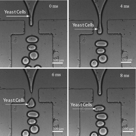
Experimental setup for cell encapsulation using microfluidics device is shown in Fig. 2. Yeast cell suspension was prepared and 2% wt agarose were added. The cell suspension was then introduced through the center channel. Cell-enclosing microcapsules of uniform size were generated. Agarose microcapsules containing cells were collected in a glass vial. Gelation of the droplets was initiated by cooling the sample using an ice bath.
Figure 2.
Yeast cells encapsulation in agarose capsules captured by a fast camera. The production rate of the microcapsule was about 100 Hz. Frame rate of the fast camera is 2200 frames per second. The concentration of yeast suspension measured at 600 nm optical density is 5×10⁸ cells∕ml. The oil flow rate was 30 μL∕hr and agarose flow rate was 20 μL∕hr.
Transport properties
To the agarose suspension, 0.1 wt % of PSS was added to introduce a partial negative surface charge. To form a polymer coating on the surface of agarose gel particles, the particles were collected and exposed to polyelectrolyte solutions with opposite charge (PSS, 0.5 wt %, pH 4.5 and PAH, 0.5 wt %, pH 4.5) for 5 min followed by a washing in water for 2 minutes to remove superficial polyelectrolytes. The coating procedure was repeated to form 5 layers of coating. To measure the transport property, agarose particles with and without coating were presoaked in 0.0005 M Rhodamine B solutions for 2 days. The particles were then washed with water and 0.1 gm of microcapsules was transferred placed into a 10 ml of blank solution (water). At certain time interval, 3 ml of blank solution was collected and the release of Rhodamine B was monitored via the increase in the fluorescence intensity. The effective diffusion coefficients of each capsule were determined by the nonlinear least-squares method from the following equation,24 which was derived under the assumptions that the concentration of the solute in the solution is uniform, the volume of the solution is finite, and the structure of the gel particles is homogeneous:
| (1) |
where R is the diameter of the gel bead, t is time, C0 is the initial concentration of the solute, C is the concentration of the solute at t; α is the volume fraction of the agarose particles in the solution. α=NVb∕V0, where N is the number of particles, Vb is the volume of particles, V0 is the volume of solution. qn is defined through .
Mechanical properties
To further increase the mechanical stability of the gel particles, after multilayer of polyelectrolyte coating, an additional layer of silica nano-particle was deposited by placing gel particles into a suspension of Ludox silica particles (60 mM) for 1 hour. The mechanical strength of the particles with no polymer coating, with 5-layer polymer coating, and with 5-layer polymer plus silica coating was investigated by shaking 50 agarose particles in 10 ml of Phosphate buffer solution at pH 7.4 using orbital shaker (C25 Classic Series. New Brunswick Scientific, NJ, USA) with 200 rpm at 37 °C for 16 days. The ruptured particles were counted at selected intervals of time.
RESULTS AND DISCUSSION
Different droplet sizes were obtained by varying relative flow rates of mineral oil and agarose solutions. For each flow rate of agarose solution, droplet diameters are measured by varying oil flow rates. Fig. 1c plots the diameters of the agarose microcapsules produced by flowing 2 wt % agarose aqueous solutions into the microchannel at flow rates of 10, 20 and 30 μL∕h. For a given agarose flow rate, smaller droplets were produced at higher oil flow rates. The flow rate of the mineral oil was varied from 15 to 40 μL∕h. For example, at 30 μL∕h agarose solution flow rate, the diameter of the droplets produced in oil with flow rate of 15 μL∕h was about 110 μm in diameter, while that produced in oil with flow rate of 40 μL∕h was about 75 μm. On the other hand, higher agarose flow rates at any fixed oil flow rate produced bigger dropets. For oil flow rate of 40 μL∕h, when agarose solution flow rate was 30 μL∕h, the droplet diameters obtained were about 80 μm. When agarose solution flow rate was reduced to 10 μL∕h, the droplet diameters reduced to 60 μm.
The size distribution of the agarose droplets was obtained with oil flow rate of 30 μL∕h and agarose flow rate of 30 μL∕h [Fig. 1d]. The droplets have an extremely narrow size distribution with standard deviation about 4%. Figure 1e shows the image of collected agarose gel particles under a Nikon inverted microscope (Eclipse TE2000-U). In our experiment, the device produced monodisperse droplets with excellent repeatability under identical conditions. The production of the droplets is at a rate of 100 Hz. Agarose suspension, 2 wt %, with yeast cells (5×10⁸ cells∕ml, measured at OD600 nm) was introduced in the center channel and the cells were encapsulated in gelled agarose particles. The process was captured by a high speed camera (Phantom 4.2, Vision Research, Wayne, New Jersey) with frame rate of 2200 frames∕second [Fig. 2].
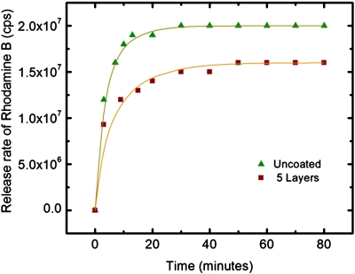
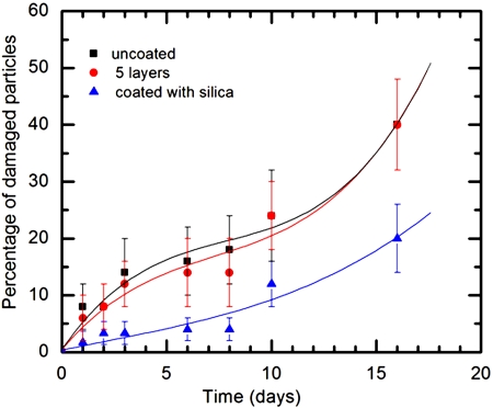
Mass transport of Rhodamine B from agarose gel particles is shown in Fig. 3. The results indicate that the presence of polyelectrolyte coating slows down the diffusion process. The corresponding diffusion coefficients were calculated by fitting the equation 1 to the experimental data. The diffusion coefficients of uncoated and coated particles are 6.821×10⁻¹¹ m2∕s and 3.820×10⁻¹¹ m2∕s, respectively. Mechanical stability of capsules is compared for the particles with and with out polymer coatings in Fig. 4. After 10 days, the percentage of ruptured particles for uncoated particles and 5-layer polyelectrolyte coated particles became almost the same. However, the percentage of ruptured particles with silica coating remained low. Results indicate that additional silica coating over polyelectrolyte coating enhanced the mechanical stability of the gel particles.
Figure 3.
Mass transfer of Rhodamine B in uncoated (▴) and 5-layer polyelectrolytes coated (∎) agarose gel particles. Lines are fit of equation 1 to calculate the diffusion coefficients.
Figure 4.
Comparison of mechanical stability for uncoated agarose particles (∎), 5-layer polyelectrolyte coating (●), and 5-layer polyelectrolyte plus 20-nm-silica coating (▴).
CONCLUSION
Using microfluidic devices, microcapsules with narrow size distribution were obtained. We demonstrated the capability to tailor transport and mechanical properties of semi-permeable membranes surrounding the biocompatible cell capsules using layer-by-layer polyelectrolyte coating and nano-silica particle coating. This method may help to develop an optimized environment for the cells to survive longer and maintain required functions such as secreting essential hormones. We are further testing the viability of living cells inside the capsules. By multilayer coating, we aim to tune the immune-isolation properties of the microcapsules.
References
- Lim F. and Sun A. M., Science 10.1126/science.6776628 210, 908 (1980). [DOI] [PubMed] [Google Scholar]
- Al-Hendy A., Hortelano G., Tannenbaum G. S, and Chang P. L, Hum. Gene Ther. 7, 61 (1996). [DOI] [PubMed] [Google Scholar]
- Chang P. L., Shen N., and Westcott A. J., Hum. Gene Ther. 4, 433 (1993). [DOI] [PubMed] [Google Scholar]
- Xu W., Liu L., and Charles I. G., FASEB J. 16, 213 (2002). [DOI] [PubMed] [Google Scholar]
- Chang T. M., Science 10.1126/science.146.3643.524 146, 524 (1964). [DOI] [PubMed] [Google Scholar]
- Orive G., Rosa M., Gascon A. R., Calafiore R., Chang T. M. S., De Vos P., Hortelano G., Hunkeler D., Lacik I., Shapiro A. M. J., and Pedraz J. L., Nat. Med. 9, 104 (2003). [DOI] [PubMed] [Google Scholar]
- Gin H., Dupuy B., Baquey C., Ducassou D., and Aubertin J., J. Microencapsul. 4, 239 (1987). [DOI] [PubMed] [Google Scholar]
- Aomatsu Y., Iwata H., Takagi T., Amemiya H., Nakajima Y., Kanehiro H., Hisanaga M., Fukuoka T., and Nakano H., Transplant. Proc. 24, 2922 (1992). [PubMed] [Google Scholar]
- Iwata H., Takagi T., and Amemiya H., Transplant. Proc. 24, 952 (1992). [PubMed] [Google Scholar]
- Iwata H., Takagi T., Iwata, Yamashita K., Kobayashi K., and Amemiya H., Transplant. Proc. 24, 997 (1992). [PubMed] [Google Scholar]
- Lim S. T., Martin G. P., Berry D. J., and Brown M. B., J. Controlled Release 66, 281 (2000). [DOI] [PubMed] [Google Scholar]
- Ribeiro A. J., Neufeld R. J., Arnaud P., and Chaumeil J. C., Int. J. Pharm. 187, 115 (1999). [DOI] [PubMed] [Google Scholar]
- Sakai S., Kawabata K., Ono T., Ijima H., and Kawakami K., Biotechnol. Bioeng. 10.1002/bit.20006 86, 168 (2004). [DOI] [PubMed] [Google Scholar]
- Sakai S., Kawabata K., Ono T., Ijima H., and Kawakami K., Biomaterials 26, 4786 (2005). [DOI] [PubMed] [Google Scholar]
- Meldrum D. R. and Holl M. R., Science 10.1126/science.297.5584.1197 297, 1197 (2002). [DOI] [PubMed] [Google Scholar]
- Workman V. L., Dunnett S. B., Kille P., and Palmer D. D., Biomicrofluidics 10.1063/1.2431860 1, 014105 (2007). [DOI] [PMC free article] [PubMed] [Google Scholar]
- Sugiura S., Oda T., Izumida Y., Aoyagi Y., Satake M., Ochiai A., Ohkohchi N., and Nakajima M., Biomaterials 26, 3327 (2005). [DOI] [PubMed] [Google Scholar]
- Anna S. L., Bontoux N., and Stone H. A., Appl. Phys. Lett. 10.1063/1.1537519 82, 364 (2003). [DOI] [Google Scholar]
- Xu Q. and Nakajima M., Appl. Phys. Lett. 10.1063/1.1812380 85, 3726 (2004). [DOI] [Google Scholar]
- Ward T., Faivre M., Abkarian M., and Stone H. A., Electrophoresis 10.1002/elps.200500173 26, 3716 (2005). [DOI] [PubMed] [Google Scholar]
- Colton C. K., Trends Biotechnol. 14, 158 (1996). [DOI] [PubMed] [Google Scholar]
- Hammond P. T., Adv. Math. 16, 1271 (2004). [Google Scholar]
- Xia Y. N. and Whitesides G. M., Angew. Chem., Int. Ed. 37, 550 (1998). [DOI] [PubMed] [Google Scholar]
- Crank J., The Mathematics of Diffusion (Clarendon Press, Oxford, 1975). [Google Scholar]


