Abstract
This paper reports the improvement of rectification effects in diffuser∕nozzle structures with viscoelastic fluids. Since rectification in a diffuser∕nozzle structure with Newtonian fluids is caused by inertial effects, micropumps based on this concept require a relatively high Reynolds numbers and high pumping frequencies. In applications with relatively low Reynolds numbers, anisotropic behavior can be achieved with viscoelastic effects. In our investigations, a solution of dilute polyethylene oxide was used as the viscoelastic fluid. A microfluidic device was fabricated in silicon using deep reactive ion etching. The microfluidic device consists of access ports for pressure measurement, and a series of ten diffuser∕nozzle structures. Measurements were carried out for diffuser∕nozzle structures with opening angles ranging from 15° to 60°. Flow visualization, pressure drop and diodicity of de-ionized water and the viscoelastic fluid were compared and discussed. The improvement of diodicity promises a simple pumping concept at low Reynolds numbers for lab-on-a-chip applications.
INTRODUCTION
After almost two decades of development, fluid delivery still remains as one of the most important topics of microfluidics. Although numerous research activities on micropumps has been reported in the past,1, 2 commercially available lab-on-a-chip systems still rely on external pumps for fluid delivery. The major hurdles for the integration of micropumps on a lab-on-a-chip platform is the complexity and the corresponding cost as well as the high failure rate. Moving parts such as valves and actuators are the main factors leading to the complexity and failure of micropumps. Different concepts of both passive and active microvalves were recently reviewed by Oh and Ahn.3
Valveless concepts such as pumping using flexural plate waves4, 5 and rectification structures are attractive for integration in lab-on-a-chip (LOC) platforms because of their simple fabrication and the absence of moving parts. The diffuser∕nozzle is a well-reported structure with rectification properties. The rectification effect was reported by Stemme and Stemme6 using a nozzle∕diffuser machined in brass. Gerlach and Wurmus7 reported the same effect with nozzle∕diffusers which are anisotropically etched in silicon. This rectification effect was later used in micropumps.8, 9 For a compact design, planar diffuser∕nozzle structures were etched in silicon.10 This planar diffuser∕nozzle structure was also implemented in micropumps.11, 12 Another interesting planar structure with rectification property is the Tesla valve.13 The Tesla valve is a microfluidic network with a side loop joining the main channel at a sharp angle. The rectification properties can be optimized by the radius of the loop and the join angle.14 The rectification effect in the above structures is caused by the anisotropy of pressure drop across these structures. For Newtonian fluids, this anisotropy relies on the inertial effects and thus can only function effectively at relatively high Reynolds numbers. Detailed investigations of the effect of opening angle on the rectification behavior were recently reported by Sun and Yang.15
Recently, Groisman et al.16 reported the use of non-Newtonian viscoelastic fluids for realizing microfluidic memory and control devices. The anisotropy of pressure drop versus flow rate was reported in more detail later by the same author.17 Groisman et al. used an aqueous solution of 0.01 wt.% of polyacrylamide, sucrose, NaCl, and surfactant Tween 20. The test device was fabricated in polydimethylsiloxane (PDMS). Only one type of diffuser∕nozzle structure with an opening angle of approximately 60° was investigated. In this paper, we investigate another type of viscoelastic fluid which consists only of 0.1 wt.% poly(ethylene-oxide) (PEO) diluted in water. Furthermore, the effect of the opening angles are also investigated. The microfluidic devices were fabricated in silicon and glass. These hard device materials minimize the possible nonlinear effects caused by soft material such as the elastomer PDMS used in Ref. 17. While the diffuser∕nozzle structure reported in Ref. 17 was rather arbitrary, we investigate in this paper the influence of the opening angle of the diffuser∕nozzle structure on the rectification property. A set of devices with opening angles of 15°, 30°, 45°, and 60° were characterized and compared. Results from this investigation show the potential of utilizing viscoelastic fluids with optimized diffuser∕nozzle structures for simple and efficient pumping in LOC platforms.
DEVICES AND MATERIALS
Fabrication of test devices
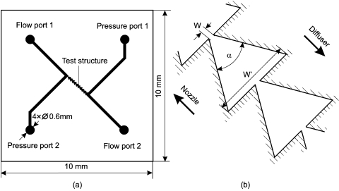
Figure 1a depicts the layout of the test device. Two of the four 0.6-mm-diameter access holes are used as the inlet and the outlet for the fluid, while the other two are access ports for pressure measurement. The pressure ports are placed close to the test section, which consists of ten diffuser∕nozzle structures connected in serial. Thus, errors by pressure loses can be minimized. The test devices have a standard size of 1×1 cm2. All the test devices can therefore share the same casing for micro∕macrointerfacing. Figure 1b depicts the detailed geometry of the diffuser∕nozzle structure. Due to their rectification (diodelike) behavior, a pair of these structures together with a pump chamber would allow pumping in the rectified direction.
Figure 1.
Layout of the test device: (a) Chip layout, (b) the diffuser∕nozzle structure.
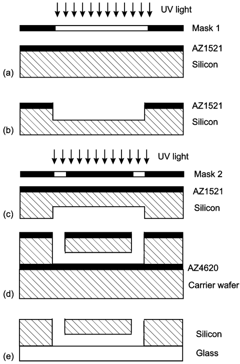
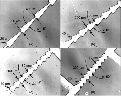
Figure 2 describes schematically the fabrication steps of the test devices. To start with, a double-sided polished wafer was spin coated with a 1.6-μm-thick photo resist (AZ1521). The photo resist layer was then exposed and developed with the first mask with the channel structures, Fig. 2a. The channel structures were subsequently etched 50 μm into the silicon substrate using deep reactive ion etching (DRIE), Fig. 2b. The etched depth was measured with a profiler before stripping the photo resist layer. After stripping the AZ1521 layer on the front surface, a second AZ1521 layer was spin coated and exposed using a second mask with the access holes, Fig. 2c. A carrier wafer was spin coated with a thin layer of the photo resist AZ4620 for temporary bonding of the front surface to the carrier wafer. Subsequently, the back surface was etched until the access holes met the channel structures on the front surface, Fig. 2d. The resist on the back surface and the carrier wafer were then released in an acetone bath. Subsequently, the silicon wafer was anodically bonded to a glass wafer, Fig. 2e. Finally, the wafer was diced into single 1×1 cm2 test devices. Figure 3 shows the fabricated channel structures with their dimensions. In contrast to the designs reported in Ref. 17, the sharp corners in our diffuser∕nozzle structures are rounded with a radius of 20 μm for the 15° device and 40 μm for other devices to encourage flow separation and recirculation. The length of the test section with the 10 diffuser∕nozzle structures decreases from the 15° device to the 60° device.
Figure 2.
Fabrication steps of the silicon∕glass chip: (a) Lithography of the channel structures (first mask), (b) DRIE of the channel structures, (c) lithography of the access holes (second mask), (d) DRIE of the access holes, and (e) anodic bonding of the glass cover.
Figure 3.
The fabricated devices with different opening angles α and their structure dimensions: (a) α=15°, (b) α=30°, α=45°, α=60°.
Preparation of the viscoelastic fluid
For a given geometry, the elastic effects of a viscoelastic fluid flow can be characterized by the Deborah number De, which is the ratio between the characteristic relaxation time and the characteristic time of the flow.18 The Deborah number De can be determined by the characteristic shear rate and relaxation time as
| (1) |
where the characteristic shear rate is
| (2) |
and λ is the relaxation time of the viscoelastic fluid measured in seconds, is the average flow velocity, H=50 μm is the channel height, W is taken at the narrowest place of a structure, e.g., W=40 μm for 15° and W=80 μm for other angles, and is the volumetric flow rate. In the following experiments, the Reynolds number is defined as
| (3) |
At the microscale, the shorter characteristic time of the flow results in a higher Deborah number, and thus dominant elastic effect. The ratio between fluid elasticity to fluid inertia is called the elasticity number. From Eqs. 1, 3, the elasticity number can be determined as
| (4) |
The viscoelastic fluid employed in our experiment consists of 0.1 wt.% polyethylene oxide (PEO) in de-ionized (DI) water. The mean molecular weight (Mw) of PEO (The Dow Chemical Co.) is approximately 2×10⁶ g∕mol. For flow visualization, the solution of dispersed 3-m red fluorescent microsphere (6.7×10¹¹ particles∕mL, Duke Scientific Co.) was added to the fluid at a volume ratio of 0.1:1. The fluorescent particles have excitation and emission wavelengths of 540 nm and 610 nm, respectively.
The relaxation time of the 0.1 wt.% solution was reported by Rodd et al.18 as λ=1.5×10⁻³ s. The zero-shear viscosity of 0.1% PW was determined by a viscometer (Contraves LS 40) as μ0=2.24×10⁻³ Pa s. The density of the fluid was determined as ρ=997 kg∕m3.19 According to Eq. 4 and for the given geometries W=200 μm, H=50 μm, the elasticity number in our experiment is El=1690 in the case of 15° structure and El=611 in the case of other opening angles. The very large elasticity numbers indicate that elastic force will be dominant in our test devices. The density and dynamic viscosity of DI water are taken as ρW=997 kg∕m, μW=1.17×10⁻³ Pa s, respectively.
In general, rectification in a diffuser∕nozzle structure with Newtonian fluids is caused by inertial effects at higher Reynolds numbers. Due to the small channel geometry, a relatively large flow rate is required to achieve inertia dominated effects. At the same time, the small geometry leads to a larger Deborah number, where elastic behavior of non-Newtonian fluids becomes dominant. As mentioned above, the relative dominance of elastic to inertial effects is characterized by the elasticity number (El=De∕Re). In our experiments, the elasticity number on the order of 1000 indicate a strong elastic effect, which will significantly affect the rectification behavior of the diffuser∕nozzle structure.
Experimental setup and procedures
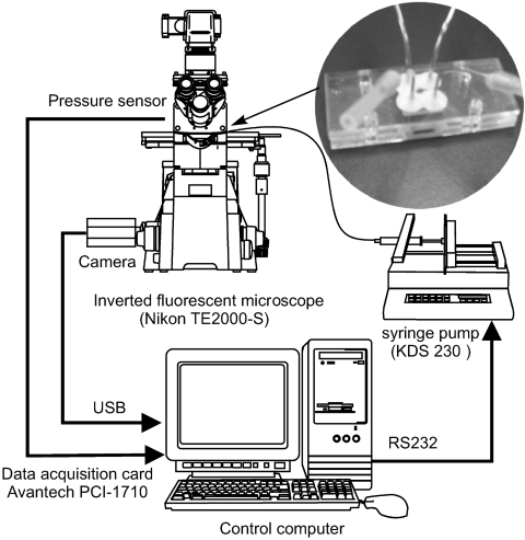
Figure 4 depicts the setup used in our experiments. The main components for fluid delivery and automatic recording of the pressure drop as a function of flow rates are a programmable syringe pump, a pressure sensor and a data acquisition card. A personal computer (PC) controls all the components and records the data accordingly. The syringe pump (KDS230, KD Scientific Inc., USA) is programmable from the PC using the serial RS232 protocol. The pressure sensor (HCX001, Sensottechnics, Germany) has a range from 0 to 1 bar corresponding to an output signal from 0.5–4.5 V. The output signal of the pressure sensor is connected to a 12-bit data acquisition card (PCI-1710, Advantech, Taiwan) which is plugged in a peripheral component interface (PCI) slot of the PC. A customized program was written in MATLAB to control the syringe pump over the serial port COM1 and to record the output signal from the pressure sensor. The program first adjusts the flow rate through the syringe pump. Subsequently, a number of sensor values were recorded over a predefined time. The average voltage value was then calculated and converted into pressure. At the same time, the program can monitor and capture images from the camera. The silicon∕glass chip was connected to external tubing by a customized casing made in PMMA. The completed test device with casing is shown as an inset in Fig. 4.
Figure 4.
Experimental setup for automatic recording of the pressure drop as a function of flow rate.
Flow visualization was carried out with an image acquisition system as depicted in Fig. 4. The optical system consisted of an inverted microscope (Model ECLISPE TE2000-S) with a set of epifluorescent attachments (Nikon G-2E∕C, excitation filter for 540 nm, dichroic mirror for 565 nm and an emission filter for 605 nm) that suits the excitation and emission wavelengths of the tracing particles. A commercial digital camcorder (Sony, DCR-DVD803E) was used to capture the flow visualized by the fluorescent particles. The images can be stored on a DVD on the camcorder or transferred directly to the computer over a universal serial bus (USB) interface.
RESULTS AND DISCUSSIONS
Flow visualization
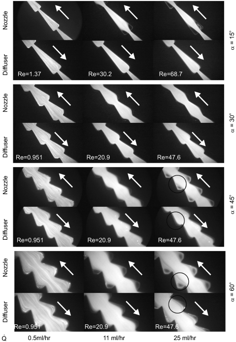
Figure 5 shows the flow of DI water in the different channel structures visualized with the fluorescent microparticles. In the test device with 15° opening angle and in the nozzle direction, visible recirculations can be observed at high Reynolds numbers (Re>10). This behavior is typical for Newtonian fluids flowing through a sudden expansion. Flows in the diffuser direction do not show this behavior. However, flow separation in the diffuser direction can be observed at larger opening angles of 45° and 60°. The existence of flow separation and recirculation in both directions decreases their difference in pressure drops.
Figure 5.
Streak images of DI-water flow in diffuser∕nozzle structures with different angles (separation and recirculation are indicated by circles).
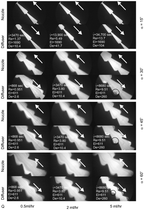
Figure 6 shows the flow of PEO 0.1 wt.% solution in the same devices used for the previous experiments with DI water. Due to the higher viscosity and the limited range of the pressure sensor, measurements can only be carried out at lower flow rates and Reynolds number as compared to DI water. At the relatively low Reynolds number shown in Fig. 6, no flow separation and recirculation due to inertial effects can be observed in the nozzle direction. However, Fig. 6 shows recirculation at the sudden constriction at higher flow rates. These vortices grow with increasing flow rate and are a clear indication of the viscoelastic effect. These recirculations do not exist in the nozzle direction. Furthermore, the size of the vortices relative to the size of the diffuser∕nozzle structure increases with increasing angles. Thus, a significant rectification is expected if viscoelastic fluids are employed in the test devices. This viscoelastic effect becomes more significant at higher opening angles.
Figure 6.
Streak images of PEO 0.1 wt.% flow in diffuser∕nozzle structures with different angles (separation and recirculation are indicated by circles).
Pressure measurement
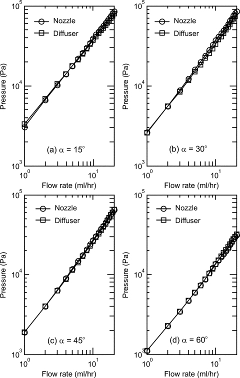
As mentioned in the previous section, the pressure drop across the diffuser∕nozzle structures was measured automatically by a customized program that controls the syringe pumps and records the sensor output. Due to the different viscosities and the limited range of the pressure sensor, DI water and the PEO 0.1 wt.% solution were characterized with flow rate ranges of 0 to 20 ml∕h and 0 to 5 ml∕h, respectively. Figure 7 shows the measured results of DI water in the four different diffuser∕nozzle devices. The straight slope indicates the Newtonian behavior of the liquid. At the same flow rate, the pressure drop in the nozzle direction is slightly higher than that in the diffuser direction. Thus a small rectification effect can be expected for DI water.
Figure 7.
Pressure drop versus flow rate curves of water in forward and backward directions: (a) α=15°; (b) α=30°; (c) α=45°; (d) α=60°.
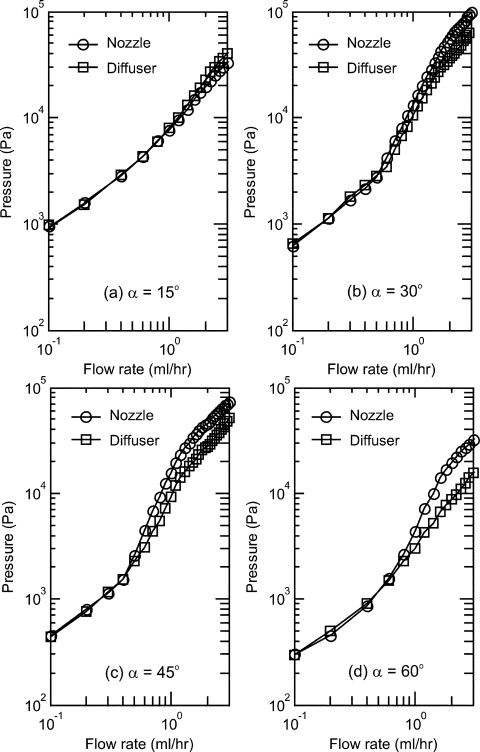
Figure 8 shows the measured results of the PEO 0.1 wt.% solution. In contrast to the curves of DI water, the results show a clear non-Newtonian behavior. The curves of diffuser and nozzle directions separate at a relatively low flow rate of 0.7 ml∕h indicating a strong rectification behavior. The results depicted in Fig. 8 clearly show that for the same flow rate the pressure difference between the nozzle direction and the diffuser direction increases with the opening angle α.
Figure 8.
Pressure drop versus flow rate curves of PEO 0.1 wt.% solution in forward and backward directions: (a) α=15°; (b) α=30°; (c) α=45°; (d) α=60°.
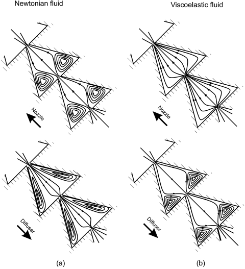
Figure 9 shows the representative flow patterns of DI water and the PEO 0.1 wt.% solution as observed in Figs. 78. At high Reynolds number, flow separation and recirculation due to inertia occur in both directions of a the Newtonian flow. Thus, the difference between pressure losses in both directions are minimum for a Newtonian flow. At lower Reynolds numbers, recirculation only occurs in diffuser direction of the viscoelastic flow, due to the dominant elastic effect. The contrasting difference in flow patterns leads to a large difference in pressure losses. Therefore in the same diffuser∕nozzle structure, a viscoelastic fluid will lead to a stronger rectification effect compared to a Newtonian fluid.
Figure 9.
Representative flow patterns in the diffuser∕nozzle structure of (a) a Newtonian fluid and (b) a viscoelastic fluid.
To quantify the rectification effect of the tested structures, the concept of diodicity was used. The relation between the pressure drop and the average flow velocity may be written as
| (5) |
and the pressure loss coefficient can be determined for each average flow velocity as
| (6) |
The ratio between the loss coefficients of nozzle direction and diffuser direction is called the diodicity20
| (7) |
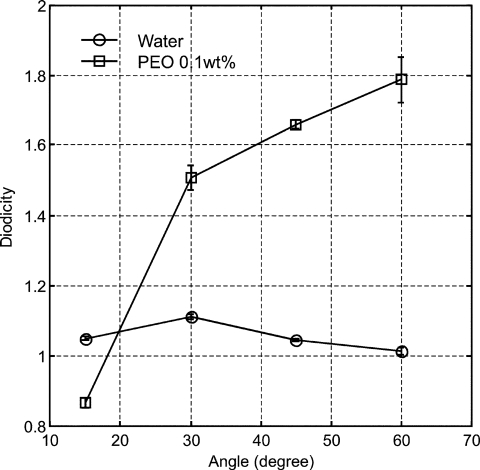
Figure 10 shows the diodicities as a function of the opening angle α. Since the diodicity is also a function of flow rate or Reynolds number and is approximately constant only at higher Reynolds numbers. For DI-water, the diodicity at 11 ml∕h was selected. Even at this relatively high Reynolds number, the diodicity is small. A maximum diodicity at α=30° can be observed. If the diffuser∕nozzle structure is used as the flow rectifier in a micropump, the diffuser direction is the pumping direction. The diodicity of PEO 0.1 wt.% solution was taken at 2 ml∕h. Even at this low Reynolds numbers (5.49 for 15° and 3.8 for others), a large diodicity was achieved. It is interesting to note that at α=15° the diodicity is less than 1, indicating pumping in the nozzle direction if the structure is used in a micropump. This diodicity can be explained by interplay between inertial and elastic effects (Fig. 6). The magnitude of inertial effects scales with the square of the Reynolds number. Although the elasticity number is higher in this case compared to other opening angles, the Reynolds number is also higher leading to the different rectification behavior at α=15°. Further understanding on the balance between elastic, inertial, and viscous forces in a structure with small opening angle can be achieved by a detailed numerical simulation.
Figure 10.
Diodicity for DI-water and PEO 0.1 wt.% solution as function of the diffuser angle.
CONCLUSIONS
We have presented the clear improvement of rectification effects in diffuser∕nozzle structures using viscoelastic fluids. An array of 10 diffuser∕nozzle structures were fabricated in silicon and glass. The structures have different opening angles. The devices were tested with water as a Newtonian fluid and a dilute solution of PEO as a non-Newtonian fluid. Flow separation and recirculation due to inertial effects were observed with the DI water at relatively high flow rates and Reynolds numbers above 10. The dilute PEO solution, however, shows recirculation at a sudden constriction at a relatively low Reynolds number of about 1. The recirculation was caused by the viscoelastic behavior of the fluid. The results indicate that the rectification effect in a diffuser∕nozzle structure can exist at rather low Reynolds number. The behavior observed with flow visualization was confirmed with the measurements of the pressure drop. The dilute PEO solution shows a clear improvement in diodicity as compared to DI water. The diodicity of the PEO solution is about two times that of DI water, even with one order of magnitude lower Reynolds number. The results show the potential of employing viscoelastic fluids in diffuser∕nozzle micropumps. The pumping performances can be improved significantly by adding a small amount of long-chain polymer such as PEO that transform an aqueous working solution into a viscoelastic fluid.
ACKNOWLEDGMENTS
N. T. Nguyen and Y. C. Lam would like to thank the Ministry of Education, Singapore for its financial support under project RG22∕05, “Characterisation of Low Viscosity Elastic Fluids in Microscale.”
References
- Nguyen N. T., Huang X. Y., and Chuan T. K. ASME J. Fluids Eng. 10.1115/1.1459075 124, 384 (2002). [DOI] [Google Scholar]
- Laser D. J. and Santiago J. G. J., J. Micromech. Microeng. 14, R35 (2004). [DOI] [Google Scholar]
- Oh K. W. and Ahn C. H., J. Micromech. Microeng. 16, R13 (2006). 10.1088/0960-1317/16/5/R01 [DOI] [Google Scholar]
- Nguyen N. T., Meng A. H., Black J., and White R. M., Sens. Actuators, A 10.1016/S0924-4247(99)00279-4 79, 115 (2000). [DOI] [Google Scholar]
- Nguyen N. T. and White R. M., IEEE Trans. Ultrason. Ferroelectr. Freq. Control 10.1109/58.883536 47, 1463 (2000). [DOI] [PubMed] [Google Scholar]
- Stemme E. and Stemme G., Sens. Actuators, A 10.1016/0924-4247(93)80213-Z 39, 159 (1993). [DOI] [Google Scholar]
- Gerlach T. and Wurmus H., Sens. Actuators, A 10.1016/0924-4247(96)80097-5 50, 135 (1995). [DOI] [Google Scholar]
- Nguyen N. T. and Huang X. Y., Sens. Actuators, A 10.1016/S0924-4247(00)00500-8 88, 104 (2001). [DOI] [Google Scholar]
- Jeong O. C. and Yang S. S., Sens. Actuators, A 10.1016/S0924-4247(99)00392-1 83, 249 (2000). [DOI] [Google Scholar]
- Olsson A., Stemme G., and Stemme E., Sens. Actuators, A 10.1016/S0924-4247(97)80104-5 57, 137 (1996). [DOI] [Google Scholar]
- Olsson A., Stemme G., and Stemme E., Sens. Actuators, A 10.1016/S0924-4247(99)00320-9 84, 165 (2000). [DOI] [Google Scholar]
- Heschel M., Mullenborn M., and Bouwstra S., J. Microelectromech. Syst. 10.1109/84.557529 6, 41 (1997). [DOI] [Google Scholar]
- Forster F. K., Bardell R. L., Afromowitz M. A., Sharma N. R., and Blanchard A., Proceedings of ASME Fluids Engineering Division, ASME International Mechanical Engineering Congress and Exposition, San Francisco (ASME, New York, 1995), Vol. 234, p. 39. [Google Scholar]
- Truong T. Q. and Nguyen N. T., in Technical Proceedings of the 2003 Nanotechnology Conference and Trade Show, San Francisco (NIST, Cambridge, MA, 2003), Chap. 9, p. 178. [Google Scholar]
- Sun C. L. and Yang Z. H., J. Microelectromech. Syst. 17, 2031 (2007). [DOI] [Google Scholar]
- Groisman A., Enzelberger M., and Quake S., Science 10.1126/science.1083694 300, 955 (2003). [DOI] [PubMed] [Google Scholar]
- Groisman A. and Quake S., Phys. Rev. Lett. 10.1103/PhysRevLett.92.094501 92, 094501 (2004). [DOI] [PubMed] [Google Scholar]
- Rodd L. E., Scott T. P., Boger D. V., Cooper-White J. J., and McKinley J. H., J. Non-Newtonian Fluid Mech. 10.1016/j.jnnfm.2005.04.006 129, 1 (2005). [DOI] [Google Scholar]
- Gan H. Y., Lam Y. C., Nguyen N. T., Tam K. C., and Yang C., Microfluidics and Nanofluidics 3, 10.1007/s10404-006-0109-4 101 (2006). [DOI] [Google Scholar]
- Nguyen N. T., Fundamentals and Applications of Microfluidics, 2nd ed. (Artech House, Boston, 2006). [Google Scholar]


