Abstract
With the increasing popularity of actuators involving smart materials like piezoelectric, control of such materials becomes important. The existence of the inherent hysteretic behavior hinders the tracking accuracy of the actuators. To make matters worse, the hysteretic behavior changes with rate. One of the suggested ways is to have a feedforward controller to linearize the relationship between the input and output. Thus, the hysteretic behavior of the actuator must first be modeled by sensing the relationship between the input voltage and output displacement. Unfortunately, the hysteretic behavior is dependent on individual actuator and also environmental conditions like temperature. It is troublesome and costly to model the hysteresis regularly. In addition, the hysteretic behavior of the actuators also changes with age. Most literature model the actuator using a cascade of rate-independent hysteresis operators and a dynamical system. However, the inertial dynamics of the structure is not the only contributing factor. A complete model will be complex. Thus, based on the studies done on the phenomenological hysteretic behavior with rate, this paper proposes an adaptive rate-dependent feedforward controller with Prandtl-Ishlinskii (PI) hysteresis operators for piezoelectric actuators. This adaptive controller is achieved by adapting the coefficients to manipulate the weights of the play operators. Actual experiments are conducted to demonstrate the effectiveness of the adaptive controller. The main contribution of this paper is its ability to perform tracking control of non-periodic motion and is illustrated with the tracking control ability of a couple of different non-periodic waveforms which were created by passing random numbers through a low pass filter with a cutoff frequency of 20Hz.
Keywords: Hysteresis, piezoelectric actuator, control
1 Introduction
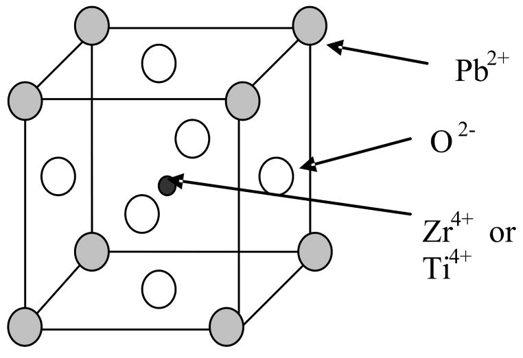
Hysteresis is a common phenomenon in applications involving issues like magnetic fields and smart materials. One common example of smart materials is piezoelectric actuators. Piezoelectric actuators are playing an ever increasing role in positioning technology. Dong et al. [1] drove their precision compliant parallel positioner using piezoelectric actuators. Other applications include cell manipulation, scanning tunneling microscopy and diamond turning machines. One common example of piezoelectric ceramic is PZT ceramic. PZT is a solid solution of PbZrO3 and PbTiO3 and the general formula is Pb(ZryTi1−y)O3. PZT has the pervoskite ABO3 structure (Fig. 1).
Fig. 1.
A Crystal Unit Cell of PZT Ceramic
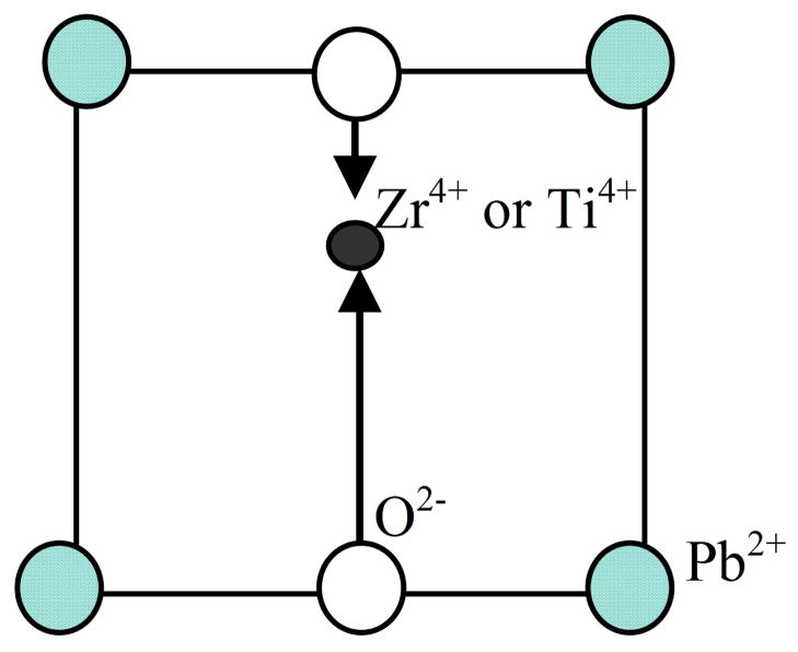
When a voltage is applied across the ceramic, the atom at the center (Zr or Ti) will displace (Fig. 2). A pole is induced and the net polarization in the PZT ceramic changes. This results in the deformation of the material. The usage of deformation as actuators is a solution for precise actuation as no mechanical backlash is involved. A reverse observation will occur when the ceramic is loaded. This is why piezoelectric materials are able to function as both actuators and sensors. However, due to the nature of polarization, such materials exhibits non-linear multi-path hysteresis that makes control challenging, especially if precise tracking is required.
Fig. 2.
Polarization of a PZT Ceramic
Mathematical hysteresis models are commonly mathematically defined as rate-independent as velocity is not one of the inputs. However, the phenomenological hysteretic behavior of most smart materials changes with rate. In most literature, a smart material actuator is commonly modeled using a cascade of rate-independent hysteresis operator and a dynamical system. However, the inertial dynamics of the structure is not the only contributing factor on the overall rate-dependent behavior. As mentioned in Landauer et al. [2] and Smith et al. [3], the nature of the polarization is dependent on rate too. As the rate-dependent portion of the model was not completely accounted, most of the signals used in most of the papers are periodic signals. As a complete model will be quite complex, a phenomenological rate-dependent hysteresis model is proposed in this paper.
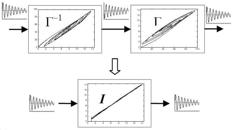
There are a few proposed methods of controllers to control piezoelectric actuators. One popular method is the usage of a phenomena inverse feedforward controller. As the studies on the hysteretic behavior of such materials are not that well studied at the atom level yet, phenomenological modeling of the hysteretic behavior is commonly used. The inverse model is then used as a feedforward controller to predict and linearize the relationship between the input and output (Fig. 3). Song et al. [4] proposed using a feedforward model in their controller to improve the performance of the control system. Choi et al. [5] also demonstrated that the performance of their PID controller was improved with a feedback linearization loop.
Fig. 3.
Linerization of Hysteretic Plant using Inverse Feedforward Controller
There are several mathematical models to model the phenomenological hysteretic behavior. Among the simplest way is to utilize two polynomials. Two sets of polynomial are used to model the forward and backward paths. This method will not work when the turning point is changed as it is not continuous. Sun et al. [6] proposed a new mathematical model by modifying the polynomials and Ru and Sun [7] further improved the controller with creep compensation.
Among other mathematical hysteresis models, Preisach model [8–11] is the more commonly used model. Maxwell slip model [12] and hysteron model [13] are some other options available.
Prandtl-Ishlinskii (PI) hysteresis model is used in this paper. A major advantage of PI operators is the availability of an analytical inverse model. This is ideal for real-time situation. The inverse model is then used as the feedforward controller to linearize the hysteretic behavior.
The hysteretic behavior of the piezoelectric actuators changes with environmental conditions like temperature. It is troublesome to regularly model each actuator before usage. In addition, the hysteretic behavior of these actuators change as the actuators age. A couple of adaptive controllers have been proposed [10,13–16]. Zhao and Tan [15] proposed using neural network to update the parameters of the Preisach based model while Liaw et al. proposed using sliding mode control. However, the input signals to most of the present papers are mainly limited to periodic signals. These controllers are unable to perform that well for non-periodic input motion because the rate-dependent portion of the piezoelectric actuators is difficult to be modeled fully.
Thus, this paper proposed an adaptive rate-dependent hysteresis feedforward controller for piezoelectric actuators. The adaptive controller will account for the dynamic environmental conditions. In addition, this adaptive controller introduces no phase difference and is suitable for tracking purpose.
A brief introduction of the rate-dependent phenomenological Prandtl-Ishlinskii hysteresis model is given in the following section. A description of the adaptive controller is given in section III, followed by an analysis of the controller, experimental results, discussions and conclusion.
2 Hysteresis Mathematical Model
This section briefly describes the rate-dependent Prandtl-Ishlinskii hysteresis model. Supplementary details of the Prandtl-Ishlinskii hysteresis operators can be found in Kuhnen et al. [17–20] and Ang et al. [21]
2.1 Prandtl-Ishlinskii (PI) Play Operator
The play operator in the PI hysteresis model, commonly used to model the backlash between gears, is defined by:
| (1) |
where x is the control input, y is the actuator response, r is the control input threshold value or the magnitude of the backlash, and T is the sampling period.
Initial Condition of (1) is given by:
| (2) |
where y0 is a real number which is usually initialized to 0. To change the gradient, a weight value wh is multiplied to the PI operator Hr. By summing a number of such operators with different threshold values and weights, a hysteresis model is obtained:
| (3) |
where weight vector and H⃗r[x(t), y⃗0] = [Hr0 [x(t), y00] … H⃗rn [x(t), y0n]]T with the threshold vector r⃗ = [r0 …rn]T where rn > … > r0, r0 = 0, and the initial state vector y⃗0 = [y00 … y0n]T.
Unlike the Preisach model, which behaves like a flight of stairs, the PI operator is a better mathematical model as it is a first order gradient and it is also more mathematically simpler. To account for the one sided characteristics of piezoelectric actuators, Ang et al. [21] proposed setting the value of rn to be half of the maximum control input.
2.2 Modified Prandtl-Ishlinskii
The nature of PI operator is symmetrical about the center point of the loop, but this is not really true in the phenomena observation. To overcome this restriction, Ang et al. [21] and Kuhnen et al. [17] proposed using a one-sided dead zone operator:
| (4) |
| (5) |
where weight vector , S⃗d[y(t)] = [Sd0[y(t)] … Sdm[y(t)]]T, d is the threshold value in the dead-zone operator and z is the actuator’s displacement response. The general idea of the one-sided dead zone operators is to bend the graph and make it not symmetrical. In this paper, the weights of the dead zone operator are kept as a constant and will not change in the adapting mechanism. The value of w⃗s is obtained by actuating the piezoelectric actuator with a periodic waveform and then performing least square minimization of the error function (6). A sinusoidal waveform of 8Hz was used for this paper. The threshold values chosen for this paper were d⃗ = [0 12 20]. The values of w⃗s of a particular actuator need not be changed for different waveforms, but different actuators might require different values.
2.3 Parameter Identification
A phenomenological approach is like memorizing the path. Experimental values must be obtained in order to obtain the hysteresis model. After obtaining the experimental data, least square minimization of the error is performed to the weights w⃗h and w⃗s via
| (6) |
where and are the inverse parameters of and respectively and H⃗r′ and S⃗d′ are the H⃗r and S⃗d operators with the inverse parameters of r⃗ and d⃗ as the input respectively. The inverse parameters can be obtained by (10). This error function, obtained from Kuhnen et al. [17], is recommended over position error because the error will be linearly dependent on the weights.
2.4 Rate-Dependent Phenomenological Model
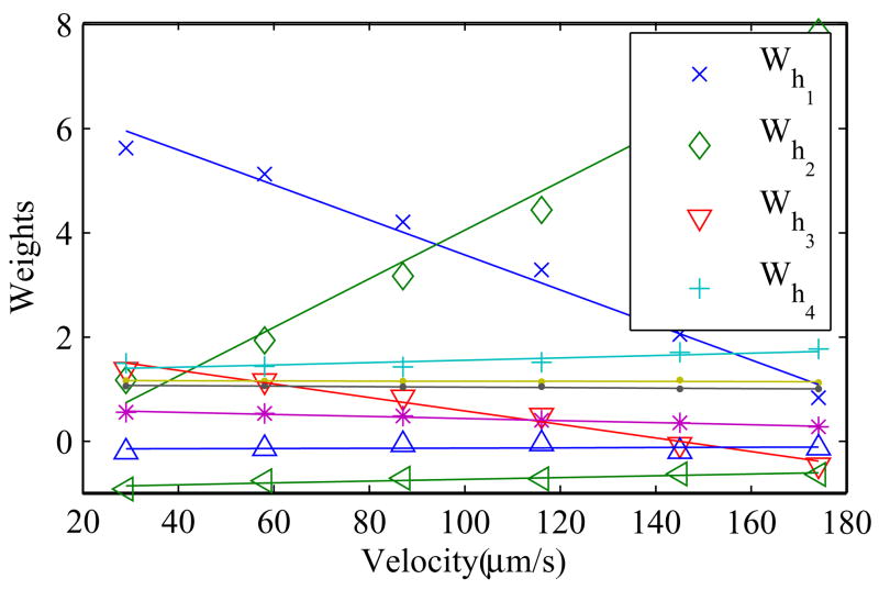
The phenomena response of the piezoelectric actuator is dependent on the velocity. Thus, experiments are carried out on piezoelectric actuators to obtain a rate-dependent phenomenological model. The actuator is actuated to achieve a desired triangular (to have constant speed) wave using an adaptive feedforward controller similar to [20]. Upon convergence, the converged weights are recorded. The gradient of the triangular wave is then varied and the corresponding weights are recorded. The hysteresis weights of the play operators are plotted against the control desired velocity rate. Experiments are carried out and the result is plotted in Fig. 4. Up to a certain velocity (this limit depends on the length of the piezoelectric ceramic), weights of the play operators of the piezoelectric actuator can be model linearly to the velocity input with good approximation.
Fig. 4.
Weights of the hysteresis play operators against velocity obtained from piezoelectric actuator P885.50 from Physik Instrumente
Thus, base on the phenomenological hysteretic behavior with rate, the equation to approximately relate the weights with rate is presented as follows:
| (7) |
where zd(t) is the desired displacement, bi is the slope of the best-fit line through the ai’s and the referenced slope ai is the intercept of the best-fit line. It is also interesting for the readers to note that the gradient of rate dependent relationship equation (7) is only significant for the first few weights as shown in Fig. 4.
Thus, the rate-dependent PI model becomes:
| (8) |
2.5 Inverse Model
The inverse PI model is commonly expressed using the stop operators. Kuhnen [17] showed that the inverse PI model can be expressed by PI play operators too. Thus, the inverse of the rate-dependent PI model can also be expressed as:
| (9) |
The inverse of the hysteresis model is basically a reflection along the 45° line. The inverse model parameters can be calculated by:
| (10) |
Thus, given the desired displacement, the required voltage can be obtained via:
| (11) |
| (12) |
where yd(t) is the desired displacement after passing through the inverse saturation operator and x(t) is the estimated required voltage.
3 Adaptive Feedforward Controller
The adaptive feedforward controller is described in this section. The adaptive feedforward controller is first given. The adapting mechanism, which is recursive least square, is next implemented with a slight modification. This section ends with an algorithm of the adapting mechanism for ease in implementation.
3.1 Adaptive Inverse Hysteretic Controller
A complete model is very complex. Thus, a phenomenological model of the actuator within the specification of the project’s requirement was used. Experiments on the actuators were performed according to the application’s specification and based on the phenomenological hysteretic behavior of the actuator, it seems that equation (13) is able to model the hysteretic actuator well when within the specification. Hence, an assumption that the hysteretic behavior of a piezoelectric actuator can modeled using (13) is made.
Given the input voltage, the actual output displacement from the hysteretic actuator is modelled to be:
| (13) |
where za(t) is the actual displacement, are the actual weights of the play operators. The actual displacement of the actuator is also the measured displacement. Equation (13) can also be rewritten as:
| (14) |
where a⃗p and b⃗p are the vectors of the vertical-axis intercept and gradient of the plant’s best fit lines that is described in Fig 4.
The error of the model is obtained as:
| (15) |
In this paper, to adapt the vectors a⃗ and b⃗, least square is performed with the cost function:
| (16) |
Assuming the hysteretic behavior of a piezoelectric actuator can be modeled accurately using equation (8), the vectors a⃗ and b⃗ will adapt as close to the behavior of the plant as possible. In other words,
| (17) |
| (18) |
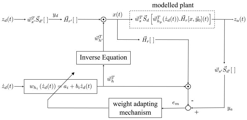
if the input signals satisfy the persistent excitation condition. With the adapted vectors a⃗ and b⃗ that can closely model the plant, can be obtained. Thus, the inverse can also be obtained using equation (10) and the desired-actual error will be minimized. The signal flow diagram of the adaptive feed-forward controller is given in Fig. 5.
Fig. 5.
Signal Flow Diagram of the Adaptive Feedforward Controller
3.2 Adaptive Weight-Control Mechanism
The input vector to the recursive least square (RLS) is:
| (19) |
where is Hri is Hri [x(t), y0]. It is more important to adapt the ai values to the hysteretic behavior than bi. It can also be seen in Fig. 4 that the gradient of the first few weights are more significant. Thus, the terms in the input vector,, is multiplied with the terms in a priority vector, [ca0, cb0,…, can, cbn]T, to obtain:
| (20) |
In this paper, cai is set to 1 and cbi is set to 0.007 if the unit of ż(t) is in μm/s.
The weight vector to be adapted is defined as:
| (21) |
The remaining derivation steps to obtain the algorithm are very similar to the derivation of adaptive filters using RLS and can be found in books like [22]. Other available adaptive laws found in adaptive control textbooks may be implemented, with some modification if needed.
3.3 Algorithm
Initialization of the weights is first performed as shown in (22). Note that the first weight must again be set to be a positive non-zero number. The matrix P is also initialized. After that, for each sample loop, the parameters are computed as described in (23).
Initialization:
| (22) |
where δ is a positive real number called the regularization parameter and is set to be a small positive constant for high signal to noise ratio (SNR) and set to be a large positive constant for low SNR.
For each instant of time, n = 1, 2, …, use
| (23) |
where λ is the forgetting factor which is a positive constant close to, but less than 1. When λ is set to 1, it implies infinite memory. Thus, set λ to be near unity if you want a controller that will remember most of the historical result, but it means it will adapt slower to a changing plant.
4 Simulation Results
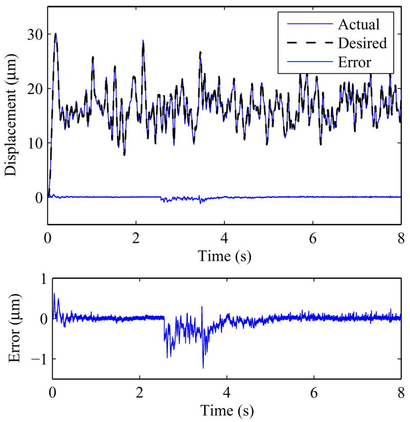
In this section, simulation is performed using the proposed adaptive controller. The weights of the a real piezoelectric actuator is first obtained through experiments. A few randomly created waves are then sent into the controller through simulation. The first portion shows the performance for a hysteretic plant that does not change while the second portion introduced a sudden change in the hysteretic plant at time 2.5sec to show its ability to adapt to changes. A number of simulation with different random input waves are performed for both portions. White noise with the amplitude of the interferometer’s noise is also introduced in all the simulations to make it more similar to real cases.
In adaptive related papers, mathematical analysis should be conducted. However, due to the operators in PI mathematical models, it is mathematically quite difficult to prove the convergence of the proposed adaptive controller using means like Lyapunov equations. Thus, a number of simulations with bounded input and bounded weights of the play operators is performed to the controller to test converence of the controller before real implementation.
4.1 Stationary Hysteretic Plant
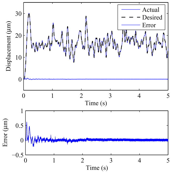
In the first simulation test, the rate-dependent hysteretic behavior of the actuator is kept constant. In other words, the plant/actuator is consistent. In order to make the simulation nearer to real life applications, a piezoelectric actuator is modeled and the parameters are obtained. Assuming that the parameters are not known, the weights are initialized as (22). Fig. 6 shows the simulation result of the controller.
Fig. 6.
Simulation result of a stationary rate-dependent plant
4.2 Robustness: Sudden Change in Hysteretic Plant
In the second simulation test, the controllers are subjected to a sudden change in the hysteretic behavior at time 2.5 sec to test its robustness. Fig. 7 shows the result. As seen in the figure, the controller is able to adapt to changes in the plant.
Fig. 7.
Simulation result of a rate-dependent plant with a sudden change in its parameters
4.3 Bounded input convergence test
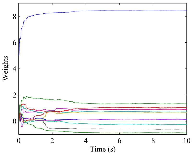
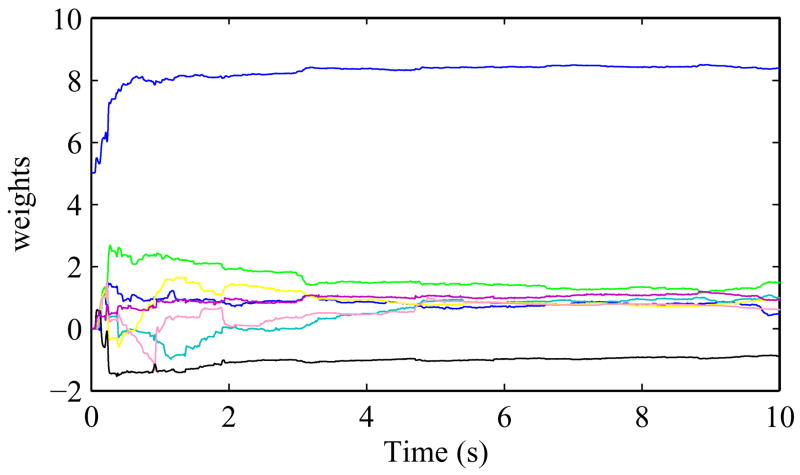
A number of simulations with a few random input waves are also performed for a range of values for the weights of the play operators. The weights of the hysteretic plant are varied within a bound from the actual values. The parameters of a P885.90 piezoelectric actuator is modeled and the parameters are found to be a⃗p = [8.4 1.3 0.92 0.7 0.88 0.74 − 2.6 2.23] and b⃗p = [−0.9 1.03 − 0.244 0.1 0.05 − 0.02 0.01 − 0.01]. It is found that convergence will occur for a typical P885.90 piezoelectric actuator if the random wave input is bounded in the range of [0–30]μm with velocity in the range [0–300]μm/s. A typical convergence of the weights is shown in Fig. 8. Thus, it can be seen that as long as the input and weights are bounded, convergence will occur for the adaptive controller.
Fig. 8.
A typical weight convergence
5 Experimental Results
In this section, a brief description of the experiment setup is first given, followed by the results. The behavior of the piezoelectric actuator P885.90 from Physik Instrumente is used to demonstrate the adaptive rate-dependent feed-forward controller.
5.1 Experimental Setup
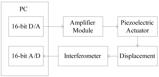
As seen from Fig. 9, a 16-bit D/A card is used to generate the necessary voltage, which is then passed through the amplifier (the gain is approximately 10). Given the voltage, the actuator will deform and the interferometer will detect the displacement and convert it to analog voltage signal. Using a 16-bit A/D card, the PC reads in the displacement.
Fig. 9.
Experimental Architecture
To perform tracking control, real-time operating system QNX Neutrino is used. The sampling rate of the DAQ card is set at 10 kHz. A timer interrupt is set at an interval of 0.5 ms (2 kHz) to average the data collected and update the parameters. The averaging acts a form of filtering.
5.2 Experimental Results
Experiments are conducted to demonstrate the performance of the adaptive feedforward controller. The objective of the actuator is to actuate according to a desired motion. In all the experiments conducted for this paper, the parameters of the actuator are treated as unknown. The first term of vector a⃗ is initialized as 5 whilst all the remaining terms in the vectors a⃗ and b⃗ are all initialized as 0.
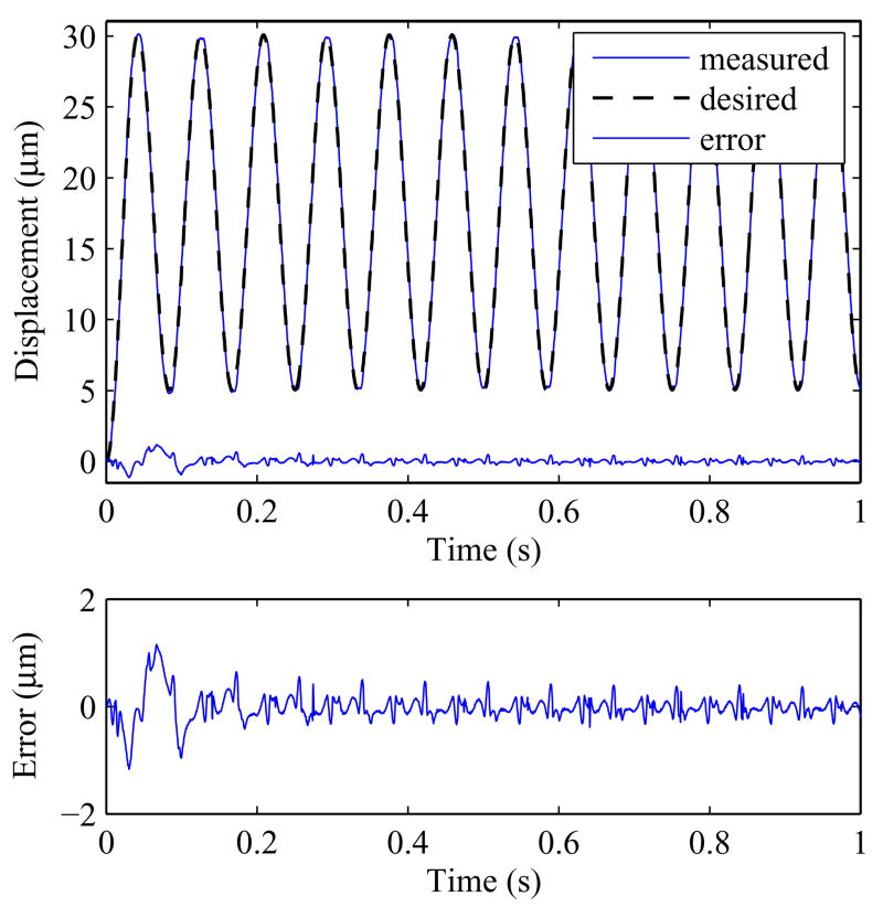
The first experiment is to actuate the actuator in a periodic sinusoidal motion. Fig. 10 shows the outcome and table 1 summarize the result. The rmse is found to be 0.1211 m between the time of 0.75s to 1s. The rmse will continue to drop if more adaptation time is permitted. The rmse from time 10s to 20s is 0.0584 μm, which is near to the interferometer’s noise level. Using a sensor with lower noise and better resolution might be able to reduce the rmse.
Fig. 10.
Tracking result of a 12Hz sinusoidal wave.
Table 1.
Measured Performance of the Adaptive Rate-Dependent Controller in Tracking Sinusoidal Waveforms
| 4 Hz | 8Hz | 12Hz | |
|---|---|---|---|
| rmse(μm) | 0.0638 | 0.0619 | 0.0584 |
| rmse/actuator’s stroke length | 0.0028 | 0.0026 | 0.0027 |
The rmse and max errors are the results taken from over a span from 10s to 20s.
In the first experiment, the desired motion is a periodic motion. However, the desired motions in many industrial applications are random and non-periodic. Thus, the adaptive feedforward controller was tested with a number of randomly created desired waveform motions. These waveforms are created by first generating random numbers using a Matlab function (rand), which can be assumed to be uniformly distributed random numbers. These values are then passed through a low pass filter, with a cutoff frequency of 20Hz, to remove the higher frequency components and smoothen out the points. Random numbers are used to ensure that the waveform is not periodic. This is where the rate-dependent phenomena play a role in the adaptive feedforward controller.
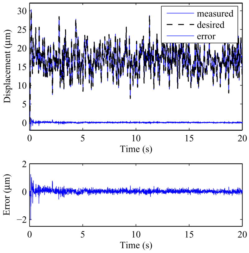
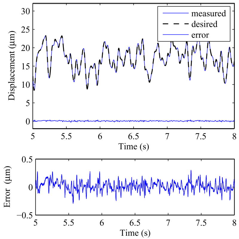
Five different waves were randomly created. Fig. 11 shows how the weights converge while Fig. 12 shows the tracking performance of the adaptive feed-forward controller for one of the waveforms. A section between time 5s and 8s is shown in Fig. 13. The result is summarized in Table 2. A wide time span of 10s to 20s is used to calculate the result for better representation. The mean rmse of the 5 different non-periodic motions is found to be 0.0943 μm with σ = 0.0159. The mean of the maximum errors is 0.3899 μm with σ = 0.0291.
Fig. 11.
Convergence of the weights of the adapting mechanism in the actual experiment.
Fig. 12.
Experimental results of a randomly created non-periodic wave. The different non-periodic waves are created by passing random numbers through a low pass filter.
Fig. 13.
A section of Fig. 12 between time 5s to 8s.
Table 2.
Measured Performance of the Adaptive Rate-Dependent Controller in Tracking Randomly Created Waveforms
| Adaptive Rate-Dependent Controller | |
|---|---|
| rmse ± σ(μm) | 0.0943 ± 0.0159 |
| rmse/peak-peak (%) | 0.33 |
| max error ± σ (μm) | 0.3899 ± 0.0291 |
| max error/peak-peak (%) | 1.35 |
The rmse and max errors are the mean results over a set of 5 different random non-periodic waveform experiments. The error is calculated from time = 10s to 20s. The waveforms are created by passing random numbers through a low-pass filter. The peak-peak is obtained as the difference between the maximum and minimum during this 10s interval of the random non-periodic waveforms.
6 Discussion
Most controllers like PID controllers introduce phase difference. Phase difference comes with higher tracking error. The proposed adaptive hysteresis feedforward controller is suitable for tracking purpose as no phase difference is introduced.
In this paper, the actuator is actuated in accordance to the randomly created non-periodic waveform. Thus, there is no prior knowledge of the desired motion and the motion is non-periodic. The purpose of choosing non-periodic waveform is to illustrate the rate-dependent ability of the adaptive feedforward control. As illustrated in the experiments, although the hysteretic plant (actuator) is treated as unknown, the adaptation speed of the feedforward controller is less than a second. The convergence speed is dependent on the waveform. A good learning waveform at the beginning will shorten the convergence time. Different adapting mechanism/law can be used too. In this paper, RLS is used as it is a simple and good algorithm with fast convergence time to implement. The author had also implemented least mean square (LMS) as the adapting mechanism. Although LMS is more robust to sudden changes, the steady state error is not as low and also the environmental conditions do not often change abruptly.
However, there are two main limitations. The input signals must satisfy the persistent excitation condition. In addition, to obtain the inverse parameters, it is assumed that the gradient at all the points are positive. In other words, the sum of weights at any point is assumed to be positive. Negative gradients must be avoided at all times. [23] can be implemented to account for the negative gradients at the turning point due to high speed. The authors plan to modify [23] to account for negative gradients at other location due to the adapting mechanism and implement in this controller
7 Conclusion
The hysteretic behavior of a piezoelectric actuator changes with rate, environmental conditions and age. Thus, an adaptive rate-dependent hysteresis feedforward controller for hysteretic plants is proposed and presented. This is achieved by adapting the coefficients that relate rate to the weights of the play operators to suit the environment. Actual implementation of the adaptive controller was carried out on a piezoelectric actuator. The main contribution of this paper over other present adaptive controllers is its ability to perform tracking control of non-periodic motion. The rate-dependent property of the adaptive feedforward controller was illustrated with the tracking control ability of non-periodic waveforms which most controllers are unable to perform.
Acknowledgments
This work was supported in part by College of Engineering, Nanyang Technological University, in part by Agency for Science, Technology and Research (A*START) SERC grant, and in part by NIH Grant R01EB000526 and R21EY016359. The author would also like to thank Dr. Klaus Kuhnen from University of Saarland, Germany, for clearing the author’s doubt on some issues.
Biographies
U-Xuan Tan received the B.Eng. degree in mechanical and aerospace engineering from the Nanyang Technological University, Singapore, in 2005. He is currently working towards the Ph.D. degree at Nanyang Technological University, Singapore. His research interests include mechatronics, control systems, smart materials, sensing systems, medical robotics, rehabilitative technology, mechanism design, kinematics, and signal processing.
Win Tun Latt received the B.E (Electronics) degree from Yangon Technological University, Myanmar in 2000, and the M.Sc (Biomedical Engineering) degree from Nanyang Technological University, Singapore in 2004. He won a gold medal in Singapore Robotics Games 2005. He is currently working toward his Ph.D. degree in the area of biomedical robotics in Nanyang Technological University, Singapore. His research interests include sensing systems, medical robotics, and mechatronics.
Ferdinan Widjaja received the B.Eng. degree in computer engineering from Nanyang Technological University, Singapore, in 2005. He is currently working towards the Ph.D. degree at Nanyang Technological University, Singapore. His research interests include sensor fusion, signal processing applied to biomedical signals, and biomedical robotics.
ChengYap Shee received the B.Eng. and M.Eng. degrees in mechanical and production engineering from the Nanyang Technological University, Singapore, in 1979 and 1999, respectively. In 2000, he was part of the core software developer team for a startup in San Mateo, CA. Thereafter, he has worked on research projects that included code parallelization using message passing and multithreading on computer clusters for a cellular automata-based cardiac arrhythmia modeling, development of a laser-based fiber-optic polarimetric sensor instrument that measures polarization for online structural health monitoring, and the Singapore DNA Tree project, where mitochondrial and Y-DNA are sequenced and analyzed to study the genetic diversity in Singapore. He has been a research associate with the Biorobotics Group, Nanyang Technolgoical University since 2005. His research interests span the areas of cellular automata and robotics.
Cameron N. Riviere received the B.S. degree in aerospace engineering and ocean engineering from the Virginia Polytechnic Institute and State University, Blacksburg, in 1989 and the Ph.D. degree in mechanical engineering from The Johns Hopkins University, Baltimore, MD, in 1995. Since 1995, he has been with the Robotics Institute at Carnegie Mellon University, Pittsburgh, PA, where he is presently an Associate Research Professor and the Director of the Medical Instrumentation Laboratory. He is also an adjunct faculty member of the Department of Rehabilitation Science and Technology at the University of Pittsburgh. His research interests include medical robotics, control systems, signal processing, learning algorithms, and biomedical applications of human-machine interfaces. Dr. Riviere served as one of the guest editors of the Special Issue on Medical Robotics of the journal proceedings of the IEEE in September 2006.
Wei Tech Ang received the B.Eng. and M.Eng. degrees in mechanical and production engineering from the Nanyang Technological University, Singapore, in 1997 and 1999, respectively, and the Ph.D. degree in robotics from Carnegie Mellon University, Pittsburgh, PA, in 2004. He has been an Assistant Professor in the School of Mechanical and Aerospace Engineering, Nanyang Technological University, since 2004. His research interests include sensing and sensor, actuators, medical robotics, rehabilitative and assistive technology, mechanism design, kinematics, signal processing, and learning algorithms.
Footnotes
Publisher's Disclaimer: This is a PDF file of an unedited manuscript that has been accepted for publication. As a service to our customers we are providing this early version of the manuscript. The manuscript will undergo copyediting, typesetting, and review of the resulting proof before it is published in its final citable form. Please note that during the production process errors may be discovered which could affect the content, and all legal disclaimers that apply to the journal pertain.
References
- 1.Dong W, Sun LN, Du ZJ. Design of a precision compliant parallel positioner driven by dual piezoelectric actuators. Sensors and Actuators A: Physical. 2007;135:250–256. [Google Scholar]
- 2.Landauer R, Young DR, Drougard ME. Polarization reversal in the barium titanate hysteresis loop. Journal of Applied Physics. 1956;27(71):752–758. [Google Scholar]
- 3.Smith RC, Ounaies Z, Wieman R. A Model for Rate-dependent Hysteresis in Piezoceramic Materials Operating at Low Frequencies. Technical Report, NASNCR-2001–211–62; NASA Langley Research Center. 2001. [Google Scholar]
- 4.Song G, Zhao J, Zhou X, Abreu-Garcia JAD. Tracking control of a Piezoceramic Actuator with Hysteresis Compensation using inverse Preisach Method. IEEE/ASME Transactions on Mechatronics. 2005 April;10 [Google Scholar]
- 5.Choi GS, Kim HS, Choi GH. A Study on Position Control of Piezoelectric Actuator based on anew mathematical model. Int. Symposium on Industrial Electronics; Guimaraes, Portugal. 1997. [Google Scholar]
- 6.Sun L, Ru C, Rong W, Chen L, Kong M. Tracking Control of Piezoelectric Actuator based on a new mathematical model. Journal of Micromechanics and Microengineering. 2004;14(11):1439–1444. [Google Scholar]
- 7.Ru C, Sun L. Hysteresis and creep compensation for piezoelectric actuator in open-loop operation. Sensors and Actuators A: Physical. 2005;122:124–130. [Google Scholar]
- 8.Hu H, Ben-Mrad R. On the Classical Preisach Model for hysteresis in piezoceramic actuators. Mechatron. 2002;13:85–92. [Google Scholar]
- 9.Hughes D, Wen JT. Preisach Modeling of Piezoceramic and Shape Memory Alloy Hysteresis. 4th IEEE Conf. on Control Applications; 1995. [Google Scholar]
- 10.Tan X, Baras JS. Adaptive Identification and Control of Hysteresis in Smart Materials. IEEE Transactions on Automatic Control. 2005 June;50(6):827–839. [Google Scholar]
- 11.Tan X, Baras JS. Modeling and control of hysteresis in magnetostrictive actuators. Automatica. 2004:1469–1480. [Google Scholar]
- 12.Goldfarb M, Celanovic N. A lumped parameter electromechanical model for describing the nonlinear behavior of piezoelectric actuators. Journal of Dynamics, Systems, Measurements and Control. 1997;119(3):478–485. [Google Scholar]
- 13.Tao G. Adaptive Control of Plants with Unknown Hystereses. IEEE Transactions on Automatic Control. 1995 [Google Scholar]
- 14.Feng Y, We TX, Hu YM, Su CY. Adaptive backstepping control of a class of uncertain nonlinear systems with Prandtl-Ishlinskii hysteresis. 4th International Conference on Machine Learning and Cybernetics; Guangzhou, China. Aug., 2005.pp. 69–71. [Google Scholar]
- 15.Zhao X, Tan Y. Neural network based identification of Preisach-type hysteresis in piezoelectric actuator using hysteretic operator. Sensors and Actuators A: Physical. 2006;126:306–311. [Google Scholar]
- 16.Liaw HC, Shirinzadeh B, Smith J. Enhanced sliding mode motion tracking control of piezoelectric actuators. Sensors and Actuators A: Physical. 2007;138:194–202. [Google Scholar]
- 17.Kuhnen K. Modeling, Identification and Compensation of Complex Hysteretic Nonlinearities: A modified Prandtl-Ishlinskii Approach. European Journal of Control. 2003;9(4):407–418. [Google Scholar]
- 18.Kuhnen K, Janocha H. Inverse Feedforward Controller for Complex Hysteretic Nonlinearities in Smart-Material Systems. Control and Intelligent System. 2001;29:74–83. [Google Scholar]
- 19.Krejci P, Kuhnen K. Inverse Control of System with Hysteresis and Creep. IEE Proc of Control Theory and Applications. 2001 May;148(3):185–192. [Google Scholar]
- 20.Kuhnen K, Janocha H. Adaptive Inverse Control of Piezoelectric Actuators with Hysteresis Operators. Euro. Control Conf. ECC’99; Germany. 1999. [Google Scholar]
- 21.Ang WT, Riviere CN, Khosla PK. Feedforward Controller with Inverse Rate-Dependent Model for Piezoelectric Actuators in Trajectory Tracking Applications. IEEE/ASME Transactions on Mechatronics. 2007 April;12(2):1–8. [Google Scholar]
- 22.Haykin S. Adaptive Filter Theory. 3. Prentice Hall; New Jersey: 1996. [Google Scholar]
- 23.Tan UX, Win TL, Ang WT. Modeling Piezoelectric Actuator Hysteresis with Singularity Free Prandtl-Ishlinskii Model. IEEE Int. Conf. on Robotics and Biomimetics; Kunming, China. 2006. pp. 251–256. [Google Scholar]


