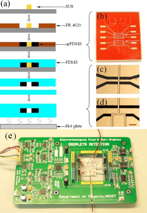
Figure 8.
(a) Flow chart of the microfluidic chip fabrication with parallel electrodes using soft lithography for droplet detection and control. (b) An optical image of the channel mold and conductive components. (c) and (d) are optical images of the droplet detection area and directional flow control area. The scale bar in (d) is 200 μm. (e) An optical image of the circuit board and the mounted chip for droplet detection (Ref. 71).

