Abstract
Concentric annular type dual element transducers for second harmonic imaging at 20 MHz / 40 MHz were designed and fabricated to improve spatial resolution and depth of penetration for ophthalmic imaging applications. The outer ring element was designed to transmit the 20 MHz signal and the inner circular element was designed to receive the 40 MHz second harmonic signal. Lithium niobate (LiNbO3), with its low dielectric constant, was used as the piezoelectric material to achieve good electrical impedance matching. Double matching layers and conductive backing were used and optimized by KLM modeling to achieve high sensitivity and wide bandwidth for harmonic imaging and superior time-domain characteristics. Prototype transducers were fabricated and evaluated quantitatively and clinically. The average measured center frequency for the transmit ring element was 21 MHz and the one-way –3 dB bandwidth was greater than 50%. The 40 MHz receive element functioned at 31 MHz center frequency with acceptable bandwidth to receive attenuated and frequency downshifted harmonic signal. The lateral beam profile for the 20 MHz ring elements at the focus matched the Field II simulated results well, and the effect of outer ring diameter was also examined. Images of a posterior segment of an excised pig eye and a choroidal nevus of human eye were obtained both for single element and dual element transducers and compared to demonstrate the advantages of dual element harmonic imaging.
I. INTRODUCTION
Tissue harmonic imaging has been accepted as one of standard imaging modalities in many applications since its introduction to medical ultrasound imaging in the 1990s [1]. Especially in cardiac and abdominal studies, tissue harmonic imaging is very often used for diagnostics along with fundamental imaging. By utilizing the second harmonic component of the receive signal, images can be improved by reducing near field reverberation, decreasing phase aberration error, and improving border delineation [1]. Recently, harmonic imaging has been used in ophthalmic [2], urologic [3], and intravascular ultrasound (IVUS) [4] imaging studies.
A variety of specially designed transducers dedicated to harmonic imaging have been reported recently. A lithium niobate (LiNbO3) plate transducer with a local ferroelectric inversion layer produced by titanium diffusion and heat treatment was proposed for 50 MHz transmit and 100 MHz receive harmonic imaging [5]. A multilayer transducer with a PZT layer used for transmission and a PVDF layer used for reception was reported for bladder volume assessment [3]. An oval shape PZT transducer with additional passive mismatching layers for intravascular ultrasound (IVUS) was also reported for 20 MHz/40 MHz harmonic imaging [4].
Ophthalmic imaging can be separated into two categories: anterior segment imaging and posterior segment imaging. Currently available commercial ultrasonic biomicroscopy (UBM ) systems use 35 to 50 MHz transducers for anterior segment imaging [6], whereas 10 to 20 MHz transducers are used for imaging the posterior segment. Imaging of the posterior segment shows a greater need for improved spatial resolution and depth of penetration for proper diagnosis of retinal disease, such as age related macular degeneration, detached retina, and diabetic retinopathy [2].
Recently, broadband lithium niobate single element transducers operating at about 20 MHz have been used for imaging the posterior segment of the eye [7], but were limited due to the spatial resolution at that frequency. As an alternative to fundamental imaging, harmonic imaging was also examined [2]. Unfortunately, transducers operating at 20 MHz may not provide the spatial resolution needed to adequately delineate layers on the posterior segment of the human eye, and, on the contrary, those operating in the higher frequency range do not provide sufficient depth of penetration. In this study, we propose to resolve this problem by creating a concentric annular type dual element transducer for second harmonic imaging of the posterior segment of the eye. The outer ring element is used for transmit and the inner circular element for receive. A ring-shaped outer element produces higher sidelobes than does a circular element of the same diameter, but this is to some degree compensated for by the inherently lower sidelobes in the harmonic compared with the fundamental [8].
Multiple prototype dual element transducers for harmonic imaging have been fabricated and tested. Different apertures, different matching layer thicknesses, and different fabrication techniques have been experimented with to optimize performance. Clinical images of various cases were obtained and compared with fundamental imaging.
II. DESIGN AND FABRICATION
A. Design
A concentric annular type dual element structure was chosen to satisfy the need to have two separate transducers in one housing. Those two elements should have identical beam axis and focal point to obtain echoes from the same image plane while functioning at different frequencies. The transducer also should have two separate connectors since their use is dedicated for transmit and receive respectively.
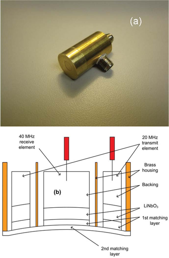
Fig. 1(a) shows that the outer ring element and the inner circular element were placed in a brass housing and have separate connectors. The outer ring element was designed to transmit a 20 MHz signal and the inner circular element was designed to receive the second harmonic signal at 40 MHz. Fig. 1(b) is the cross-sectional drawing of this transducer. The outer diameter of the transmit ring element was set to be 10.0 mm or 12.0 mm (See Options 1 and 2 in Table I). The inner diameter was 5.4 mm. The center was filled by the 5.0-mm-diameter receive element.
Fig. 1.
Dual element transducer: (a) photograph of the finished device, (b) cross-sectional drawing of the transducer (not to scale).
TABLE I.
Design Parameters for Dual Element Transducers.
| Option 1 (Dout = 10 mm) | Option 2 (Dout = 12 mm) | ||||
|---|---|---|---|---|---|
| Layer | Material | 20 MHz Transmit |
40 MHz Receive |
20 MHz Transmit |
40 MHz Receive |
| Piezo | LiNbO3 | 150 | 77 | 150 | 77 |
| 1st M/L | Silver epoxy Ia | 23 | 12 | 23 | 12 |
| 2nd M/L | Parylene | 19 | 19 | 14 | 14 |
| Backing | Silver epoxy IIb | N/A | N/A | N/A | N/A |
M/L: Matching layer. Numerical values in table are layer thicknesses, given in micrometers.
Insulcast 501 + 2–3 µm silver particles.
E-Solder 3022 (centrifuged).
KLM modeling software (PiezoCAD, Sonic Concepts, Woodinville, WA) was used to determine the aperture size, and the proper thicknesses of the lithium niobate, inner silver epoxy matching layer, and parylene outer matching layer. A more detailed description of the materials used in the design can be found in [9]. The diameter of each element was chosen to match its electrical impedance at the given frequency to 50 Ω. As described by Cannata et al. [9], lithium niobate is a good material to use in large-aperture high frequency transducer designs since it has a low relative clamped dielectric constant (ε33 S/ε0) of 39, a high longitudinal sound speed (cl) of 7340 m/s, and a comparable thickness mode electromechanical coupling coefficient (kt) of 0.49 to PZT-5H. The radius of curvature for both transmit and receive elements was set to 30 mm to place the focal point at the retina in immersion mode scanning.
The thicknesses of the lithium niobate layer and the first matching layer of the transmit element were optimized for 20 MHz and those of the receive element for 40 MHz. The thickness of the second matching layer was chosen to be intermediate to the ideal calculated for 20 MHz and 40 MHz (See Option 1 in Table I), since the same layer thickness would be applied to both the inner element and outer ring to ease construction. The thickness of parylene optimized at 40 MHz (See Option 2 in Table I) was also investigated to improve the performance of the receive element. Table I shows the summary of design parameters.
B. Fabrication
Two 36° rotated Y-cut lithium niobate plates (Boston Piezo-Optics, Bellingham, MA) with thickness of 500 µm each were prepared, one for the 20 MHz transmit and the other for the 40 MHz receive element. Lithium niobate plates were lapped to the designed thicknesses, 150 µm for 20 MHz and 77 µm for 40 MHz, and electroplated with a 1500 Å chrome/gold (Cr/Au) layer on both sides by an NSC-3000 automatic sputter coater (Nano-Master, Austin, Tx). The silver epoxy inner matching layer, made from a mixture of Insulcast 501 epoxy (American Safety Technologies, Roseland, NJ) and 2 to 3 µm silver particles (Aldrich Chemical Co., Milwaukee, WI) with the weight ratio of 2.5 to 6, was cast over the lithium niobate plates after applying an adhesion promoter (Chemlok AP-131, Lord Corp., Erie, PA). The epoxy was then centrifuged at 3000 rpm for 10 min. After curing, the matching layers were lapped down to the desired thickness. The lapped piezo/first matching stack plates were mechanically diced into square pieces with the size that would encompass a ring or a circular element. A conductive silver epoxy (E-Solder 3022, Von Roll Isola Inc., New Haven, CT) backing layer was then cast and centrifuged onto the back side of the electroplated pieces of lithium niobate. After curing, the backed/matched pieces of lithium niobate were carefully drilled to the desired inner diameter of the ring and turned down to the outer diameter of the ring on a lathe to create the 20 MHz transmit element. The 40 MHz inner circular element was also turned down to the proper diameter. A protective piece of machinable ceramic was waxed to the top of the stack to reduce chipping during the drilling and turning down stages. A thin brass cylinder was fabricated and placed between the transmit and receive elements to provide RF shielding. Machined transmit and receive acoustic stacks were placed in the brass housing concentrically, and the gaps between stacks were filled in by an insulating epoxy (Epo-Tek 301, Epoxy Technologies, Billerica, MA).
Press-focusing was used to generate a mechanical focus at 30 mm for both transmit and receive elements [9]. The transducer surface was sputtered with Cr/Au electrodes to make ground connection between the elements and the brass housing. The outer parylene layer was then deposited using a PDS 2010 Labcoater (SCS, Indianapolis, IN). The finished transducer elements were connected by 2 separate SMA connectors, one for transmit and the other for receive.
In addition, 20 MHz single element transducers of the same total diameter and similar acoustic characteristics as the transmit ring element were fabricated for comparison.
III. TRANSDUCER PERFORMANCE
The transmit and receive elements were characterized by a one-way sound field measurement with a hydrophone, two-way pulse-echo test with a soft target for harmonic generation, and a Schlieren image test for visualizing the beam profile [10]. The transmit sound field data for dual element transducers were compared with those of single element transducers to determine the effect of the ring shape. Round-trip lateral beam profiles of dual element transducers with harmonic imaging were simulated and compared with fundamental imaging using single element transducers.
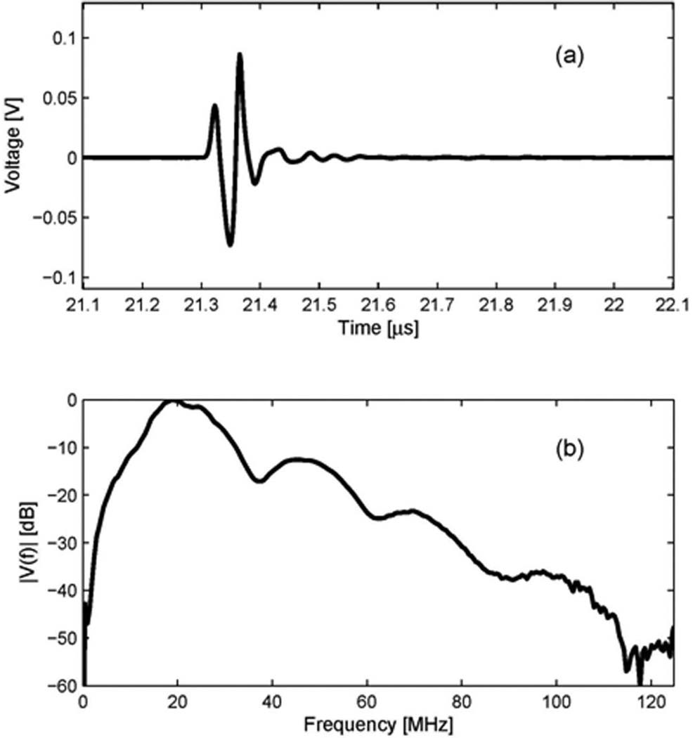
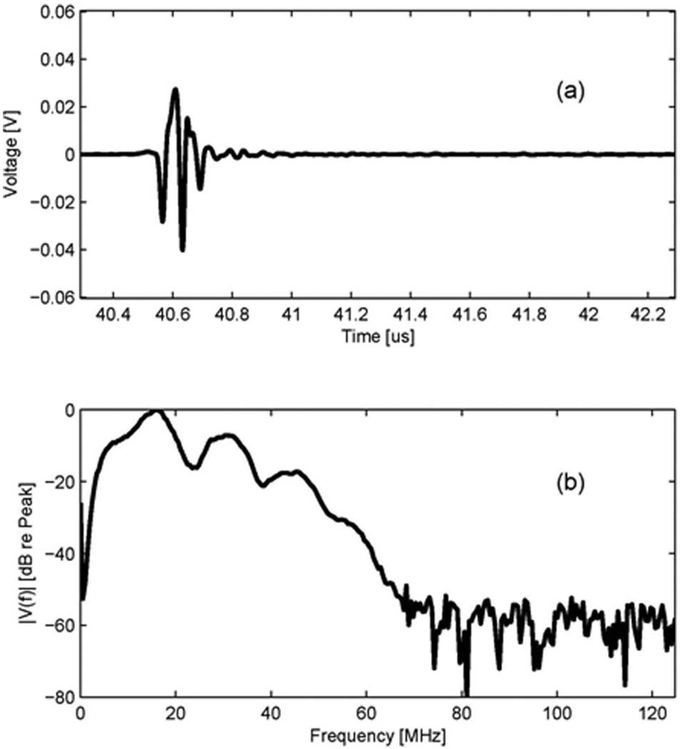
The transmit beam of the 20 MHz outer ring element at the focal point was measured with a needle hydrophone (HGL-0085, Onda Corp., Sunnyvale, CA). In this measurement, an ultrasonic analyzer (5900PR, Panametrics Inc., Waltham, MA) was used to excite the transducers, and a digital oscilloscope (LC534, LeCroy Corp., Chestnut Ridge, NY) was used to record the waveform acquired by the hydrophone. The measurement was performed in a degassed/deionized water tank. After the hydrophone was aligned to be perpendicular to the beam axis of a transducer, the maximum peak-to-peak voltage point along the beam axis was located. The time-domain waveform at the maximum peak-to-peak voltage point was recorded and its spectrum was calculated. Fig. 2 shows the measured results for the 20 MHz transmit element. Its –3 dB center frequency is 21.0 MHz and –3 dB fractional bandwidth is 56%.
Fig. 2.
Transmit characteristic of the 20 MHz outer ring of the dual element transducer (Option 2: Dout = 12 mm): (a) a measured waveform by a hydrophone at the focal depth, (b) its spectrum.
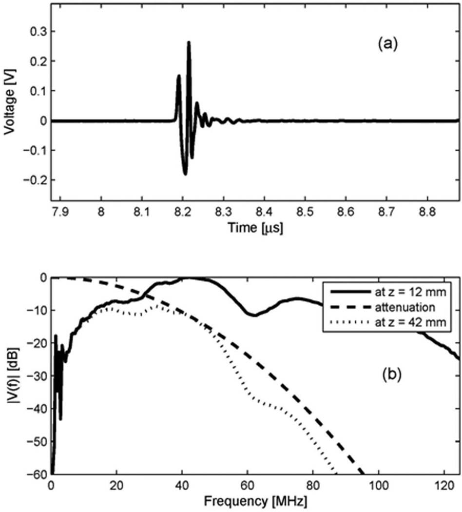
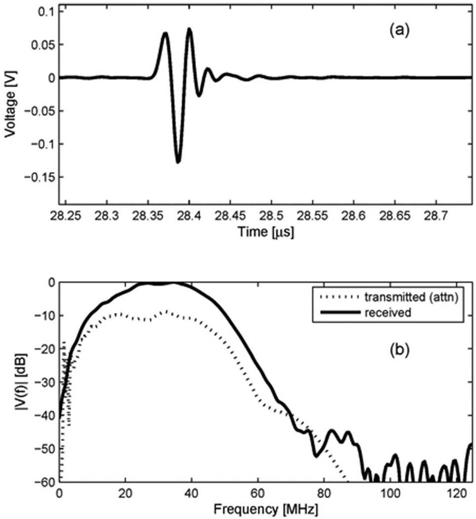
The receive characteristic of the 40 MHz inner circular element was measured by utilizing a separate source transducer. Special test settings were configured to check if the receive element had proper center frequency and bandwidth to receive the second harmonic signal centered at 40 MHz. A 40 MHz single element transducer (diameter = 4 mm, focus = 12 mm) was used as a source, and the receive element as a receiver. The distance between source and receiver for this measurement was determined by the sum of focal distances from each transducer. The focused beam at 12 mm from the source travels 30 mm to reach the surface of receiver. Therefore, a comparison of the spectra acquired by the hydrophone and the receive element would yield the receive characteristic of the receive element. However, with the hydrophone, it was difficult to acquire enough signal strength at that distance (42 mm) since the beam diverges significantly after the focal point. Instead, the beam was measured with the hydrophone placed at the focal point of 12 mm, as shown in Fig. 3(a). Its spectrum was calculated, and the attenuation of water (2.2 × 10⁻³ dB/cm/MHz2) [11] was taken into account to approximate the signal spectrum incident to the surface of the receive element. Fig. 3(b) shows the spectrum of Fig. 3(a) (at z = 12 mm), the attenuation curve vs. frequency in the water at the distance of 30 mm (attenuation), and the attenuated spectrum at the surface of the receive element, z = 42 mm (at z = 42 mm). The waveform acquired by the receive element at 42 mm is shown in Fig. 4(a), and its spectrum is shown as a solid line in Fig. 4(b). Also shown in Fig. 4(b), as a dotted line, is the attenuated spectrum at the surface of the receive element, shown earlier in Fig. 3(b). The spectrum of the received signal is centered at 30.5 MHz. Comparing the input (a dotted line) and the output (a solid line) of the receive element, we can say that the receive element has an acceptable bandwidth to pass spectral components centered at approximately 30 MHz. This frequency characteristic of the receive element allows extracting the second harmonic signal with maximum achievable signal-to-noise ratio by a digital bandpass filter. Although the −3 dB frequencies in the one-way spectrum of the receive element are approximately 20 MHz and 43 MHz, the receive signal in the range between 25 MHz and 45 MHz is mainly amplified, as shown in Fig. 4(b). Therefore, we designed a 33-tap FIR bandpass filter with cutoff frequencies of 25 MHz and 45 MHz, which was used to produce harmonic images for clinical evaluation.
Fig. 3.
Transmit characteristic of the 40 MHz single element source transducer: (a) a measured waveform by a hydrophone at the focal depth of the source transducer (z = 12 mm); (b) its spectrum (at z = 12 mm), the attenuation curve vs. frequency in the water at the distance of 30 mm (attenuation), and the attenuated spectrum at the surface of receive element, z = 42 mm (at z = 42 mm).
Fig. 4.
Receive characteristic of the 40 MHz inner circular element of the dual element transducer: (a) a received waveform by the receive element, (b) an attenuated spectrum of the signal from the source transducer and a spectrum of the received signal of receive element.
Fig. 5 and Fig. 6 demonstrate the advantage of dual element structure over single element for second harmonic imaging. The pulse-echo test data for the dual element transducer show a clearly identified second harmonic component which is not visible with the single element transducer. A soft silicone rubber target was used to generate harmonic components. When the silicone rubber target was used, a higher voltage could be applied for the transmit signal than when the quartz target was used. The echo signal was easily saturated from the quartz target since it has a stronger reflection than the silicone rubber. Therefore, the higher transmit voltage with the silicone rubber target resulted in the increased nonlinearity of the echo since the level of the second harmonic component (the degree of nonlinearity in tissue harmonic imaging) is proportional to the mechanical index (MI) [1]. The MI is defined as where pr.3(zsp) is the peak rarefactional pressure in MPa derated by 0.3 dB/cm-MHz to the point on the beam axis, zsp, where the pulse intensity integral is maximum; fc is the center frequency in MHz [12]; and the MI is directly proportional to the transmit voltage.
Fig. 5.
Pulse-echo test results using the 20 MHz outer ring element for transmission and reception (Option 2: Dout = 12 mm): (a) an echo waveform from the soft silicone rubber target at the focal depth, (b) its spectrum.
Fig. 6.
Pulse-echo test results for the dual element transducer using the 20 MHz outer ring element for transmission and the 40 MHz inner circular element for reception (Option 2: Dout = 12 mm): (a) an echo waveform from the soft silicone rubber target at the focal depth, (b) its spectrum.
Fig. 5 shows a pulse-echo signal and its spectrum obtained by transmitting and receiving with a 20 MHz outer ring element only. The spectrum has a center frequency of 15.6 MHz and a very low second harmonic component because of an insufficient bandwidth of the transducer for the second harmonic imaging. Fig. 6 shows a pulse-echo signal and its spectrum obtained by transmitting with the 20 MHz outer ring element and receiving with 40 MHz inner circular element. In the spectrum obtained with the dual element transducer in Fig. 6(b), the magnitude of the second harmonic component centered at 30.5 MHz is 7 dB lower than that of the fundamental component. These results demonstrate that the dual element transducer is capable of efficiently receiving the second harmonic component and thus improving image quality due to its adequate sensitivity and bandwidth.
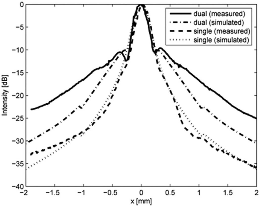
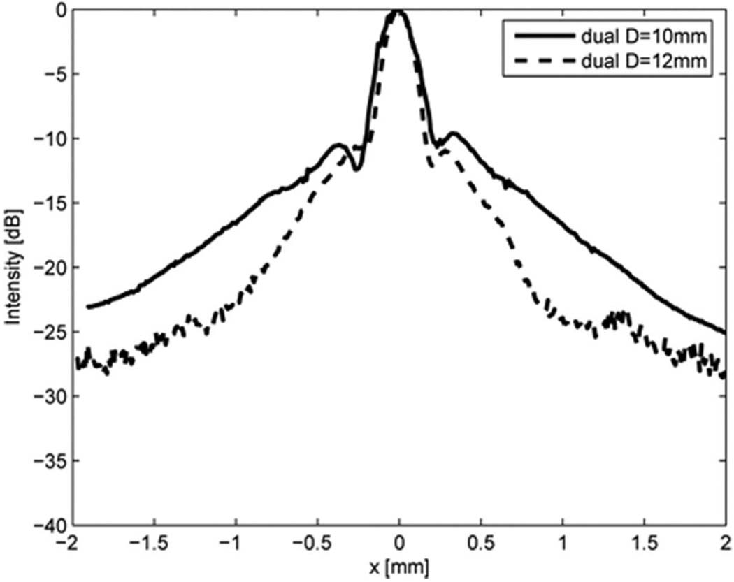
To evaluate the transmit sidelobe level of the 20 MHz ring element, its lateral beam profile was also measured by a needle hydrophone at its focal point and compared with that of a full-aperture 20 MHz single element transducer. As shown in Fig. 7, the sidelobe level for the ring element is higher than that of the full-aperture single element transducer. Measured results were also compared with the simulated lateral beam profiles generated by Field II [13]. As evident in the figure, the simulated and measured results are fairly well matched. The sidelobe level of the dual element transducer measured at x = 0.33 mm was −9.6 dB, whereas that of the single element transducer was −14.7 dB. Fig. 8 shows the effect of outer ring diameter on the lateral beam pattern. By increasing the outer diameter from 10 mm to 12 mm, the mainlobe energy was increased and the sidelobe level was reduced significantly.
Fig. 7.
Lateral beam profiles obtained by the transmit waveforms at the focus from the 20 MHz outer ring of the dual element transducer (Option 1: Dout = 10 mm) and the 20 MHz circular shape single element transducer, measured by a hydrophone and simulated by Field II.
Fig. 8.
Lateral beam profiles obtained by the transmit waveforms at the focus of dual element transducers for different outer diameters of the 20 MHz outer ring element (Option 1: Dout = 10 mm vs. Option 2: Dout = 12 mm).
Although the transmit element was ring shaped and the increased sidelobe level was anticipated, harmonic imaging led to a reduction of the sidelobe level and resulted in comparable improvement in lateral resolution [8].
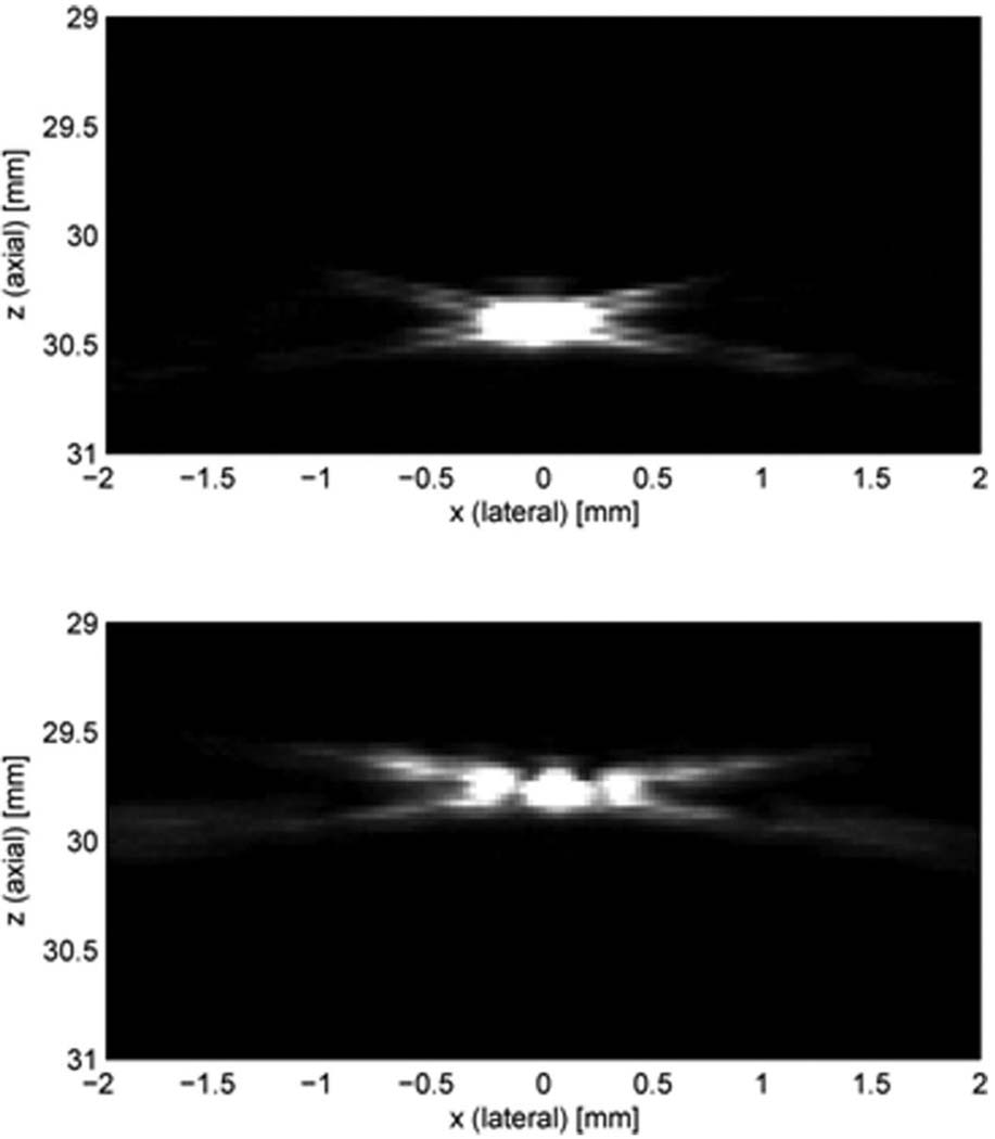
Schlieren imaging is a more efficient tool for visualizing the sound field [10]. Multiple images were obtained with a high frequency Schlieren imaging system (Optison Beam Analyzer – High Frequency Option, Onda Corp., Sunnyvale, CA). From the transmit beam patterns of circular and ring shape transducers at the focus shown in Fig. 9, which is an uncompressed 256 gray-scale image, it is clearly seen that the ring shape transducers generate higher sidelobe levels than circular shape transducers. This result correlates well with the previous evaluation for the lateral beam profiles obtained with the hydrophone measurement and Field II simulation.
Fig. 9.
Schlieren images of the 20 MHz circular and ring shape elements (Option 2: Dout = 12 mm), uncompressed and linearly mapped to a 256-level gray scale: (a) circular, at the focal depth; (b) ring, at the focal depth.
IV. CLINICAL EVALUATION
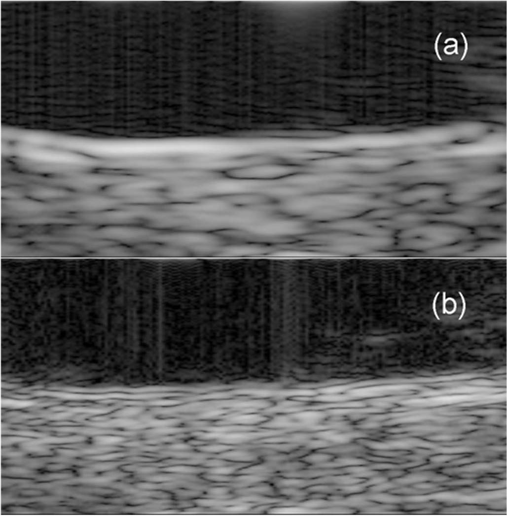
The performance of the dual element transducer was evaluated with images of the posterior segment of the excised pig eye. The excised pig eye was cut in half to remove the anterior segment, and only the posterior segment was placed in the water tank. The Panametrics 5900PR was used to excite the 20 MHz ring element and the LC534 digital oscilloscope was used to record the echo signals received by the 40 MHz circular element obtained by sampling at 500 MHz. To acquire 400 scan lines for harmonic imaging, a stepper motor repeatedly translated the dual element transducer by 25 µm along the horizontal direction. For the comparison, another 400 scan lines were also acquired with a 20 MHz single element transducer in the same manner. The 2 sets of scan lines were used to form a harmonic and a fundamental image, respectively. Fig. 10 shows images of the posterior wall of the pig eye, covering an area of 3.0 mm × 1.5 mm in the vicinity of the focal depth of 30 mm. From Fig. 10, it is clearly evident that a harmonic image produced by the dual element transducer (b) has better spatial resolution and better border delineation capability than a fundamental image by the single element transducer (a).
Fig. 10.
Images of the posterior segment of an excised pig eye, 3.0 mm × 1.5 mm, in the vicinity of the focal depth of 30 mm, logarithmically compressed to a dynamic range of 60 dB and linearly mapped to a 256-level gray scale: (a) fundamental imaging using the single element transducer, (b) harmonic imaging using the dual element transducer (Option 2: Dout = 12 mm).
A study of in vivo human eyes was also performed with a custom-built imaging system [7], [14]. This study adhered to the tenets of the Declaration of Helsinki and was approved by the Institutional Review Board of the Weill Cornell Medical College.
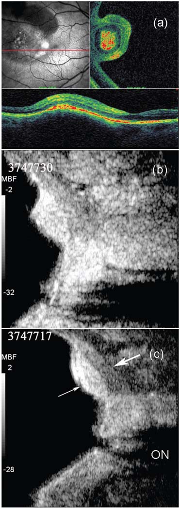
Fig. 11 shows the images of a choroidal nevus. The SLO image [Fig. 11(a), upper left] shows the retinal vasculature and a dark, disrupted, and roughly round area toward the left of the image. The OCT C-scan (upper right) is, like the SLO image, an en face representation, but, in this case, of a plane cutting through the retinal pigment epithelium, which is highly reflective and represented in red in the color-scale OCT images. The peninsular appearance of the region in the C-scan indicates that it is an elevated lesion. The OC T B-scan [Fig. 11(a), bottom] is in the plane of the horizontal red line drawn through the SLO image and is 1.5 mm in depth. It shows the retinal layers, including the pigment epithelium (red) overlying the lesion. The lesion itself is seen only as an elevation of the retinal contour, due to absorption of light by pigment. The macula is seen as a small dip to the right of the tumor.
Fig. 11.
Images of a choroidal nevus of the human eye: (a) images SLO and OCT; (b) fundamental imaging using the single element transducer; (c) harmonic imaging using the dual element transducer (Option 1: Dout = 10 mm; thin arrow: greater shadowing by the lesion; thick arrow: improved depiction of retina/sclera border; ON: optic nerve), logarithmically compressed to a dynamic range of 30 dB and linearly mapped to a 256-level gray scale.
Fig. 11(b) and (c) show the appearance of the lesion on the B-scan with a single element 20 MHz transducer by fundamental imaging (b) and the dual element transducer by harmonic imaging (c). The image, which is 6.3 mm in depth, was constructed from RF echo data acquired at a 250 MHz sample rate. We can observe greater shadowing by the lesion (thin arrow) and the improved depiction of the overlying retina and sclera border (thick arrow) in the harmonic image. The optic nerve (ON) cup is more clearly depicted in the harmonic image as well.
V. CONCLUSION
Concentric annular type 20 MHz/40 MHz dual element transducers for high frequency ophthalmic imaging were designed, fabricated, and evaluated. The concentric type dual element structure packaged in a single housing worked well as a dedicated harmonic imaging transducer. Although the ring shape of the transmit element generated increased sidelobe levels, this shortcoming was more than sufficiently compensated for by the advantage of harmonic imaging in suppressing sidelobes to achieve an improved lateral resolution.
Harmonic imaging with 20 MHz transmit and 40 MHz receive showed capability superior to that of fundamental imaging at 20 MHz to diagnose the retinal disease at the posterior segment of the eye. The center frequencies of transmit and receive elements of dual element transducers can be further optimized to match the designed center frequencies to support a larger dynamic range. The aperture size of transmit and receive elements can also be optimized with further experimentation to achieve the best combination of transmit and receive efficiency.
ACKNOWLEDGMENT
The authors thank Dr. Claudio Zanelli, Onda Corp., Sunnyvale, CA, for loaning us an Optison Beam Analyzer – High Frequency Option for this research conducted at the NIH Resource Center on Medical Ultrasonic Transducer Technology, University of Southern California, Los Angeles, CA.
Biographies

Hyung Ham Kim (S’93–M’95–S’04) received his B.S. degree in electrical engineering from Korea Advanced Institute of Science and Technology, Daejeon, Korea, in 1993; his M.S. degree in electrical engineering from Seoul National University, Seoul, Korea, in 1995; and his M.S. degree in biomedical engineering from University of Southern California, Los Angeles, CA, in 2006.
He served as the manager and principal engineer of the Probe Department at Medison Co., Ltd., in Seoul, Korea, from 1994 to 2004. He is currently pursuing his doctoral degree at the Department of Biomedical Engineering, University of Southern California. His current research interests include the design and fabrication of high frequency array transducers for medical imaging applications and acoustic output measurement for high frequency transducers.

Jonathan M. Cannata (S’01–M’04) received his B.S. degree in bioengineering from the University of California at San Diego in 1998, and his M.S. and Ph.D. degrees in bioengineering from the Pennsylvania State University, University Park, PA, in 2000 and 2004, respectively.
Since 2001 Dr. Cannata has served as the manager for the NIH Resource on Medical Ultrasonic Transducer Technology at the University of Southern California (USC). In 2005 he was appointed Research Assistant Professor of Biomedical Engineering at USC. His current interests include the design, modeling, and fabrication of high frequency single element ultrasonic transducers and transducer arrays for medical imaging applications.

Ruibin Liu was born in Kunming, Yunnan Province, China, on July 18, 1963. He received his Ph.D. degree in materials engineering from the Shanghai Institute of Ceramics, Chinese Academy of Sciences, in 1991.
From 1991 to 1996, he was an engineer at the Shanghai Institute of Ceramics. His research interest included development of pyroelectric ceramics for application in IR detection and imaging. From 1996 to 1999, he worked as a postdoctoral fellow in the Materials Research Laboratory of the Pennsylvania State University. His research interests included piezoelectric actuators, single crystal thin film, and electrostrictive polymers. From 1999 to 2000 and 2002 to 2003, he worked as a postdoctoral fellow and a research engineer, respectively, at the Sunnybrook & Women’s College Sciences Center, University of Toronto. His studies included composite and transducer for high frequency imaging. During 2000–2002, he worked as a partner of a start-up company Tradetrek.com.
During 12/2004–01/2008, he was a research associate at the NIH Ultrasound Transducers Resources Center at the University of Southern California. His research interests were high frequency (40–100 MHz) single element transducers, intracardiac imaging phased arrays, high frequency composites and arrays, HIFU single element transducers, and phased arrays.
He is currently a Senior Scientist at Blatek, Inc., in State College, Pennsylvania.

Jin Ho Chang (S’00–M’08) received his B.S. and M.S. degrees in electronic engineering from So-gang University, Seoul, South Korea, in 2000 and 2002, respectively. He obtained his Ph.D. degree in biomedical engineering from the University of Southern California, Los Angeles, CA, in 2007. From 2002 through 2003, he worked at the Digital Media Research Lab., LG Electronics Inc., Seoul, South Korea, as a research engineer. He is currently a postdoctoral research associate in the NIH Resource Center for Medical Ultrasonic Transducer Technology at the University of Southern California, Los Angeles, CA. His research interests include the development of a high frequency ultrasound imaging system, ultrasound signal processing, and ultrasound field analysis.

Ronald H. Silverman was born in New York City in 1950. He graduated from Brooklyn College with a B.S. degree in chemistry in 1971. He received a M.S. degree in bioengineering from the Polytechnic Institute of New York (Brooklyn, NY) in 1979 and a Ph.D. in computer science from the same institution in 1990.
Dr. Silverman has been working in the Department of Ophthalmology of the Weill Cornell Medical College (New York, NY) since 1983. His academic title is Professor of Computer Science in Ophthalmology. Dr. Silverman has also been a part-time member of the research staff of the Frederic L. Lizzi Center for Biomedical Engineering of the Riverside Research Institute (New York, NY) since 2005. Dr. Silverman’s research interests primarily involve high-resolution ultrasound imaging, tissue characterization, bioeffects, ultrasound-enhanced drug delivery, and acoustic-optical interactions. His interdisciplinary work ranges from basic engineering to animal and clinical studies.
Dr. Silverman is a Fellow of the American Institute of Ultrasound in Medicine and a member of the Program Committees of the Association for Research in Vision and Ophthalmology and the International Society for Imaging in the Eye. He is a member of the IEEE, SPIE, the American Academy of Ophthalmology, the International Neural Network Society, and the American Association for the Advancement of Science.

K. Kirk Shung (S’73–M’75–SM’89–F’93) obtained a B.S. degree in electrical engineering from Cheng-Kung University in Taiwan in 1968, an M.S. degree in electrical engineering from University of Missouri, Columbia, MO, in 1970, and a Ph.D. degree in electrical engineering from the University of Washington, Seattle, WA, in 1975. He did postdoctoral research at Providence Medical Center in Seattle, WA, for one year before being appointed a research bioengineer, holding a joint appointment at the Institute of Applied Physiology and Medicine. He became an assistant professor in the Bioengineering Program, Pennsylvania State University, University Park, PA, in 1979, and was promoted to professor in 1989. He was a Distinguished Professor of Bioengineering at Pennsylvania State University until September 1, 2002, when he joined the Department of Biomedical Engineering, University of Southern California, Los Angeles, CA, as a professor. He has been the director of NIH Resource on Medical Ultrasonic Transducer Technology since 1997.
Dr. Shung is a fellow of the IEEE, the Acoustical Society of America, and the American Institute of Ultrasound in Medicine. He is a founding fellow of the American Institute of Medical and Biological Engineering. He has served for two terms as a member of the NIH Diagnostic Radiology Study Section. He received the IEEE Engineering in Medicine and Biology Society early career award in 1985 and was the coauthor of a paper that received the best paper award for IEEE Transactions on Ultrasonics, Ferroelectrics, and Frequency Control (UFFC) in 2000. He was the distinguished lecturer for the IEEE UFFC Society for 2002–2003. He was elected an outstanding alumnus of Cheng-Kung University in Taiwan in 2001.
Dr. Shung has published more than 200 papers and book chapters. He is the author of a textbook Principles of Medical Imaging, published by Academic Press in 1992, and a textbook Diagnostic Ultrasound: Imaging and Blood Flow Measurements, published by CRC press in 2005. He co-edited a book Ultrasonic Scattering by Biological Tissues, published by CRC Press in 1993. Dr. Shung’s research interest is in ultrasonic transducers, high frequency ultrasonic imaging, and ultrasonic scattering in tissues.
Contributor Information
Hyung Ham Kim, NIH Resource Center on Medical Ultrasonic Transducer Technology, Department of Biomedical Engineering, University of Southern California, Los Angeles, CA 90036 (e-mail: hyungham.kim@usc.edu)..
Jonathan M. Cannata, NIH Resource Center on Medical Ultrasonic Transducer Technology, Department of Biomedical Engineering, University of Southern California, Los Angeles, CA 90036.
Ruibin Liu, NIH Resource Center on Medical Ultrasonic Transducer Technology, Department of Biomedical Engineering, University of Southern California, Los Angeles, CA 90036.
Jin Ho Chang, NIH Resource Center on Medical Ultrasonic Transducer Technology, Department of Biomedical Engineering, University of Southern California, Los Angeles, CA 90036.
Ronald H. Silverman, Weill Cornell Medical College, New York, NY 10021 and Riverside Research Institute, New York, NY 10038.
K. Kirk Shung, NIH Resource Center on Medical Ultrasonic Transducer Technology, Department of Biomedical Engineering, University of Southern California, Los Angeles, CA 90036.
REFERENCES
- 1.Averkiou MA. Tissue harmonic imaging; Proc. IEEE Ultrasonics Symposium; 2000. pp. 1563–1572. [Google Scholar]
- 2.Silverman RH, Coleman DJ, Ketterling JA, Lizzi FL. High-frequency harmonic imaging of the eye; Proc. SPIE: Medical Imaging: Ultrasonic Imaging and Signal Processing; 2005. pp. 16–25. [DOI] [PMC free article] [PubMed] [Google Scholar]
- 3.Merks EJW, Bouakaz A, Bom N, Lancee CT, van der Steen AFW, de Jong N. Design of a multilayer transducer for acoustic bladder volume assessment. IEEE Trans. Ultrason., Ferroelect., Freq. Contr. 2006;vol. 53(no 10):1730–1738. doi: 10.1109/tuffc.2006.106. [DOI] [PubMed] [Google Scholar]
- 4.Vos HJ, Frijlink ME, Droof E, Goertz DE, Blacquiere G, Gisolf A, de Jong N, van der Steen AFW. Transducer for harmonic intravascular ultrasound imaging. IEEE Trans. Ultrason., Ferroelect., Freq. Contr. 2005;vol. 52(no 12):2418–2422. doi: 10.1109/tuffc.2005.1563286. [DOI] [PubMed] [Google Scholar]
- 5.Nakamura K, Fukazawa K, Yamada K, Saito S. An ultrasonic transducer for second harmonic imaging using a LiNbO3 plate with a local ferroelectric inversion layer. IEEE Trans. Ultrason., Ferroelect., Freq. Contr. 2006;vol. 53(no 3):651–655. doi: 10.1109/tuffc.2006.1610575. [DOI] [PubMed] [Google Scholar]
- 6.Ultrasound Biomicroscopy System VuMax-II Brochure. Lake Success, NY: Sonomed, Inc; 2006. Available: http://www.sonomedinc.com/VuMax.pdf. [Google Scholar]
- 7.Coleman DJ, Silverman RH, Chabi A, Rondeau MJ, Shung KK, Cannata JM, Lincoff H. High-resolution ultrasonic imaging of the posterior segment. Ophthalmology. 2004;vol. 111(no 7):1344–1351. doi: 10.1016/j.ophtha.2003.10.029. [DOI] [PubMed] [Google Scholar]
- 8.Duck FA. Nonlinear acoustics in diagnostic ultrasound. Ultrasound Med. Biol. 2002;vol. 28:1–18. doi: 10.1016/s0301-5629(01)00463-x. [DOI] [PubMed] [Google Scholar]
- 9.Cannata JM, Ritter TA, Chen WH, Silverman RH, Shung KK. Design of efficient, broadband single-element (20–80 MHz) ultrasonic Transducers for Medical Imaging Applications. IEEE Trans. Ultrason., Ferroelect., Freq. Contr. 2003;vol. 50(no 11):1548–1557. doi: 10.1109/tuffc.2003.1251138. [DOI] [PubMed] [Google Scholar]
- 10.Zanelli C, Howard S. Schlieren metrology for high frequency medical ultrasound. Ultrasonics. 2006;vol. 44 suppl. 1:e105–e107. doi: 10.1016/j.ultras.2006.06.062. [DOI] [PubMed] [Google Scholar]
- 11.Lockwood GR, Turnbull DH, Foster FS. Fabrication of high frequency spherically shaped ceramic transducers. IEEE Trans. Ultrason., Ferroelect., Freq. Contr. 1994;vol. 41(no 2):231–235. [Google Scholar]
- 12.Information for Manufacturers Seeking Marketing Clearance of Diagnostic Ultrasound Systems and Transducers. Rockville, MD: US Food and Drug Administration, Center for Devices and Radiological Health; 1997. [Google Scholar]
- 13.Jensen JA. Field: A program for simulating ultrasound systems. Med. Biol. Eng. Comput. 1996;vol. 34(no 1):351–353. [Google Scholar]
- 14.Reinstein DZ, Silverman RH, Raevsky T, Simoni GJ, Lloyd HO, Najafi DJ, Rondeau MJ, Coleman DJ. Arc-scanning very high-frequency ultrasound for 3-D pachymetric mapping of the corneal epithelium and stroma in laser in situ keratomileusis. J. Refract. Surg. 2000;vol. 16:414–430. doi: 10.3928/1081-597X-20000701-04. [DOI] [PubMed] [Google Scholar]


