

Abstract
The bacterial flagellar motor is a rotary molecular machine that rotates the helical filaments that propel swimming bacteria. Extensive experimental and theoretical studies exist on the structure, assembly, energy input, power generation, and switching mechanism of the motor. In a previous article, we explained the general physics underneath the observed torque-speed curves with a simple two-state Fokker-Planck model. Here, we further analyze that model, showing that 1), the model predicts that the two components of the ion motive force can affect the motor dynamics differently, in agreement with latest experiments; 2), with explicit consideration of the stator spring, the model also explains the lack of dependence of the zero-load speed on stator number in the proton motor, as recently observed; and 3), the model reproduces the stepping behavior of the motor even with the existence of the stator springs and predicts the dwell-time distribution. The predicted stepping behavior of motors with two stators is discussed, and we suggest future experimental procedures for verification.
Introduction
Flagellar rotation is one of the major mechanisms for bacterial motility. Using the transmembrane electrochemical H+ (or Na+) gradient to power rotation of the flagellar motor, free-swimming bacteria can propel their cell body at a speed of 15–100 μm/s, or up to 100 cell body lengths/s (1,2). The proton motive force (PMF) is a sum of enthalpic and entropic terms:
| (1) |
In the case of a sodium driven motor, ΔpH is replaced by the sodium ion concentration term ΔpNa =−log10 ([Na+]in/[[Na+]out]). The bacterial flagellar motor (BFM) consists of a rotary motor embedded in the cell envelope that is connected to an extracellular helical propeller (see Fig. 1 a) (1,3,4). The motor is the first natural object proposed and demonstrated to be a rotary machine (5). It is ∼45 nm in diameter and contains ∼11 torque-generating units attached to the cell wall around the periphery of the rotor (6). The stator is believed to deliver torque to the rotor by converting the free energy of the inward flow of ions down an electrochemical gradient across the cytoplasmic membrane into the cell.
Figure 1.
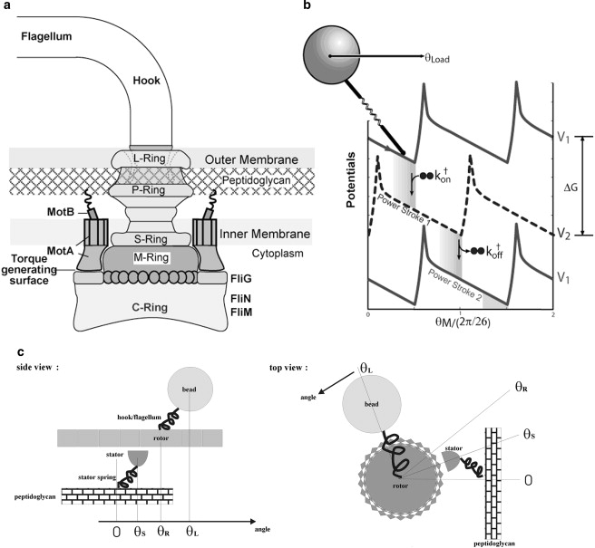
Schematic illustration of (a) the flagellar motor structure and (b) the mathematical model. There are three essential components in the model to reproduce the observed motor torque-speed relations: 1), a potential barrier to reduce futile backward slipping after a power stroke and to ensure tight coupling; 2), an elastic linkage between the motor and the bead; and 3), localized chemical transitions (reproduced from (25). with permission). (c) Definition of the angular variables θS, θR, and θL used in our simulations.
A schematic plot of the key components of the Escherichia coli bacterial flagellar motor (Fig. 1 a) has been derived from collected research of electron microscopy, sequencing, and mutational studies (reviewed in (7,8)). More recently, crystal structures of some of the rotor proteins have become available (7). The basal body comprises a rod connecting four protein rings, the L-ring, P-ring, MS-ring, and cytoplasmic C-ring (9). Functionally, the basal body is the rotor of the BFM. The rotor complex is homologous to the type III secretion system of Gram-negative bacteria (9,10). Around the periphery of the MS-ring, there is a circular array of stator complexes. They comprise the MotA and MotB proteins in a 4A2B stoichiometry. The MotA/MotB complex is homologous to the TonB-ExbB-ExbD and the TolA-TolQ-TolR complexes of outer membrane transport energizers (11,12). Both MotA and MotB span the cytoplasmic membrane. It is suggested that MotB anchors MotA to the rigid framework of the peptidoglycan through some 7- to 8-nm-long α-helices (the so-called stator springs in later discussions). MotA has four transmembrane α-helices and a large cytoplasmic loop. Mutational studies have found that several critical charged residues on this cytoplasmic loop interact electrostatically with charged residues on the C-terminus of FliG on the C-ring (13). This interaction is important for the torque generation mechanism of the BFM. FliG, FliM, and FliN constitute the C-ring and are also referred to as the “switch complex”, since mutations in this region often lead to defects in the switching function. The structure of the Na+ motor is similar to that of the H+ motor. The MotA/MotB complex correspondence is the PomA/PomB complex in the Na+ motor (14). The Na+ and H+ motors probably have the same mechanism. This idea is supported by the experimental observation that chimeric motors that mix components from both types of motor can still function (15). In the rest of this article, we will refer to one particular Na+-driven chimeric motor that uses a Na+-type stator and an E. coli BFM rotor (15). Since it is easier to change the Na+ concentration and sodium motive force (SMF) than the PMF and pH value in the medium without interfering with other cellular processes, this chimeric motor has become a favorable target in recent BFM studies (16–18).
To clarify the working mechanism of the flagellar motor, we need to understand the mechanochemical cycle of torque generation and how it is coupled to ion flux. In the past three decades, various experimental techniques have been implemented in the study of BFM. Before direct step measurement, the torque-speed relationship was the major biophysical probe to study the mechanism. By attaching a polystyrene bead onto the flagellum, or by applying rotating electric field, Berg and co-workers, followed by other researchers, measured how the motor torque (output of the motor) varies with speed (16,18–24). Those studies can be viewed as early experimental efforts of biophysics studies at single-protein/protein-complex levels. They give a full picture of the motor's output under external loads, and an indication of the energy conversion efficiency. The observed motor torque-speed relations, which show sharp transitions (the “knee”) between a plateau region at low speed and a steep concave-down region at high speed, remained unexplained for a long time (1).
In our previous article, we constructed a mathematical model to explain the observed motor torque-speed relationship (25). We showed that the flat plateau and knee are mainly due to 1), rotation being observed through a soft elastic linkage between the motor and the viscous load; and 2), the diffusion dynamics of the load and internal kinetics of the motor being on different timescales. Our model suggested that motor dynamics in the plateau region and in the concave-down region is controlled by thermodynamics and internal motor kinetics, respectively. Consequently, we suggested that the two components of the ion motive force, the membrane potential and the transmembrane ion gradient, are equivalent in controlling motor speed in the plateau region but may be nonequivalent in the concave-down region. The latest experiment by Lo et al. confirmed that individual components of the SMF show nonequivalent influence on the chimera motor function in the low load regime (26).
Our model also predicted that the motor speed at vanishing load (the zero-load speed) decreases with the number of stators. However, a recent experiment by Yuan and Berg showed that the zero-load speed is independent of the stator number (27). They performed numerical simulations with our model, and stated that the experimental result can be recovered if the stator springs, neglected in our original work, are explicitly treated and are sufficiently soft. However, this raises another concern about the model. One expects that a motor with soft stator springs will not show clear steps (28), yet Sowa et al. clearly observed 26 steps/revolution in a slow-rotating chimera motor. In this work, we examine whether our model is compatible with both the zero-load speed experiment and the stepping experiment. We focus on the dynamics of the flagellar motor. We first improve the modeling of ion hopping on/off rates in the model by explicitly considering extracellular/intracellular ion concentration. This modification allows separate treatment of the membrane potential and the ion gradient. We present results that can fit E. coli and chimera motor data, respectively. Models of the two types of motor are derived from the same framework but differ in the values of some parameters (e.g., ion hopping rates). Next, we show that the model predicts that the flagellar motor is a stepping motor, and we discuss the corresponding dwell-time distribution. After we introduce a soft stator spring in the model, the model reproduces both the stepping behavior and the correct zero-load speed dependence on the stator number. We further discuss the stepping behavior when two stators are engaged in the system. A series of testable predictions are made, which will become the starting point of a new generation of experiments.
Model Formation and Computational Details
Detailed information about the motor has been accumulated via extensive biochemical, cryoelectron microscopy, crystallography, and mutational studies. Current biochemical and structural studies imply that the motor torque is generated by stator conformational changes upon ion binding/unbinding to the negatively charged D32 residue on the MotB helices (D24 on PomB for the Na+ motor). This motion is transmitted to the rotor via interactions at the rotor-stator interfaces (see (1,7) and references therein). Details of these interactions will remain vague until the atomic structure of the stator has been determined; currently the structures of but a few portions of the rotor are available (29–31).
Our coarse-grained model integrates available information from various experimental observations (25). To generate sufficient torque, we assume that one torque generation cycle of the stator is driven by the free energy derived from transporting two periplasmic protons to the two negatively charged D32 residues on the two MotB helices, then to the cytoplasm. On binding and releasing the ions, two cytoplasmic MotA loops alternate in contacting successive FliGs on the rotor, like two alternating “pistons”. The MotA loop motions result in a downward stroke followed by a recovery stroke, each of which pushes the rotor to rotate. During the cycle, the stator is always engaged with the rotor; i.e., the duty ratio is 1. The binding energy of the protons to MotB is converted into a “flashing” electric field in the stator that triggers a pair of conformational transitions (Fig. 1 b). The torque thus generated is transmitted to the rotor when the MotA loops are in contact with the FliGs. The interaction between MotA and FliG is most likely (but not necessarily) dominated by electrostatic and steric interactions (13,25). Detailed modeling of these interactions has to wait for more structural information.
The above process can be described mathematically by a set of stochastic equations. The dynamics of the single stator motor pulling a viscous load via an elastic linkage can be described by the Langevin equation
| (2) |
where the angles θS,θR, and θL are defined in Fig. 1 c, and θS is set to zero except in simulations that consider stator spring explicitly. ζR is the effective drag coefficient of the rotor. The viscous load (e.g., the polystyrene bead) is coupled to the rotor via an elastic linkage, which is modeled by a harmonic potential, VRL = 1/2κ(θR − θL)2. The last term is the stochastic Brownian force acting on the rotor, where ƒR(t) is uncorrelated white noise with normal Gaussian distribution (32,33). VRS is the potential of mean force of the rotor-stator interaction, and s is a binary variable referring to the stator conformational state: right or left piston down. The potentials VRS are chosen as identical periodic free energy profiles, each offset by a half-period, as shown in Fig. 1 b. The choices of the potential shapes and the exact half-period offset here are for simplicity, and can be improved when more structural and dynamic information is available. Our numerical studies have shown that our conclusion does not depend upon the exact shape of the potentials. The slope of VRS determines the force profile the stator exerts on the rotor. The high peak at the top of each potential ensures tight coupling between the rotor and stator by preventing a thermal fluctuation from carrying the system to the left (backward slipping) and “wasting” a pair of translocated protons. The structural correspondence of the barrier needs further study. We suggest that steric interactions between FliGs and the cytoplasmic loop of MotA may contribute to the barrier. In parallel to the motor spatial motion, a stator can switch between the two stator chemical states, which correspond to the two potential curves shown in Fig. 1 b. The switching is described by Kramers jump processes between the two potential curves. The Kramers rates are directly related to the ion motive force (IMF). In our original model, the effect of IMF was described by a composite factor. To study the effect of the two components (ion concentration gradient and transmembrane potential) separately, in this work we model the jump rates for the exchange of two ions between the periplasm and stator binding sites as
| (3) |
and
| (4) |
and those between the cytoplasm and a stator binding site as
| (5) |
and
| (6) |
where the functions V1 and V2 refer to the potentials VRS for the two stator states (empty and occupied, respectively); Cperi and Ccyto are the ion concentrations at the periplasmic and cytoplasmic sides, respectively, in mM; pKa is the intrinsic dissociation constant of the ion binding site along the stator channel; and k0 is a prefactor of the transition rates. The function f (θ, α, β) is the transition window accounting for the requirement that chemical transitions and the rotor position are coupled (see (25) for details). Here, we use a triangle shape:
| (7) |
or a uniform function
| (8) |
In each torque generation cycle, two ions from the periplasm jump onto a stator and are later released to the cytoplasm. The rotor rotates an average angle of 2π/26, and the free energy of the overall systems drops Therefore, in the above rate expressions, detailed balance is automatically satisfied. For simplicity, we assume that ion binding is cooperative and not saturated. Notice that the two components of the ion motive force affect the jump rates differently. The ion concentrations affect only the on rates. The effect of the membrane potential is more complicated, either occurring indirectly, through increasing local ion concentrations at the membrane surface, or directly, via the transition dynamics. Here, for simplicity, we assume that the on and off rates for a particular jump are equally affected by the membrane potential. The parameter γ specifies the partition of membrane potential for the two half steps of the torque generation cycle. We found a γ-value of ∼0.6 gives the best fit to the results of Lo et al. (26). This result is consistent with the structural fact that the residue D32 resides close to the cytoplasmic end of the membrane, and thus one expects a larger effect of the membrane potential on the ion hopping rates from the periplasmic side.
The next step in our model is to include the load, e.g., the latex bead attached to the flagellum. Simultaneously, the motion of the load is described by the Langevin equation
| (9) |
Here, the elastic coupling term appears with a sign opposite that in Eq. 2, and ζL is the drag coefficient of the load. The last term is the Brownian force on the load. The characteristic timescale for the motion of the load is tL = ζL/κ.
In the case with rigid connection between the stator and the peptidoglycan, the model equations (Eqs. 2 and 9) can be replaced by the equivalent coupled Fokker-Planck equations with θS = 0, describing the probability density, ρj (θL, θR, t) of the rotor and load being at position (θL, θR) and chemical state j at time t while driven by a single stator:
| (10) |
Here, DR and DL are the diffusion constants of the rotor and the bead, respectively, related to the drag coefficients by the Einstein relation ζ = kBT/D. We solved the steady state of the Fokker-Planck equations with the algorithm developed by Xing et al. (34). The algorithm discretizes the conformational coordinates and transforms the partial differential equations into a jumping process over many discrete states with their normalized populations, p (defined as the probability density integrated over the discrete regions) described in the form Kp = 0. The composite K matrix contains transitions along both the conformational and reaction coordinates (see (35) for details). The steady-state motor rotation rate is obtained by calculating the spatial flux (summing over all the chemical states) at one spatial point. We also performed Langevin dynamics simulations with one or two stators engaged to obtain single-motor trajectories.
More degrees of freedom need to be included if we consider the stator fluctuations. Structural studies show that the stators are fixed to the peptidoglycan through elastic linkages (2,36). In our previous study, we neglected the stator fluctuations for mathematical simplicity. Recent experiments by the Berg group revealed that stator fluctuations give rise to some new dynamic behaviors in the low-load region (27). Their results contradict a prediction of our original model (25). These researchers showed that the experimental results can be reproduced if the stator springs are included in our model. In some results presented here, we modeled the stator linkages by harmonic springs and allowed the stators to fluctuate around their equilibrium position. The movement of each stator can be described by an additional Langevin equation similar to Eqs. 2 and 9:
| (11) |
where θSi, θ0i, and Si are the position, equilibrium position, and ion occupation state of the ith stator. When there are N stators functioning in the system, the torque applied to the rotor is a sum of the interaction potentials induced by each individual stator at a different position and with different ion binding status. In a corresponding way, the rotor-stator interaction term in Eq. 2 becomes:
| (12) |
The complete BFM model with stator springs explicitly treated is solved by the Langevin simulation approach. In these simulations, we implemented parallel Monte Carlo processes, to simulate the motion of the rotor, stators, and bead driven by model potentials and to determine the ion hopping on/off in each stator. The motor speed is obtained by running a very long time simulation and dividing the final displacement by the total simulation time. In our current model, stators interact indirectly with each other by working against a common rotor. Langevin simulations are also used to study the stepping behavior of the motor. The stepping statistics (e.g., step size and dwell-time distribution) are collected by a step-finder program, described previously (37). The same program was used earlier to analyze the BFM stepping data (17).
Results
Torque-speed relationship and effects of different energy components
First, we reproduce the E. coli BFM torque-speed curve with the new jumping rate formulation. Under normal living conditions, the E. coli BFM functions at intracellular pH 7.6, external pH 7, and membrane potential 120 mV. Without modifying the potential profiles, the E. coli BFM torque-speed curve can be easily reproduced by inputting these realistic values into our new formulation (Fig. 2 a). Model parameters are given in Table 1.
Figure 2.
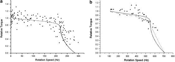
Experimental (triangles) and calculated (solid lines) torque-speed curves for (a) the E. coli H+ and (b) the chimera BFM motors. Normalized torque is used in both figures. In b, we show two model predictions, where the solid line describes the same transition-assisting window as used in E. coli fitting, and the dashed line describes a uniform transition window.
Table 1.
Model parameters
| Quantity | Value | Comments | |
|---|---|---|---|
| Potential periodicity, δ | 2π/26 | See (7,17). | |
| Rotor drag coefficient, ζR | 2 × 10⁻³ pN·nm·s/rad2 | Estimated | |
| Bead diffusion constant, DL | 0.01–100 rad2/s | Calculated from Stokes' Law | |
| Stator diffusion constant, Ds | 500 rad2/s | Estimated | |
| Load-rotor linkage spring constant, κ | 400–500 pN·nm/rad2 | Estimated from experimental measurements (49) | |
| Saw-tooth potential height, U | 10 kBT | Ad hoc | |
| Ratio of the two potential branches, Lleft/Lright | 1/9 | ||
| Potential bumps | Height | 15 kBT | |
| Width | 0.2δ | ||
| Centers | 0.1δ (State1) | ||
| 0.6δ (State 2) | |||
| Transition windows | α1, α2 | 0.1δ, 0.6δ | Fitting data |
| β1β2 | 0.58δ, (0.58 + 0.5)δ | ||
| Binding site pK value | H+ motor | pKa= 7.3 | Estimated (using the middle value of external and internal concentrations) |
| Chimera motor | pKa= 31.6 mM | ||
| Binding rate prefactors (two ions) k0 | H+ motor | 1.0 × 10²⁰ s−1 | Fit experimental torque-speed curve |
| Chimera motor | 1.0 × 10⁸ s−1 (or 6.0 × 10⁷ s−1 with a uniform window) | ||
| E. coli BFM living condition | pHperiplasm | 7.0 | Experimental values |
| pHcytoplasm | 7.6 | ||
| Vmembrane | 120 mV | ||
| Chimera BFM living condition | [Na]periplasm | 85 mM | |
| [Na]cytoplasm | 12 mM | ||
| Vmembrane | 140 mV |
The chimera motor uses a Na+ type BFM stator and H+ type BFM rotor. The torque-speed relationship of the chimera motor has been reported by Inoue et al. (18). It is highly similar to that of the E. coli BFM except for a higher “knee” speed and zero-load speed. Without changing the driving potential profiles, we substitute the experimental values of the chimera-motor living condition into our model and fit the chimera torque-speed curve. In Fig. 2 b, we present two model results, one with the same chemical transition window as that of the E. coli motor and the other with a uniform window. Because the torque-speed curves can be reproduced (on both E. coli and chimera) with the same model framework, there is likely no fundamental distinction in the energy transduction mechanism between E. coli and chimera motors. The difference in the detailed shapes of the motor torque-speed relations may reflect subtle structural differences. We model the difference by the transition window shape, which reflects the coupling between stator ion transduction and the relative positions of rotor and stator.
Our model gives an explicit answer to the mysterious BFM torque-speed relationship. At high load, the bead response time is much longer than the motor internal (ion hopping on/off and rotor motion) dynamics. The motor dynamics is near equilibrium under external constraint (from the load). The motor torque is determined by thermodynamics (25,38–40).
| (13) |
where ωL is the angular velocity of the load, δ = 2π/26 is the angular step length (i.e., the distance between FliGs), and ΔG is the free energy drop per stator cycle derived from IMF(PMF or SMF). However, at low load, there is no timescale separation between the bead relaxation and the internal motor processes, and the motor dynamics is kinetics-controlled. The observed transition between the plateau and knee region is quite sharp. As discussed in our previous article, this observation can be explained by the interplay between localized transitions along θR and stator mutual interference. To make a transition from one potential curve to another (corresponding to ion hopping on and off within one stator), the rotor needs to rotate into the transition window. However, other stators may push the rotator to move out of the transition window before the chemical transition takes place. Consequently, the rotor is trapped until thermal fluctuations bring it back into the transition window so that the stator can switch its chemical state. A load reduces occurrence of the trap by pulling the rotor backward. Therefore, decreasing the load shortens the bead response time and lengthens the motor internal dynamics at the same time. This results in abrupt change of the system from the thermodynamics-controlled plateau region (with timescale separation between the bead response time and the motor internal kinetics) to the kinetics-controlled knee region (with no timescale separation between them).
A direct prediction of the above discussion is that the two components of the ion motive force, the concentration gradient and the transmembrane potential, are equivalent in the high-load region, but may not necessarily be equivalent in the low-load region. Fig. 3 a shows that the motor speed is proportional to the membrane voltage in both directions. This result is consistent with Berg's experiment (22,23). However, as shown in Fig. 3 b, the motor speed responds to periplasmic ion concentrations asymmetrically, and becomes saturated at high ion concentrations, consistent with experimental observations (16).
Figure 3.
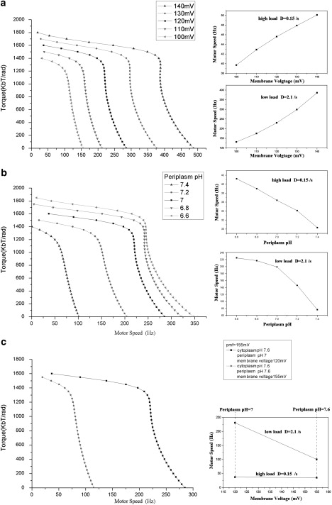
Different effects of the two energy components on E. coli motor dynamics. (a) Effect with fixed ion concentrations but varying membrane potential, showing motor speed versus membrane voltage along a high-load (D = 0.15 rad2/s) line (upper inset) and along a low-load (D = 2.1 rad2/s) line. (b) Effect with fixed membrane potential but varying external ion concentration, showing motor speed versus periplasm pH along a high-load (D = 0.15 rad2/s) line (upper inset) and along a low-load (D = 2.1 rad2/s) line (lower inset). (c) Effect with fixed IMF but different portions of membrane potential and ion concentration difference, comparing the motor speed at high load and low load with fixed IMF. Here we show results for the H+ motor. Similar results are obtained for the chimera motor.
Using our model, we can also investigate the effect of varying the relative ion concentration and membrane potential contributions while holding the total IMF constant. Fig. 3 c shows that the external ion concentration has a much stronger influence on the motor output. The motor speed decreases dramatically when the external ion concentration is lowered, despite the total IMF being compensated by a transmembrane voltage increase. Fig. 3 c compares our simulations with the experimental observations of Lo et al. (26). Therefore, our model correctly predicts that the motor speed depends more strongly on the external ion concentration than on the membrane voltage. One obvious explanation is that the diffusion-limited binding of ions is the rate-limiting step at low load, but not at high load.
Zero-load speeds and the stator springs
Our original model predicted that the motor zero-load speed (i.e., the rotation speed without external load) decreases with the number of stators engaged, a remnant of the stator mutual interference effect discussed above (25). Recently, Yuan and Berg tested this prediction in a proton-driven motor (27). Their observations show that the zero-load speeds with different numbers of stators converge to a single value. This result suggests that the mutual interference between stators is not as strong as we suggested near the zero-load regime. This can be explained by the fact that MotB in each stator is linked to the peptidoglycan through α-helices several nanometers long. The linker may introduce compliance and allow lateral fluctuation of the stator. In our original model, we neglected such stator fluctuations due to the stator springs. Yuan and Berg performed numerical simulations using our model, and found that a converged zero-load speed can be obtained by introducing soft stator springs. With the stator springs, the above-mentioned destructive interference among stators at high speed is reduced (see Fig. 7 c). We performed similar simulations (Fig. 4) and found that a spring stiffness constant of ∼200 pN · nm/rad2 is sufficient to reasonably reproduce the experimental data. The angular spring constant corresponds to a translational spring constant of 1 pN/nm if we assume the rotor radius is 15 nm. This value agrees well with the estimated linker stiffness when it is assumed to be an α-helix and with the value determined by Yuan and Berg (27).
Figure 7.
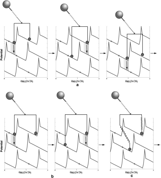
Stepping behaviors with two stators. (a) With stiff stator springs, the motor may generate substeps that reflect the distance between the two stators, ΔθS, relative to the rotor periodicity, δ. If the ratio ΔθS/δ is not integer, smaller substeps may be observed. (b) If the ratio ΔθS/δ is integer, the stepsize is the same as in the case of one stator, but the dwell time is longer on average. (c) With soft stator springs, chemical transition within one stator is not restricted by the other stator.
Figure 4.
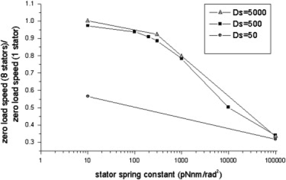
Zero-load speed of an eight-stator E. coli motor compared to the zero-load speed of a one-stator motor with a different stator spring constant (different lines are obtained with different stator diffusion constants).
The motor is a stepper
As discussed above, the zero-load speed results require lateral fluctuations of the stators. However, existence of soft stator springs can smear the steps in a motor trajectory (28). On the other hand, steps have been observed experimentally for the chimera motor. Can our model reproduce both sets of experiments? Below, we show some model simulation results following experimental conditions and the methods used to analyze the experimental data.
Similar to the experimental procedure, in our simulation we assign Nstator = 1 and lower the external sodium concentration. Stepping behavior becomes obvious when the motor speed is <10 Hz. In Fig. 5 a, we show a series of stepping traces under various external sodium concentrations. Note that in the experimental traces (Fig. 5 b) published by Sowa et al., the information of the external sodium concentration is lacking. By comparing the experimental traces with our simulation, we can make an educated guess about the external sodium concentration of the cells studied in these experiments. For example, the central three traces running at 0.5 ∼ 2 Hz are from an environment with ∼0.5 ∼ 1.5 mM external sodium concentration. If the external sodium concentration is <0.5 mM, backward steps occur frequently, and the motor cannot make noticeable advancement.
Figure 5.
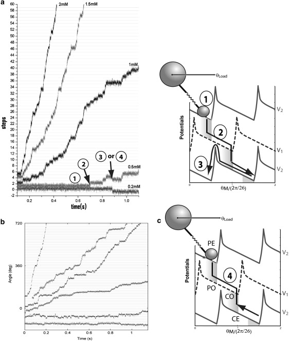
Single-molecule trajectories of the chimera motor at different external Na+ concentrations. (a) Simulations. (b) Experimental data from Sowa et al. (17). (c) Schematic illustration of the stepping behavior. The labels in a and c are consistent: 1, local fluctuation within a potential well; 2, fast transient sliding along a potential after chemical transition; 3, backward slipping that breaks tight coupling; and 4, backward motion with tight coupling between motor motion and chemical transitions. To make easy connection between the continuous model and other discrete kinetic models (e.g., (50)), we referred to the corresponding motor mechanochemical states as “PE”, “PO”, “CE”, and “CO”, where “P” and “C” mean that the ion binding sites are accessible from the periplasm and cytoplasm sides, respectively, and “E” and “O” mean the binding sites are empty and occupied, respectively.
It remains to be confirmed whether steps can be resolved in wild-type E. coli motors as in chimera motors. Next we theoretically explore the conditions under which E. coli motor stepping can be seen. The speed of the motor decreases rapidly when the external pH value is increased. However, in real experiments, the E. coli cells are not able to endure a large pH change, since they cannot survive a strongly alkaline environment. Therefore, our aim is to find the least demanding condition under which steps can be resolved. Fig. 6 a shows simulated results with external pH = 8.4 and internal pH = 7.6. Two stator spring constants are used. One is κ = 200 pN nm/rad2, the value used above to reproduce the zero-load speeds; the other is κ = 3000 pN nm/rad2. We suggest that the spring constant could be stiffened, e.g., through antibody binding onto the stator linker or use of a mutant with a shorter and thus presumably stiffer linker. The motor runs at ∼8 Hz, with detectable steps in both cases, although the trajectory with the softer stator spring is noisier. Fig. 6 b shows the step-size distribution obtained with the step-finder algorithm used previously (37). The step-size distribution is centered around 26 steps/revolution, consistent with the experimental results of Sowa et al. (17) for the chimera motor. In our model, each motor cycle has two half-steps. However, under the experimental conditions simulated in Fig. 6 b, only the ion binding from the periplasm is rate-limiting: the second half-step, corresponding to release of two ions into the cytoplasm, follows the first half-step too rapidly to be resolved. Our model suggests that clear substeps may be observed if the ion binding sites (D32) have higher ion binding affinity than those of the wild-type, and thus a lower ion off rate. Fig. 6 c shows the corresponding dwell-time distributions. It can be fitted with a single-exponential decay. These results are similar to those of recent higher-resolution experiments in R. M. Berry's lab.
Figure 6.
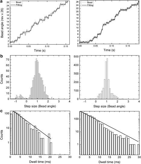
Predicted E. coli BFM stepping behavior for one stator with stator spring constants κ = 200 pN nm/rad2 (left panels) and κ = 3000 pN nm/rad2 (right panels) by analyzing 10-s-long trajectories. Parameters are the same as in Table 1, except for pHperiplasm = 8.4. (a) A typical trajectory (solid lines are steps found by the step-finding algorithm); (b) The stepping size distribution. (c) The stepping dwell-time distribution.
To conclude, our model reproduces the chimera motor stepping, and predicts the conditions under which E. coli motor stepping should be observable, and the corresponding statistics. Experimental realization of these conditions is on the way.
The motion of a protein motor is continuous for all biological purposes. Why does the continuous motion of the motor result in stepping behavior? Stepping behavior has been observed for many protein motors (41,42). Fig. 5 c shows schematically how the continuous motion of a protein motor produces steps. For most of the time, the motor fluctuates around a potential minimum, so one observes the motor (or the indicator) to fluctuate around a fixed angular (or spatial) position (Fig. 5 c, 1). The distribution of the motor position reveals the local structure of the potential well. After a chemical transition takes place, the motor slides down a new potential until it reaches the next potential minimum. Experimentally, one observes fast motion of the motor (Fig. 5 c, 2) and then fluctuation around the new minimum. The relatively fast transient motion and long time dwelling around some positions give the stepping behavior of the motor, and this justifies usage of discrete kinetic models for modeling protein motors (43).
Occasionally, backward steps can be observed. Two possible transitions can result in backward motion. The motor, with the ion binding sites empty or occupied, may simply slip backward over the potential barrier (Fig. 5 c, 3), in which case ions are translocated without net motor motion, and the two motions are thus decoupled. The backward step could also be the inverse of the process described by step 2 (Fig. 5 c, 4), in which a motor rests in a state with empty stator binding sites and angular positions such that ions are accessible to the binding sites from the periplasmic side (the “PE” state in a discrete kinetic model). Random thermal fluctuations allow the motor to rotate to the angular locations at which the stator binding sites are accessible from the cytoplasmic side (the “CE” state). Then the motor picks up a pair of ions (the “CO” state), fluctuates back (CO → PO), and releases ions to the periplasmic side (PO → PE). In this case, the motor motion and the chemical transition are still tightly coupled. The BFM functions as a pump when this type of backward step takes place. One difference between these two mechanisms is that the loose-coupling mechanism produces a full backward step only, but the tight coupling mechanism can in principle produce half-steps. The backward substeps, if they exist, may also be resolved if a mutant is used in which the stators have high ion binding affinity, so that the step of releasing the binding ions to the periplasm can be slowed down. Decreasing the extracellular ion concentration has less effect on the loose-coupling mechanism than on the tight-coupling mechanism. For the latter, a longer waiting time for the motor to pick up ions from the periplasm increases the probability that the motor will instead pick up ions from the cytoplasm, and thus a backward step takes place. It is experimentally observed that the number of backward steps increases when the extracellular ion concentration is decreased. This suggests that the tight-coupling backward mechanism contributes to the observed backward steps. However, we cannot rule out the loose-coupling mechanism. We want to point out that description of backward motion is automatically included in a potential-based continuous model (35).
Step size versus stator number
In this section, we discuss the stepping behavior for a motor with multiple stators engaged. Fluctuation analysis predicted that the step size decreases to 1/n of δ if there are n stators in the system (44,45). However, a recent experiment on the chimera motor reveals “the apparent independence of step size on stator number” (17). These two results obviously contradict each other.
In stator resurrection experiments using the chimeric motor, one decreases the external ion concentration to disengage the stators from the rotor, then waits for the stators to resurrect, i.e., reengage one by one in random sequence (17). Therefore, the relative distance between the two resurrecting stators may be different in different experimental attempts. Because our model potentials are 2π/26 periodic, we can project all the stator positions into one period, δ = 2π/26. The projection allows us to visualize the relative phase of these stator positions. For simplicity here, we discuss only Nstator = 2. Taking the first stator as the reference point, the second stator can be bound at any position ΔθS ∈ (0, δ). Fig. 7 gives a qualitative picture of the stepping behavior of a motor with two stators based on our model framework. Fig. 7, a and b, shows two cases with stiff stator springs but different ratios of the stator distance, ΔθS, over the rotor periodicity δ (2π/26). If the ratio is not integer, one expects doubled step numbers and smaller step sizes reflecting ΔθS/δ compared to the one-stator case. If the ratio is integer, around each dwelling configuration (one local minimum of the composite potential) the system cannot move forward until both the stators change their chemical states. Consequently, the step numbers and size are the same as in the one-stator case, but with a longer dwell time on average. With soft stator springs, the spatial mutual coupling between the chemical transitions within the stators is reduced (Fig. 7 c). The above discussed difference with different ΔθS/δ may be less clear. Fig. 8 shows the step-size distributions calculated from simulated traces by the step finder with different values of the stator spring stiffness and ΔθS/δ. With stiff stator springs, and ΔθS/δ = 0.5 or 1, the step sizes are indeed centered around 0.5δ and δ, respectively (with a longer average dwell time for the latter; results not shown). With soft stator springs, on the other hand, in both cases, the step sizes show broad distributions centered around δ. The soft stator spring results may explain why the observed step sizes are apparently independent of stator number. The fluctuation analysis of Samuel and Berg (44) counts the number of statistically independent rate-limiting events, which is not necessarily the same as the number of observable mechanical steps.
Figure 8.
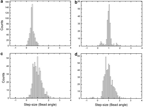
E. coli BFM step-size distributions with two stators predicted by analyzing 2-s-long trajectories with a step-finding algorithm. (a) Two stators offset by 0.5δ, stator spring κ = 3000 pN nm/rad2. (b) Two stators offset by δ, stator spring κ = 3000 pN nm/rad2. (c) Two stators offset by 0.5δ, stator spring κ = 200 pN nm/rad2. (d) Two stators offset by δ, stator spring κ = 200 pN nm/rad2.
Discussion and Conclusions
Our model is a work in progress, which can be refined in several aspects in response to future experimental results:
First, in our original model, the stator effect is partly absorbed in the model parameters (parameter renormalization). With explicit treatment of the stator springs, the model needs to be reparameterized. Our numerical studies found that the generic behaviors of the torque-speed curves, i.e., the existence of plateau and linear ion motive force dependence of the rotation speed at the low-speed region, and decline of the motor torque at the high-speed region, are to a large extent insensitive to model parameters (see also Fig. 4). As explained in the original article, they are a general consequence of the interplay of several timescales in the system. On the other hand, detailed shapes of the torque-speed curves do depend on some model parameters. The stator springs greatly expand the degrees of freedom in the model. An efficient numerical method is needed for fast parameter optimization in the future.
Second, the model discussed in the original article and in this work is rather generic. Some details relevant to the motor function may be missing. At present, we assign all the stator-stator interactions through a common rotor. The neighboring stators may interact directly as well as through the rotor. A similar idea has been proposed for the F1 part of the ATP synthase (46). For the flagellar motor, electron microscopic images show that the arrangement of stators is crowded (47). A stator under tension distorts the membrane as well as the stator springs. The stators may interact with each other through tension-dependent membrane-mediated interactions (48). This lateral coupling may ensure that there is sufficient destructive stator mutual interference to produce the sharp transition of the motor torque-speed curves, and that the mutual interference drops on decreasing the load to produce the correct zero-load speed behavior.
Third, in our model, we enforce the tight coupling assumption by high potential barriers. This assumption means that there is a definite coupling between rotor rotation and the number of ions transferred: one step (∼2π/26) of forward rotation of the rotor accompanies transfer of two ions from the periplasm to the cytoplasm; one step of backward rotation of the rotor accompanies transfer of ions from the cytoplasm to the periplasm (therefore, the BFM acts as a pump). We made this assumption because several experimental results are in agreement with the consequences when the motor is tightly coupled. However, none of the existing experimental evidence really precludes the possibility that the motor is not perfectly coupled (i.e., near 100%). To clarify this problem, we require an accurate measurement of the stall torque and the corresponding stepping statistics in single-stator motors at both high and low load. Then, the exact number of ions consumed in a motor step can be calculated. Furthermore, if one can measure and control the ion flux through the stator channel, the answer to the above “coupling” puzzle will be straightforward.
In summary, we analyzed the dynamics of our BFM model in detail. The model predicts the observed nonequivalence of the two components of the ion motive force at high-speed regions. With explicit consideration of the stator springs, the model reproduces the observed zero-load speed dependence on stator numbers. The motor can be a stepper even in the presence of stator springs. With two stators engaged, however, smaller steps are difficult to resolve. We suggest that if the stator springs can be stiffened (e.g., through antibody binding), more insights into the BFM dynamical behaviors can be obtained. We also suggest that substeps (for both forward and backward steps) may be resolved if one uses a mutant with stator charges that have higher affinity for the binding ions than do the stator charges of the wild-type.
Acknowledgments
F.B. is supported by the Wellcome Trust VIP research funding. C.-J.L thanks the Swire Group/ORS for financial support. J.X. was initially supported by a Lawrence Livermore National Laboratory Directed Research and Development grant. This work was partly performed under the auspices of the U.S. Department of Energy by the University of California, Lawrence Livermore National Laboratory, under contract No. W-7405-Eng-48.
References
- 1.Berg H.C. The rotary motor of bacterial flagella. Annu. Rev. Biochem. 2003;72:19–54. doi: 10.1146/annurev.biochem.72.121801.161737. [DOI] [PubMed] [Google Scholar]
- 2.Blair D.F., Kim D.Y., Berg H.C. Mutant MotB proteins in Escherichia coli. J. Bacteriol. 1991;173:4049–4055. doi: 10.1128/jb.173.13.4049-4055.1991. [DOI] [PMC free article] [PubMed] [Google Scholar]
- 3.Berg H.C. The bacterial rotary motor. In: Hackney D.D., Tamanoi F., editors. The Enzymes, Vol. 23. Energy Coupling and Molecular Motors. Academic Press; New York: 2003. pp. 143–202. [Google Scholar]
- 4.Berry R. The bacterial flagellar motor. In: Belushkin A., editor. Forces, Growth and Form in Soft Condensed Matter: At the Interface between Physics and Biology. Kluwer Academic; Dordrecht, The Netherlands: 2004. pp. 145–164. [Google Scholar]
- 5.Berg H.C. Dynamic properties of bacterial flagellar motors. Nature. 1974;249:77–79. doi: 10.1038/249077a0. [DOI] [PubMed] [Google Scholar]
- 6.Reid S.W., Leake M.C., Chandler J.H., Lo C.J., Armitage J.P. The maximum number of torque-generating units in the flagellar motor of Escherichia coli is at least 11. Proc. Natl. Acad. Sci. USA. 2006;103:8066–8071. doi: 10.1073/pnas.0509932103. [DOI] [PMC free article] [PubMed] [Google Scholar]
- 7.Blair D.F. Flagellar movement driven by proton translocation. FEBS Lett. 2003;545:86–95. doi: 10.1016/s0014-5793(03)00397-1. [DOI] [PubMed] [Google Scholar]
- 8.Sowa Y., Berry R.M. Bacterial flagellar motor. Q. Rev. Biophys. 2008;41:103–132. doi: 10.1017/S0033583508004691. [DOI] [PubMed] [Google Scholar]
- 9.Thomas D.R., Francis N.R., Xu C., DeRosier D.J. The three-dimensional structure of the flagellar rotor from a clockwise-locked mutant of Salmonella enterica serovar Typhimurium. J. Bacteriol. 2006;188:7039–7048. doi: 10.1128/JB.00552-06. [DOI] [PMC free article] [PubMed] [Google Scholar]
- 10.Marlovits T.C., Kubori T., Sukhan A., Thomas D.R., Galan J.E. Structural insights into the assembly of the type III secretion needle complex. Science. 2004;306:1040–1042. doi: 10.1126/science.1102610. [DOI] [PMC free article] [PubMed] [Google Scholar]
- 11.Zhai Y.F., Heijne W., Saier J., Milton H. Molecular modeling of the bacterial outer membrane receptor energizer, ExbBD/TonB, based on homology with the flagellar motor, MotAB. Biochim. Biophys. Acta. 2003;1614:201–210. doi: 10.1016/s0005-2736(03)00176-7. [DOI] [PubMed] [Google Scholar]
- 12.Cascales E., Lloubes R., Sturgis J.N. The TolQ-TolR proteins energize TolA and share homologies with the flagellar motor proteins MotA-MotB. Mol. Microbiol. 2001;42:795–807. doi: 10.1046/j.1365-2958.2001.02673.x. [DOI] [PubMed] [Google Scholar]
- 13.Zhou J., Lloyd S.A., Blair D.F. Electrostatic interactions between rotor and stator in the bacterial flagellar motor. Proc. Natl. Acad. Sci. USA. 1998;95:6436–6441. doi: 10.1073/pnas.95.11.6436. [DOI] [PMC free article] [PubMed] [Google Scholar]
- 14.Yorimitsu T., Homma M. Na+-driven flagellar motor of Vibrio. Biochim. Biophys. Acta. 2001;1505:82–93. doi: 10.1016/s0005-2728(00)00279-6. [DOI] [PubMed] [Google Scholar]
- 15.Asai Y., Kawagishi I., Sockett R.E., Homma M. Hybrid motor with H+- and Na+-driven components can rotate Vibrio polar flagella by using sodium ions. J. Bacteriol. 1999;181:6332–6338. doi: 10.1128/jb.181.20.6332-6338.1999. [DOI] [PMC free article] [PubMed] [Google Scholar]
- 16.Sowa Y., Hotta H., Homma M., Ishijima A. Torque-speed relationship of the Na+-driven flagellar motor of Vibrio alginolyticus. J. Mol. Biol. 2003;327:1043–1051. doi: 10.1016/s0022-2836(03)00176-1. [DOI] [PubMed] [Google Scholar]
- 17.Sowa Y., Rowe A.D., Leake M.C., Yakushi T., Homma M. Direct observation of steps in rotation of the bacterial flagellar motor. Nature. 2005;437:916–919. doi: 10.1038/nature04003. [DOI] [PubMed] [Google Scholar]
- 18.Inoue Y., Lo C.-J., Fukuoka H., Takahashi H., Sowa Y. Torque-speed relationships of Na+-driven chimeric flagellar motors in Escherichia coli. J. Mol. Biol. 2008;376:1251–1259. doi: 10.1016/j.jmb.2007.12.023. [DOI] [PubMed] [Google Scholar]
- 19.Chen X., Berg H.C. Solvent-isotope and pH effects on flagellar rotation in Escherichia coli. Biophys. J. 2000;78:2280–2284. doi: 10.1016/S0006-3495(00)76774-9. [DOI] [PMC free article] [PubMed] [Google Scholar]
- 20.Berg H.C., Turner L. Torque generated by the flagellar motor of Escherichia coli. Biophys. J. 1993;65:2201–2216. doi: 10.1016/S0006-3495(93)81278-5. [DOI] [PMC free article] [PubMed] [Google Scholar]
- 21.Ryu W., Berry R., Berg H. Torque-generating units of the flagellar motor of Escherichia coli have a high duty ratio. Nature. 2000;403:444–447. doi: 10.1038/35000233. [DOI] [PubMed] [Google Scholar]
- 22.Gabel C.V., Berg H.C. The speed of the flagellar rotary motor of Escherichia coli varies linearly with proton motive force. Proc. Natl. Acad. Sci. USA. 2003;100:8748–8751. doi: 10.1073/pnas.1533395100. [DOI] [PMC free article] [PubMed] [Google Scholar]
- 23.Fung D., Berg H.C. Powering the flagellar motor of Escherichia coli with an external voltage source. Nature. 1995;375:809–812. doi: 10.1038/375809a0. [DOI] [PubMed] [Google Scholar]
- 24.Chen X., Berg H.C. Torque-speed relationship of the flagellar rotary motor of Escherichia coli. Biophys. J. 2000;78:1036–1041. doi: 10.1016/S0006-3495(00)76662-8. [DOI] [PMC free article] [PubMed] [Google Scholar]
- 25.Xing J., Bai F., Berry R., Oster G. Torque-speed relationship for the bacterial flagellar motor. Proc. Natl. Acad. Sci. USA. 2006;103:1260–1265. doi: 10.1073/pnas.0507959103. [DOI] [PMC free article] [PubMed] [Google Scholar]
- 26.Lo C.-J., Leake M.C., Pilizota T., Berry R.M. Nonequivalence of membrane voltage and ion-gradient as driving forces for the bacterial flagellar motor at low load. Biophys. J. 2007;93:294–302. doi: 10.1529/biophysj.106.095265. [DOI] [PMC free article] [PubMed] [Google Scholar]
- 27.Yuan J., Berg H.C. Resurrection of the flagellar rotary motor near zero load. Proc. Natl. Acad. Sci. USA. 2008;105:1182–1185. doi: 10.1073/pnas.0711539105. [DOI] [PMC free article] [PubMed] [Google Scholar]
- 28.Walz D., Caplan S.R. A kinetic and stochastic analysis of crossbridge-type stepping mechanisms in rotary molecular motors. Biophys. J. 2005;89:1650–1656. doi: 10.1529/biophysj.105.060095. [DOI] [PMC free article] [PubMed] [Google Scholar]
- 29.Lloyd S., Whitby F., Blair D., Hill C. Structure of the C-terminal domain of FliG, a component of the rotor in the bacterial flagellar motor. Nature. 1999;400:472–475. doi: 10.1038/22794. [DOI] [PubMed] [Google Scholar]
- 30.Brown P., Hill C., Blair D.F. Crystal structure of the middle and C-terminal domains of the flagellar rotor protein FliG. EMBO J. 2002;21:3225–3234. doi: 10.1093/emboj/cdf332. [DOI] [PMC free article] [PubMed] [Google Scholar]
- 31.Brown P., Mathews M., Joss L., Hill C., Blair D.F. Crystal structure of the flagellar rotor protein FliN from Thermotoga maritima. J. Bacteriol. 2005;187:2890–2902. doi: 10.1128/JB.187.8.2890-2902.2005. [DOI] [PMC free article] [PubMed] [Google Scholar]
- 32.Risken H. Springer-Verlag; New York: 1996. The Fokker-Planck Equation: Methods of Solutions and Applications. [Google Scholar]
- 33.Zwanzig R. Oxford University Press; Oxford, UK: 2001. Nonequilibrium Statistical Mechanics. [Google Scholar]
- 34.Xing J., Wang H.-Y., Dimroth P., von Ballmoos C., Oster G. Torque generation by the Fo motor of the sodium ATPase. Biophys. J. 2004;87:2148–2163. doi: 10.1529/biophysj.104.042093. [DOI] [PMC free article] [PubMed] [Google Scholar]
- 35.Xing J., Wang H.-Y., Oster G. From continuum Fokker-Planck models to discrete kinetic models. Biophys. J. 2005;89:1551–1563. doi: 10.1529/biophysj.104.055178. [DOI] [PMC free article] [PubMed] [Google Scholar]
- 36.Muramoto K., Macnab R.M. Deletion analysis of MotA and MotB, components of the force-generating unit in the flagellar motor of Salmonella. Mol. Microbiol. 1998;29:1191–1202. doi: 10.1046/j.1365-2958.1998.00998.x. [DOI] [PubMed] [Google Scholar]
- 37.Kerssemakers J.W.J., Laura Munteanu E., Laan L., Noetzel T.L., Janson M.E. Assembly dynamics of microtubules at molecular resolution. Nature. 2006;442:709–712. doi: 10.1038/nature04928. [DOI] [PubMed] [Google Scholar]
- 38.Astumian R.D., Derenyi I. Towards a chemically driven molecular electron pump. Phys. Rev. Lett. 2001;86:3859–3862. doi: 10.1103/PhysRevLett.86.3859. [DOI] [PubMed] [Google Scholar]
- 39.Elston T., Peskin C. The role of protein flexibility in molecular motor function: coupled diffusion in a tilted periodic potential. SIAM J. Appl. Math. 2000;60:842–867. [Google Scholar]
- 40.Astumian R.D. Adiabatic operation of a molecular machine. Proc. Natl. Acad. Sci. USA. 2007;104:19715–19718. [Google Scholar]
- 41.Chemla Y.R., Aathavan K., Michaelis J., Grimes S., Jardine P.J. Mechanism of force generation of a viral DNA packaging motor. Cell. 2005;122:683–692. doi: 10.1016/j.cell.2005.06.024. [DOI] [PubMed] [Google Scholar]
- 42.Yasuda R., Noji H., Kinosita K., Yoshida M. F1-ATPase is a highly efficient molecular motor that rotates with discrete 120° steps. Cell. 1998;93:1117–1124. doi: 10.1016/s0092-8674(00)81456-7. [DOI] [PubMed] [Google Scholar]
- 43.Kolomeisky A.B., Fisher M.E. Molecular motors: a theorist's perspective. Annu. Rev. Phys. Chem. 2007;58:675–695. doi: 10.1146/annurev.physchem.58.032806.104532. [DOI] [PubMed] [Google Scholar]
- 44.Samuel A.D., Berg H.C. Fluctuation analysis of rotational speeds of the bacterial flagellar motor. Proc. Natl. Acad. Sci. USA. 1995;92:3502–3506. doi: 10.1073/pnas.92.8.3502. [DOI] [PMC free article] [PubMed] [Google Scholar]
- 45.Samuel A.D., Berg H.C. Torque-generating units of the bacterial flagellar motor step independently. Biophys. J. 1996;71:918–923. doi: 10.1016/S0006-3495(96)79295-0. [DOI] [PMC free article] [PubMed] [Google Scholar]
- 46.Wang H., Oster G. Energy transduction in the F1 motor of ATP synthase. Nature. 1998;396:279–282. doi: 10.1038/24409. [DOI] [PubMed] [Google Scholar]
- 47.Khan S., Dapice M., Reese T.S. Effects of mot gene expression on the structure of the flagellar motor. J. Mol. Biol. 1988;202:575–584. doi: 10.1016/0022-2836(88)90287-2. [DOI] [PubMed] [Google Scholar]
- 48.Dan N., Pincus P., Safran S.A. Membrane-induced interactions between inclusions. Langmuir. 1993;9:2768–2771. [Google Scholar]
- 49.Block S.M., Blair D.F., Berg H.C. Compliance of bacterial flagella measured with optical tweezers. Nature. 1989;338:514–518. doi: 10.1038/338514a0. [DOI] [PubMed] [Google Scholar]
- 50.Lauger P. Microscopic models of the bacterial flagellar motor. Comments Theor. Biol. 1990;2:99–123. [Google Scholar]