Abstract
Lead magnesium niobate–lead titanate single crystal 0.72Pb(Mg1∕3Nb2∕3)O3−0.28PbTiO3 (abbreviated as PMN-PT) was used to fabricate high performance ultrasonic phased-array transducer as it exhibited excellent piezoelectric properties. In this paper, we focus on the design and fabrication of a low-loss and wide-band transducer for medical imaging applications. A KLM model based simulation software PiezoCAD was used for acoustic design of the transducer including the front-face matching and backing. The calculated results show that the −6 dB transducer bandwidth can be improved significantly by using double λ∕8 matching layers and hard backing. A 4.0 MHz PMN-PT transducer array (with 16 elements) was fabricated and tested in a pulse-echo arrangement. A −6 dB bandwidth of 110% and two-way insertion loss of −46.5 dB were achieved.
INTRODUCTION
The field of medical ultrasound imaging has been progressing. As the improvement of its resolution and its low price compared with computed tomography and magnetic resonance imaging, the market share of ultrasound imaging is gradually increasing. The most important improvement of ultrasound imaging systems is in the elevation of the performance of ultrasonic transducer. The majority of ultrasonic transducers incorporated with lead zirconate titanate (PZT) as the active material can provide relatively high electromechanical coupling factor and piezoelectric constant and therefore yield satisfactory probe bandwidth and sensitivity.1, 2, 3 A drawback of these materials is the relative high acoustic impedance (∼35 MRayls) when compared to human tissue (1.5 MRayls).
Recently, single crystal lead zinc niobate–lead titanate (PZN-PT) and lead magnesium niobate–lead titanate (PMN-PT) have been investigated as another means to improve transducer performance through increased electromechanical coupling and decreased acoustic impedance. The ultrahigh electromechanical coupling factor and piezoelectric coefficient (k33 of 92% and d33 of 1500 pC∕N) of ⟨001⟩ oriented PZN-PT single crystals were first reported by Kuwata et al.4 in 1982. Park and Shrout5 also demonstrated extremely high strain induced in both PZN-PT and PMN-PT crystals. Starting in the 1990s, these lead-based piezocrystals have been extensively studied by many research groups for medical ultrasound transducer applications. Saitoh et al.6 reported a 3.7 MHz phased array transducer using PZN-9%PT single crystal, which showed increased sensitivity (5 dB) and bandwidth (>20%) over the array using PZT. Oakley and Zipparo7 from Tetrad reported on a 4 MHz 1–3 PZN-PT single crystal composite transducer with −6 dB bandwidth of 100% and a 6 MHz PMN-PT transducer with the bandwidth of 114%. Lu and Proulx from Siemens Medical Solutions8 reviewed the strengths and limitations of single crystals for medical ultrasound applications. They suggested that the optimal applications for single crystal in medical ultrasound applications are transducers with 3–5 MHz center frequencies and preferably large elements. The results for a 300 μm pitch, 3 MHz PMN-PT phased array with 90% bandwidth compared to 75% for the same PZT array was also demonstrated. Subsequent to these works, single crystal transducers for cardiac harmonic imaging applications have been commercially realized at ∼5 MHz with −6 dB bandwidth over 100% by Philips Medical Systems.9
To fabricate high performance transducers, choosing active materials with high electromechanical coupling factor is one of the most attractive ways. The second solution is the improvement in the acoustic design of the transducer including both matching and backing layers.
Compared to the widely used double quarter matching layer, multilayer (>2 layers) or graded matching scheme10, 11, 12 can further improve the performance of the transducer, but it will also add significant cost and complexity in the fabrication process. In this work, we propose a new approach to increase the transducer bandwidth, i.e., the double λ∕8 matching scheme. Theoretically, two λ∕8 matching layers are equivalent to a quarter matching layer and works as a simplified graded matching. From the results of the simulation with PiezoCAD, this kind of simplified graded matching can improve the bandwidth, provided that a proper backing material is selected. The one quarter matching will unavoidably bring deleterious effect to the transducer sensitivity. However, with the PMN-PT single crystal as the active material, the sensitivity trade-off for bandwidth can be worthwhile for second harmonic imaging, which requires a broader bandwidth and cannot be obtained by the product now available. In this paper, a 16 channel phased array with double λ∕8 matching layers and PMN-PT single crystal active elements is reported. Pulse-echo results show broad bandwidth property (110%).
FABRICATION AND CHARACTERIZATION OF PMN-PT SINGLE CRYSTAL
PMN-PT single crystal with 72 mol % of PMN was grown by a modified Bridgman method.13 The crystal was lapped to a thickness of 0.37 mm and cut into a dimension of 6×12.5 mm2. Chromium gold (Cr∕Au) electrodes with thickness of ∼200 nm were sputtered on both sides of the sample surface. The sample was then poled under a dc field of 1 MV∕m at 120 °C for 15 min. To remove the trapped charges, the poled sample was short circuited at 50 °C for 24 h.
The dielectric and piezoelectric properties of the single crystal were measured and summarized in Table 1. Those parameters were then used in the Krimholz, Leedom, and Mattaei (KLM) model based simulation software PiezoCAD to predict the transducer performance in Sec. 3. As shown in Table 1, the single crystal exhibits excellent electromechanical coupling factor (kt∼0.63), which is one of the most important parameters in ultrasound transducer applications, normally yielding wide bandwidth and high sensitivity of the transducer.
Table 1.
Properties of PMN-PT single crystal.
| Relative permittivity at 1 kHz | 1380 |
| Dissipation factor tan δ at 1 kHz | 0.008 |
| Electromechanical coupling coefficient kt | 0.63 |
| Piezoelectric charge coefficient d33 (×10−12 C∕N) | 1100 |
| Frequency constant (thickness mode) (Hz m) | 1800 |
TRANSDUCER DESIGN CONSIDERATION
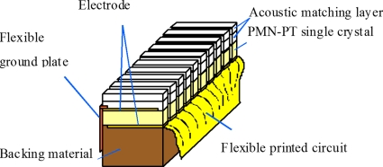
After characterizing the piezoelectric properties of the PMN-PT single crystal, the crystal was used for subsequent phased-array transducer fabrication. Before fabrication, the KLM equivalent circuit based software package PiezoCAD (Sonic Concepts, Woodinville, WA) was used for the evaluation of transducer design. Figure 1 shows the construction of the transducer. The designed frequency fd of the array was 3.2 MHz. An element center-to-center spacing, or pitch, of 0.28 mm was selected. To eliminate the back-wall reflections and to provide a short ring-down time, a highly attenuating backing with acoustic impedance matched to that of single crystal was used. In this work, two types of backing materials were considered: (1) mixture of 5 μm tungsten powder, microbubbles, and epoxy Epotek 301 with high acoustic impedance of ∼16 MRayls; (2) conductive epoxy E-solder 3022 (Von Roll Isola, New Haven, CT) with low acoustic impedance of ∼5.9 MRayls. To further enhance the transducer bandwidth and sensitivity, a double matching layer scheme was also employed. The ideal acoustic impedances of the first Zm1 and second Zm2 matching layers were calculated as follows:14
| (1) |
| (2) |
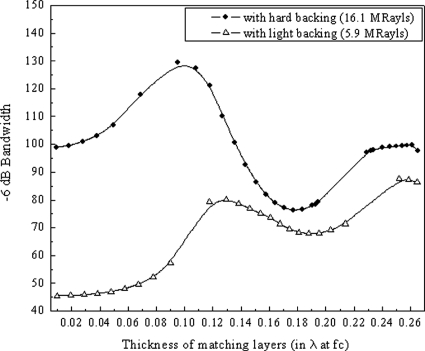
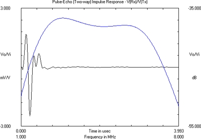
where Z1 is the impedance of the piezoelectric element and Z2 is the impedance of the load medium. For the PMN-28%PT, the acoustic impedance was ∼25.0 MRayls. The acoustic impedance of the load medium, typically tissue or water, is approximately 1.5 MRayls. The calculated values for Zm1 and Zm2 were 7.5 and 2.3 MRayls, respectively. In practice, a mixture of 2–5 μm alumina powder and Epotek 301 (with Zm1=6.5 MRayls), and Epotek 301 (with Zm2=3.1 MRayls) were prepared as the first and second front-face matching materials, respectively. The properties of materials used in the stimulation are listed in Table 2. The effect of the backing and the matching thicknesses on the transducer bandwidth was studied, and the modeled results are shown in Fig. 2. With light backing, a −6 dB transducer bandwidth of over 80% can be obtained when the thickness of the double matching layers is at ∼λ∕8 and λ∕4 of the transducer center frequency. By using hard backing, the bandwidth changes obviously with the matching thickness. For conventional double λ∕4 matching layers, the bandwidth is up to 100%. This result is much higher than the PZT transducer available in the market (∼70%). When the matching thickness is reduced to 0.1λ (around λ∕8), the bandwidth can reach as high as 130%, which is nearly double to that obtained with the PZT transducer. The design of the two λ∕8 matching layers can be considered as a single quarter matching layer that works as a simplified graded matching. From the results of the simulation with PiezoCAD, this kind of simplified graded matching can improve the bandwidth significantly with proper selection of the backing material. The model predicts an array element with a center frequency of 4.2 MHz, which is slightly higher than the designed frequency (3.2 MHz). The modeled time domain and frequency domain response for this array element is shown in Fig. 3. Thus, a 16-element phased-array transducer (with double λ∕8 matching layers and hard backing) was fabricated following the stimulation results. The detailed description of the fabrication procedure for the transducer will be given in Sec. 4.
Figure 1.
Construction of a PMN-PT phased-array transducer.
Table 2.
Properties of PMN-PT and passive materials used in the transducer.
| Material | Use | ρ (kg∕m3) | c (m∕s) | Za (MRayls) | Loss at 3.2 MHz (dB∕mm) |
|---|---|---|---|---|---|
| PMN-PT | Active element | 8100 | 3950 | 32.0 | N∕A |
| 2–5 μm Al2O3∕Epotek 301 | Matching layer 1 | 2300 | 2800 | 6.4 | 1.68 |
| Epotek 301 | Matching layer 2 | 1150 | 2650 | 3.1 | 1.04 |
| Esolder 3022 | Light backing | 3200 | 1850 | 5.9 | 11.8 |
| 5 μm tungsten particles∕microbubbles∕Epotek 301 | heavy backing | 8925 | 1800 | 16.0 | 16.0 |
Figure 2.
Stimulation of −6 dB transducer bandwidth with different matching thicknesses (in λ at fc of the array element) on light and hard backings.
Figure 3.
Modeled time and frequency domain pulse∕echo response for a single array element with the center frequency of 4.2 MHz.
TRANSDUCER FABRICATION AND CHARACTERIZATION
Mixture of alumina powder and Epotek 301 was lapped down and polished to the designed thickness of 75 μm as the first matching layer. The second matching layer, Epotek 301, was casted on the first matching layer and then cured at 50 °C overnight. The second matching layer was lapped down and polished to the thickness of 70 μm. The thicknesses of the two matching layers are the optimized results from the PiezoCAD stimulation. For the backing layer, a mixture of tungsten power∕microbubbles∕Epotek 301 with thickness of 3.5 mm was used. Both surfaces of the backing were polished before subsequent transducer fabrication.
A flexible circuit with 150 μm gold wire arranged with a constant pitch of 0.26 mm was connected to one edge of the PMN-PT single crystal (coated with Cr∕Au electrodes on both surfaces) with conductive epoxy Epotek EE129-4 and then cured at 50 °C overnight. The double matching layers, PMN-PT single crystal, and the backing layer were bonded together with a solvent-thinned epoxy-phenoic adhesive (M-bond 610) under external pressure to provide a thin bonding line. The multilayer stack was cured at 50 °C overnight. A dicing saw (model DAD 321, DISCO, Japan) was used to dice apart individual array elements and electrodes. Dicing speed was set at 0.5 mm∕s and dicing depth was 1.05 mm (0.3 mm into the backing layer) to eliminate the cross-talk between neighbor elements. The element pitch is 0.20 mm, and the kerf width is 0.08 mm. The subsequent array kerfs were filled with epoxy (Ciba-Geigy, 5 min Aralidite). After connecting the top electrode of every element with conductive epoxy (served as a grounding), the array was housed in an external cylindrical plastic housing.
To evaluate the transducer’s performance, a set of measurements was performed. The electric impedance of the transducer was measured using an HP 4192 impedance analyzer. The center frequency, bandwidth, and insertion loss (IL) of the array element were tested using a pulse-echo response arrangement. The transducer, mounted on a water tank in front of a thick stainless steel target, was connected to a Panametrics 5900PR pulser∕receiver. The distance between the transducer and the target was 20 mm. The array elements were excited individually by 1 μJ electrical impulse with 200 Hz repetition and 50 Ω damping. The echo response was captured by the receive circuit of the 5900PR. A gain of 26 dB was used to amplify the signal to a satisfactory amplitude, so that it could be displayed on an oscilloscope (HP Infinium). The Fast Fourier Transform (FFT) math feature on the oscilloscope was used to display the frequency domain pulse∕echo response. To determine the characteristics of the array element, the following parameters were calculated from the measured frequency spectrum.15
-
(a)
Lower and upper −6dB frequencies (fl and fu): the frequencies at which the magnitude of the amplitude in the spectrum is 50% (−6 dB) of the maximum,
-
(b)Center frequency:
(3) -
(c)−6 dB bandwidth:
(4)
The two-way IL, or the relative pulse-echo sensitivity, is the ratio of the output power Po of the transducer to the input power Pi delivered to the transducer from the driving source. By assuming that the input load resistance Ri and output load resistance Ro is equal, the IL can be simplified to the following form:
| (5) |
where Vo and Vi are the amplitude of the echo and the input driving voltage, respectively.
To measure the IL, an HP8116A function generator with 50 Ω output impedance was used to generate a tone burst of a 15-cycle sine wave with an amplitude Vi at center frequency of the transducer, as measured by the oscilloscope (HP Infinium) with 50 Ω coupling. By connecting the transducer to the function generator, the voltage amplitude Vo of received echo was measured using the oscilloscope with 1 MΩ coupling.
TRANSDUCER PERFORMANCE
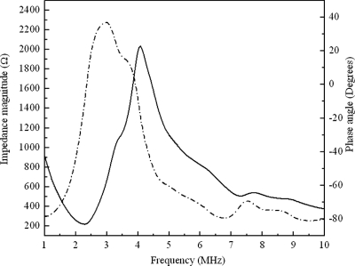
The impedance and phase spectrum of the PMN-PT phased-array transducer were measured in air using an impedance analyzer, and the results are shown in Fig. 4. The resonance frequencies fr and fa attributed from the thickness mode vibration are found at 2.28 and 4.08 MHz, respectively. The relative electromechanical coupling factor is 0.80.
Figure 4.
Measured electrical impedance magnitude and phase angle for the array element. The solid and dotted lines represent the impedance and phase, respectively.
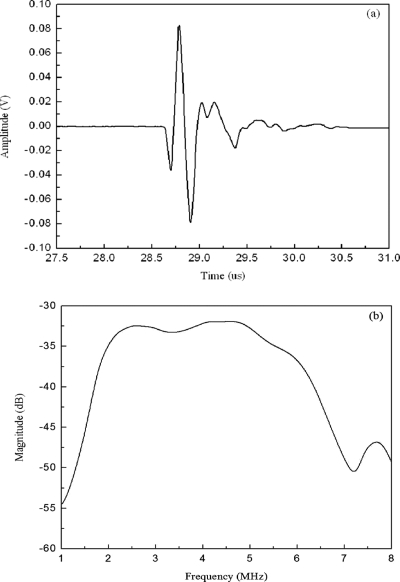
The pulse-echo response of the transducer was characterized in a water tank at room temperature. Figure 5 shows the pulse-echo response and frequency spectrum of the array element. From Eqs. 3, 4, the center frequency of the array element is found to be 4.0 MHz and the −6 dB bandwidth is 110 %. The two-way IL calculated by Eq. 5 is about −46.5 dB at fc after compensation for attenuation caused by the water (2×10⁻⁴f2 dB∕mm, f in MHz) and reflection from the stainless steel target (0.87). As shown in Fig. 5a, a ring down is observed indicating that the vibration is not perfectly damped and this can reduce the transducer bandwidth. Thus, the measured bandwidth is slightly lower than the modeled result. However, by using double λ∕8-matching layers and hard backing, the transducer with bandwidth over 100% is achieved.
Figure 5.
(a) Pulse-echo impulse response and (b) frequency spectrum of the array element.
CONCLUSIONS
A 4.0 MHz phased-array ultrasound transducer (with 16 elements) using PMN-PT single crystal has been fabricated and characterized. In order to design a high performance transducer, a commercial PiezoCAD simulation was used to study the effect of the matching layers and backing on the performance of the transducer. Optimization of the acoustic scheme for the transducer was done based on the modeled results. The transducer with double λ∕8-matching layers and hard backing give a bandwidth of 110%, which is much higher than the commercial PZT transducer (∼70%). The results suggest the potential substitution of the PMN-PT single crystal as active materials for next generation high performance phased array transducer.
ACKNOWLEDGMENTS
This work was supported by the Hong Kong Innovative Technology Council (Project No. K-ZP-21) and the Centre for Smart Materials of the Hong Kong Polytechnic University. The authors would like to thank Mr. Jay Williams for his help and the support from NIH Grant No. P41-EB2182.
References
- Gururaja T. R., W. A.Schulze, Jr., Cross L. E., Newnham R. E., Bertram A. A., and Wang Y., IEEE Trans. Sonics Ultrason. SU-32, 481 (1985). [Google Scholar]
- Lockwood G. R., Turnbull E. H., and Foster F. S., IEEE Trans. Ultrason. Ferroelectr. Freq. Control 41, 231 (1994). 10.1109/58.279136 [DOI] [Google Scholar]
- Goldberg R. L. and Smith S. W., IEEE Trans. Ultrason. Ferroelectr. Freq. Control 10.1109/58.308512 41, 761 (1994). [DOI] [PubMed] [Google Scholar]
- Kuwata J., Uchino K., and Nomura S., Jpn. J. Appl. Phys., Part 1 10.1143/JJAP.21.1298 21, 1298 (1982). [DOI] [Google Scholar]
- Park S. E. and Shrout T. R., IEEE Trans. Ultrason. Ferroelectr. Freq. Control 10.1109/58.655639 44, 1140 (1997). [DOI] [PubMed] [Google Scholar]
- Saitoh S., Takeuchi T., Kobayashi T., Harada K., Shimanuki S., and Yamashita Y., IEEE Trans. Ultrason. Ferroelectr. Freq. Control 10.1109/58.753031 46, 414 (1999). [DOI] [PubMed] [Google Scholar]
- Oakley C. G. and Zipparo M. J., Proc.-IEEE Ultrason. Symp. 2, 1157 (2000). [Google Scholar]
- Lu X. M. and Proulx T. L., Proc.-IEEE Ultrason. Symp. 1, 227 (2005). [Google Scholar]
- Chen J. and Panda R., Proc.-IEEE Ultrason. Symp. 1, 235 (2005). [Google Scholar]
- Edmiston Rick, “Triple Quarter-Wave Transducer Designs,” www.STI-Ultrasound.com (2005).
- Sato S., Katsura H., and Kobayashi K., Proc.-IEEE Ultrason. Symp. 2, 1235 (2002). [Google Scholar]
- Felix N., Ratsimandresy L., and Dufait R., Proc.-IEEE Ultrason. Symp. 2, 1123 (2001). [Google Scholar]
- Yin Z. W., Luo H. S., Wang P. C., and Xu G. S., Ferroelectrics 10.1080/00150199908224341 231, 207 (1999). [DOI] [Google Scholar]
- Cannata J. M., “High frequency (>20 MHz) ultrasonic arrays for medical imaging applications,” Ph.D. thesis, The Pennsylvania State University, 2004. [Google Scholar]
- American Institute of Ultrasound in Medicine, (AIUM), ‘‘Standard methods for testing single-element pulse-echo ultrasonic transducers,” J. Ultrasound Med. 1, Sep. 1982.


