Abstract
We have developed a compact, computer-piloted, high sensitivity broadband imaging system for laboratory research that is compatible with various detectors. Mirror optics allow application from the visible to the far infrared spectral range. A prototype tested in conjunction with a mercury cadmium telluride detector exhibits a peak detectivity of 6.7×1010 cm Hz1∕2∕W at a wavelength of 11.8 μm. Temperature and spatial resolutions of 0.06 K and 1.6 mrad, respectively, were demonstrated.
Measurement of the intensity of emitted or transmitted infrared (IR) radiation, as well as its spatial and spectral distribution,1 is a key task which enables many medical-biological, physical, and chemical experiments.2, 3, 4 As a rule, commercial infrared measurement systems operate only in the spectral ranges of 3–5 or 8–14 μm.5 However, very high and very low temperature processes, as well as phenomena that accompany nonthermal radiation emission, require broader sensitivity. The problem can be addressed using a system compatible with multiple detectors. Therefore, we have designed and prototyped a computer-piloted, compact, broadband, high sensitivity imaging system for laboratory research (ISLR). Due to its open architecture and modular design, the system possesses a number of advantages. The ISLR is compatible with a range of different detectors (including LHe-cooled detectors). Calibrated radiation sources may be introduced into the measurement channel, and different scanning formats may be flexibly implemented. These special features provide improved (i) spectral range, (ii) accuracy, and (iii) flexibility. We report on thermal imaging system performance using a single pixel HgCdTe detector cooled by liquid nitrogen.
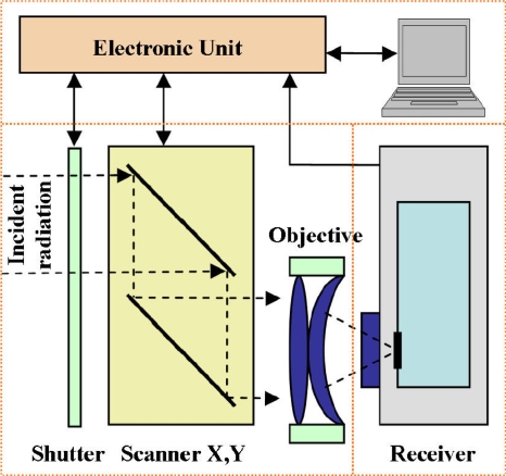
As shown in Fig. 1, the ISLR consists of the three following principal modules: (i) an optomechanical module, including the shutter, two-dimensional mirror scanner and objective, (ii) the receiver, including the detector and its cooling system, and (iii) an electronics unit, including a scanner controller and data processing equipment. Incident radiation travels from a given point on the surveyed object, through the focusing lens to the detector, generating an electrical signal. In this way, the spatial distribution of the thermal field intensity is transformed into an electrical signal. The spectral range of the ISLR is determined by the choice of detector and optical system, which may be changed without difficulty to suit a given application. Thermograms may be stored and displayed graphically via digital image processing performed on a personal computer (PC) or personal digital assistant (PDA). Custom software enables digital processing of the video signal. The scanner and electronics module comprise a single unit which may be integrated with the detector and focusing optics.
Figure 1.
Block diagram of the ISLR.
The full rectangular image is formed from the combination of line (horizontal) and frame (vertical) sweeps. Horizontal scanning is accomplished by oscillation of a suspended 36×50 mm2 mirror connected to a steel spring. Oscillations are sustained by a sequence of rectangular current pulses driving two electromagnets located underneath the mirror. The scanner controller adjusts the pulse power applied to the deflection electromagnet through the pulse duration. The resonant frequency in this configuration is governed by the mirror mass and the spring geometry, and is typically of order ∼100 Hz. To avoid distortions in the thermal image, only spring displacements in the quasilinear regime are employed. This limits the useful angle of mirror deflection to 23°, although the full mechanical deflection is twice that. The instantaneous position of the mirror is monitored by an light-emitting diode∕photodiode optocouple sensor which outputs an electrical signal proportional to the mirror deflection angle. The deflection amplitude is set by the gain of the position sensor amplifier and is closely controlled utilizing the position signal and a proportional-integral feedback algorithm. This scheme maintains a stable deflection angle despite changes in the resonant frequency due to environmental temperature variations (about 5 Hz variation between 0 and 40 °C).
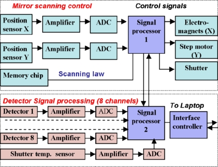
Another mirror, 60×60 mm2 in size, provides scanning in the vertical plane. The mirror is driven by a unipolar four-phase stepper motor with an angular resolution of 1.8°. A mechanical reduction with a stepdown factor of 30 is also employed. The electronic motor control pulse sequence is generated by signal processor 1 (refer to Fig. 2) within the electronics unit. Rotation is bidirectional, and the scanning law is programmable. Therefore, complex scanning functions may be flexibly implemented. An optical sensor indicates the extreme position of the vertical scanning mirror. Both vertical and horizontal scanning mirrors are coated with aluminum to provide good reflectivity across a broad spectral range.
Figure 2.
Schematic of the electronics unit.
The ISLR can remotely measure the emissivity and absolute temperature of objects in its field of view using chopping of the input optical signal. Shuttering the system field of view at the end of each frame (that is, during the backward rotation of the frame-sweep mirror) achieves this purpose. The detector is exposed only to thermal radiation from the shutter surface, which is a calibrated source of known emissivity, during the half-cycle when the shutter is closed. Because the shutter temperature is controlled by the signal processor, a map of the radiation intensity in the field of view may be generated with reference to a calibrated thermal source. Placement of the shutter at the entrance of the optical system eliminates errors caused by thermal non-equilibrium between the components in the optical path. The closed position of the shutter is indicated by an optoelectronic sensor.
Due to the location of the detector on the system optical axis, the requirements regarding lens quality are not strenuous. Two interchangeable objectives were designed and implemented. The first of these consists of two lenses, made from germanium, and utilizes antireflection coatings to obtain a flat transmission characteristic (∼0.9) in the spectral range from 2 to 18 μm. This objective possesses an aperture D=32 mm and focal ratio f∕1. The second objective covers the short- and long-wave portions of the IR spectrum using a Cassegrain mirror system with the same aperture and a focal ratio f∕1.5. A reduction gear was employed to adjust the image focus by moving the objective along the optical axis.
The compatibility of the ISLR with various detectors, including cryogenic detectors, is its most attractive feature. In addition to commercially available cryogenic systems suitable for liquid nitrogen6 and liquid helium7 cooling, we have developed a compact, dismountable, 77 K optical cryostat. This cryostat requires 150 ml of LN2 per charge, is 50 mm in diameter and 150 mm tall, and maintains the detector at operating temperature for more than 8 h. The cryostat vacuum joints and entrance window (25 mm diameter) utilize bolts, so that it is possible to change both the detector and the entrance window, as necessary for a given application.
Inside the cryostat, the detectors are placed on a temperature-controlled platform in vacuum. Up to 8 single pixel detectors (or a single 1×8 array) can be accommodated. Cold diaphragms are installed to match the chosen detector and the optical system. The photoinduced signal is amplified with low noise preamplifiers providing a gain of ∼200 with an electrical noise level below 2 nV∕Hz1∕2 in the frequency band from 0 to 100 kHz.
The electronics module (shown in Fig. 2) is based on an ADSP-2188 signal processor. This is a high-speed 16 bit microcomputer with a well-developed interface for peripheral devices analog-to-digital converter (ADC), digital-to-analog converter, etc. The module is designed as a single board, and can be conventionally divided into the following functional units: the scanner-control unit, the video signal processing unit, and the interface controller for data communication with a PC via universal serial bus (USB).
The line sweep timing signals generated by the microprocessor correspond to the initial and final angular positions of the horizontal (line) mirror. Line generation occurs in both the forward and backward raster directions, with the line counter incrementing by 1 at the end of each line. The maximum number of lines is user-definable, up to 256. When the line counter overflows, the microprocessor returns the vertical (frame) mirror to its extreme position (overscan backward run), as indicated by the optical sensor at that location. The shutter is closed during the backward run, and the line sweep timing signals are ignored during this time. The backward movement of the frame sweep mirror is quick (≈500 ms), after which the line counter is nullified, the frame sweep timing signal is generated and the scanner starts over, forming the new raster. Shutter commands and timing signals for line and frame sweeps are passed between signal processors 1 and 2.
The video signal is digitally processed, starting with conversion to a 12 bit digital data stream at a sampling rate of 100 kHz. A scaling amplifier matches the dynamic range of the photoreceptor detector to the ADC. The signal processor next digitally filters the video signal in real time, subtracts the background signal, and outputs to a PC a two-dimensional array of numeric data regarding the intensity of the thermal field. The IR image is graphically displayed in a pixel map. The image format is defined not only by the number of lines in a raster (up to 256) and the video signal sampling rate, but also by the mechanics of the line sweep mirror. No data is taken at points outside of the quasilinear spring displacement limit, at a deflection angle of 23°. Because two overlapping image lines are formed during one cycle of the line mirror, which lasts 10 ms, the 100 kHz sampling rate can provide 256 elements in each image line.
Two 256×2 byte random access memory buffers in signal processor 2 temporarily store line sweep data. Buffer filling is synchronized to the line sweep timing signals generated by the scanner-control unit. Once a line scan is complete and the buffer is full, a signal to the interface controller initiates data exchange with the PC and transmits the current image line. The line number is also transmitted, which allows IR image formation in real time. Separate buffers are employed for even and odd numbered lines, which eases requirements on the data transmission rate to the PC.
The emitter junction of a chip transistor mounted on the thermal flux shutter serves as a microthermometer. This device is biased using a thermostabilized dc source. When the shutter is closed during the backward run of the frame sweep mirror, the multiplexer switches the ADC to the output of an amplifier connected to the thermometer. Therefore, the final line of each frame records the shutter temperature. In addition to recording the shutter temperature during this interval, the signal processor is programmed to average and record the detector photoresponse to the thermal radiation from the closed shutter. This average value is subtracted from the total video signal during the next frame, which allows absolute temperature values to be determined.
The portion of the electronics unit which processes the detector signal consists of eight parallel input channels, each comprised of an amplifier and a 12 bit ADC. Its capabilities include channel equalization, digital processing and signal filtering, recovery of the dc base band signal level, and data storage in an internal video buffer. A video signal processing module is also contained within the electronics unit. This module generates the end-of-frame signal, which transmits it to an interface controller, synchronizing data exchange. The interface controller connects to the signal processor through the internal direct memory access port on that device, enabling digital data transmission to a PC or PDA. An FT245R chip serves as the basis for the interface controller, which includes a parallel interface with a first-in, first-out (FIFO) buffer and a USB transceiver for high transmission speed. The interface controller operates in compliance with USB 2.0 (high speed) or USB 1.0 standard specifications. Data transmission is realized line by line synchronized to the control pulse from the video signal processing unit. One 256×2 byte buffer is transmitted at a time.
Two original software packages were developed for this instrument, one in the DELPHI programming language under the Windows operating system for use on a laptop computer, and the second in Pocket Programming Language under the Windows Mobile operating system for use with a PDA. Both allow real time visualization of thermal fields, as well as postacquisition image analysis. The interfaces support standard manipulation of recorded data files, provide measurement of the absolute temperature at each image point, and allow modification of colors and palettes.
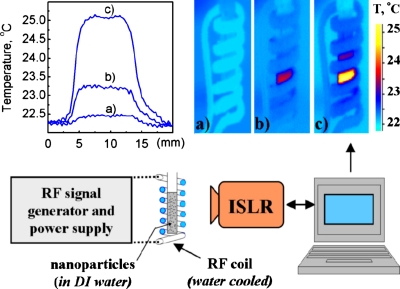
The ISLR instrument was tested utilizing a 50×50 μm2 mercury cadmium telluride photoresistor sensor cooled with liquid nitrogen.6 The average detectivity of this device is D*≈3×1010 cm Hz1∕2∕W in the 8–14 μm spectral range. The properties of the ISLR in this configuration are summarized in Table 1. The ISLR system has been successfully applied to a variety of research problems, including measurement of the absolute temperature of magnetic nanoparticles suspended in liquid and subjected to high-frequency electromagnetic heating8 (Fig. 3), medical research involving precise measurements of the skin temperature fields of chemoradiotherapy patients,9 etc.
Table 1.
Measured performance of the ISLR equipped with mercury CdMgTl detector.6
| Spectral range (μm) | 8–14 |
| Field of view (deg) | 24 H×24 V |
| Spatial resolution (mrad) | 1.6 |
| Image resolution | 256×256 |
| Frame scanning time (s) | 1.5 |
| Temperature resolution (deg) | 0.06 at 30 °С |
| Measurement accuracy (%) | ±2 |
Figure 3.
IR images of the nanoparticles inductive heating process (Ref. 8) (images were taken in the 8–14 μm spectral range). The inset shows the temperature distribution across the sample.
Acknowledgments
The work at Argonne National Laboratory was supported by Office of Science and Office of Basic Energy Sciences of the U.S. Department of Energy, under Contract No. DE-AC02-06CH11357. Partial funding was provided by NIH “Functional Infrared Imaging Predicts Radiation Mucositis,” Grant No. 1R21CA125000-01A1.
References
- Maldague X. P., Theory and Practice of Infrared Technology for Nondestructive Testing (Wiley, New York, 2001). [Google Scholar]
- Diakides N. A. and Bronzino J. D., Medical Infrared Imaging (CRC, Boca Raton, FL, 2007). [Google Scholar]
- Cernuschi F., Russo A., Lorenzoni L., and Figari A., Rev. Sci. Instrum. 72, 3988 (2001). 10.1063/1.1400151 [DOI] [Google Scholar]
- Vainer B. G., J. Phys. D: Appl. Phys. 41, 065102 (2008). 10.1088/0022-3727/41/6/065102 [DOI] [Google Scholar]
- FLIR Systems Inc (www.flir.com/US/).
- Judson Technologies, #J15D12 (http://judsontechnlogis.com).
- Oxford Instrument, OptistatCV-V (http://.oxford-instruments.com).
- Liu X., Novosad V., Rozhkova E., Chen H., Yefremenko V., Pearson J., Torno M., Bader S., and Rosengart A., IEEE Trans. Magn. 43, 2462 (2007). 10.1109/TMAG.2007.894004 [DOI] [Google Scholar]
- Sagoff J., “New thermal-imaging technique may help victims of head and neck cancers,” Argonne News. 60, No. 23, 1 (2007), www.anl.gov/Media_Center/News/2007/MSD071226.html.


