Abstract
The SlipChip is a microfluidic device designed to perform multiplexed microfluidic reactions without pumps or valves. The device has two plates in close contact. The bottom plate contains wells preloaded with many reagents; in this paper plates with 48 reagents were used. These wells are covered by the top plate that acts as a lid for the wells with reagents. The device also has a fluidic path, composed of ducts in the bottom plate and wells in the top plate, which is connected only when the top and bottom plate are aligned in a specific configuration. Sample can be added into the fluidic path, filling both wells and ducts. Then, the top plate is “slipped”, or moved, relative to the bottom plate so the complementary patterns of wells in both plates overlap, exposing the sample-containing wells of the top plate to the reagent-containing wells of the bottom plate, and enabling diffusion and reactions. Between the two plates, a lubricating layer of fluorocarbon was used to facilitate relative motion of the plates. This paper implements this approach on a nanoliter scale using devices fabricated in glass. Stability of preloaded solutions, control of loading, and lack of cross-contamination were tested using fluorescent dyes. Functionality of the device was illustrated via crystallization of a model membrane protein. Fabrication of this device is simple and does not require a bonding step. This device requires no pumps or valves and is applicable to resource-poor settings. Overall, this device should be valuable for multiplexed applications that require exposing one sample to many reagents in small volumes. One may think of the SlipChip as an easy-to-use analogue of a preloaded multi-well plate, or a preloaded liquid-phase microarray.
Introduction
This paper describes the SlipChip, a microfluidic device for carrying out multiplexed solution-phase experiments in a simple format. Multiplexed experiments are common, especially in applications that require screening. Miniaturization and simplification of these experiments are attractive to minimize both sample volume and labor costs and to improve efficiency. Various microfluidic systems have been developed to perform multiplexed experiments on the nanoliter scale.1–18 Sophisticated approaches have used valve-based systems4 to route the sample to many reaction chambers that can in turn be loaded with many different reagents. These systems required external equipment for hydraulic control and used gas-permeable materials for dead-end filling, which made storing reagents on-board difficult.19,20 Compact-disc (CD)-based microfluidic devices based on fluidic control with electroosmotic flow,21 pneumatic valves11 or centrifugal force combined with capillary burst valves1,14 have been developed, which have performed several hundreds of parallel assays on one CD. However, the fabrication of CD-based-systems is complex, and high-precision mechanics is required for control of flow and for detection. Microplate-based-systems22 are very attractive due to their easy fabrication and high throughput, but these systems face a number of technical hurdles, such as storing nanoliter solutions in microwells, controlling humidity, and limitations of parallel low volume liquid-dispensing technologies.12,17 Plug-based systems,23–25 in which the sample volumes are surrounded by an immiscible carrier fluid, can also be used to perform multiplexed experiments. They are especially attractive because they simplify control of surface chemistry, which is important for experiments on the microscale. They replace the need to control the surface chemistry of the device–sample interface with a simpler task: controlling the carrier fluid–sample interface. When fluorinated carrier fluids are used, the fluorous–aqueous interface can be controlled by using fluorinated amphiphiles;26 this approach has been recently further optimized.27 The control of surface chemistry allows reducing non-specific adsorption.26,28,29 Plug-based hybrid approaches also screen both reagents and their concentrations30 and require external pumping control. Pre-formed cartridges of plugs simplify the experiment for the user by requiring only a single source of pressure to combine the sample with the pre-made cartridge.31–33 Coalescence of the sample stream with the plugs is well understood and can be controlled,34,35 but such devices have not yet been mass-produced.
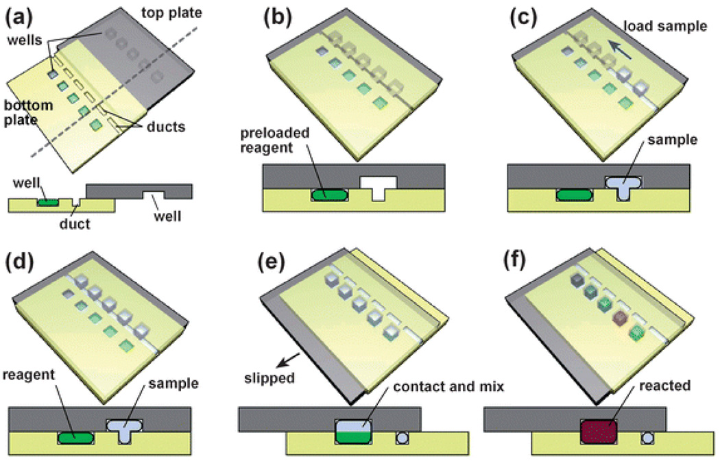
Here we describe the SlipChip, a device and method for performing multiplexed experiments that preserves the control of surface chemistry provided by plug-based systems, while simplifying fabrication and operation. The SlipChip is similar to the preloaded plate-based method previously described.7,12 In one such system,12 operated by the PDMS microchannel degassing method, different reagents were loaded into the wells in one microwell plate, the sample was loaded into wells in another microwell plate, and the two preloaded plates were brought together so that the wells in the top and bottom plates could contact each other, inducing mixing of reagents and the sample. The SlipChip also consists of two plates, but in contrast to the previous methods, the two plates are designed to be in contact and are not separated during use (Fig. 1, see also ESI movie S1†). The bottom plate contains an array of wells. In the device described in this paper, these wells were preloaded with reagents (Fig. 1a). In addition, the bottom plate contains an array of disconnected ducts that are involved in loading (Fig. 1a). The top plate serves as a lid for the wells of the bottom plate (Fig. 1b) and also contains an array of wells that 1) are complementary in pattern to the array of wells in the bottom plate and 2) connect the ducts of the bottom plate into a continuous fluidic path. The user receives the chip in the assembled form (Fig. 1b). The sample is added through the fluidic path provided by the ducts and wells (Fig. 1 c,d). To expose the sample wells to all of the corresponding reagent wells simultaneously, the top plate is slipped relative to the bottom plate (Fig. 1e). Mixing takes place, and the results of the experiments are read out (Fig. 1f). Sliding two pieces of a device is common in devices that regulate fluid flow, from a standard HPLC valve to more sophisticated microfluidic devices.36–38 In addition, sliding has been used to induce reactions5 and to induce shear flow in shear-driven chromatography.39,40 The SlipChip builds on these advances, and the advances in plug-based microfluidics, to provide a platform that delivers controlled volumes of samples to many reaction wells in a simple and functional format.
Fig. 1.
Step-by-step 3D schematic drawings with cross-sectional views that describe the operation of the SlipChip. (a) Off-set view that shows the preloaded wells of the bottom plate, the ducts of the bottom plate, and the wells of the top plate. (b) View of the device available to the user, in which the top and bottom plates are aligned. (c) and (d) Loading of a single sample through the overlapping ducts of the bottom plate and wells of the top plate. (e) Slipping of the top plate relative to the bottom plate disconnects the sample wells of the top plate from the ducts of the bottom plate, and then exposes the sample wells to the wells of the bottom plate containing reagents. (f) The red well schematically shows a reaction taking place after mixing and incubation (see also movie S1†).
Experimental
Fabricating the SlipChip
Soda-lime glass plates with chromium and photoresist coating were used for fabricating devices. Microchannels and wells on the glass plates were made by using standard photolithographic and wet chemical etching techniques.41 The dimensions of the wells were 320 µm × 320 µm laterally and 60 µm in depth. The surfaces of the etched glass plates were cleaned and subjected to an oxygen plasma treatment, and then the surfaces were rendered hydrophobic by silanization in a vacuum desiccator as described.42 Access holes were drilled with a diamond drill bit 0.030 inches in diameter. The plates were rinsed clean with ethanol, blown dry with nitrogen gas, and kept in clean Petri dishes.
Preloading the SlipChip with reagents
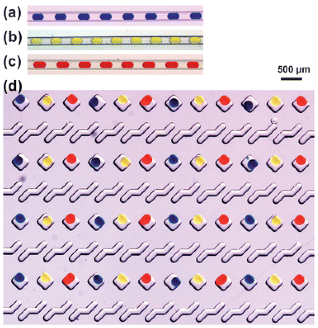
A piece of Teflon tubing containing the plugs (Fig. 2 a–c, see ESI methods for procedure†) of solutions of reagents was connected to a 5 cm-long piece of Teflon tubing (I.D. 370 µm), which was connected to a 10 µL syringe. Using a micro-manipulator to drive the syringe, the reagent plugs were deposited into the designated wells on the bottom plate of the Slip Chip, each plug into one well. The deposition was performed under FC-40 to prevent evaporation. First the bottom plate (500 µm thick), with the wells and ducts facing up, was placed in a 3.5-inch Petri dish containing 2–3 mm deep FC-40. To facilitate the loading process, the open end of the Teflon tubing was aimed at the well of deposition from an angle 45 degrees, with one side of the tube pushing against the bottom of the well. One plug was then pushed out using the micro-manipulator. We found the droplet did not float up easily even though the density of the solution in the droplet (~1 × 10³ kg m−3) was smaller than FC-40 (1.9 × 10³ kg m−3). Presumably, the aqueous solution was pinned to the surface of the well. However, if the open end of the tubing was lifted during loading, the droplet would float. Once the droplets were deposited, they did not float. 48 wells were loaded with three different dyes in a repetitive pattern of blue-yellow-red (Fig. 2d). The whole preloading process took less than 10 minutes. After preloading, each well contained ~5 nL of blue, yellow or red dye solution.
Fig. 2.
(a), (b) and (c) Microphotographs of plugs with uniform volumes of food dye solutions stored in Teflon tubing. The plugs were formed in a flow focusing device in three separate experiments. (d) Microphotograph of the wells in the bottom plate of a SlipChip. The wells were loaded with plugs of the solutions of food dye in a repeating pattern.
Assembling the SlipChip
Under FC-40, the top plate was placed onto the bottom plate, which contained preloaded reagent solutions (see above). The ducts in the bottom plate were overlapped with the empty wells in the top plate, forming a continuous fluidic path for loading of the sample (Fig. 3b,c). The two halves of the device were secured by using two small binder clips. Since the surfaces of both plates were hydrophobic and fluorophilic, we expected a thin layer of FC-40 to be trapped between both plates, filling any small defects. In addition, FC-40 has a boiling point of 158–173 °C and a low vapor pressure of 398 Pa, so evaporation was not an issue, especially when the device was stored under FC-70.
Fig. 3.
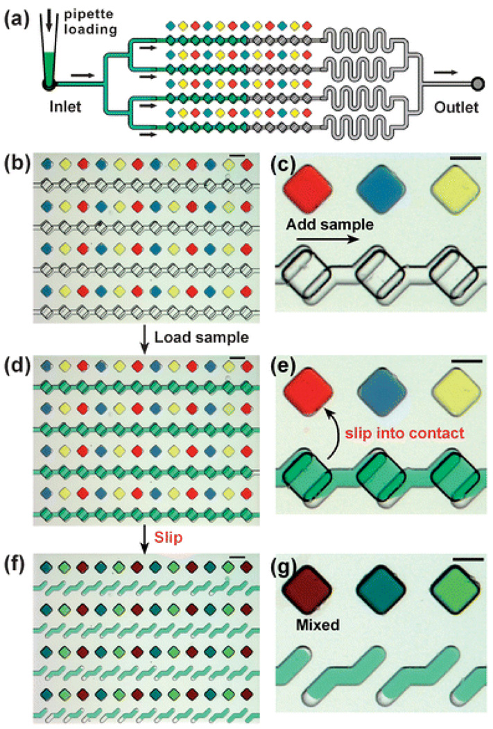
Operation of the SlipChip illustrated experimentally with food dyes. (a) A top-down schematic drawing of pipetting sample into the SlipChip used in the experiments. (b) A top-down microphotograph of a glass SlipChip with 48 reagent wells preloaded with red, blue, and yellow solutions of food dyes. (c) A zoomed-in microphotograph of the device shown in (b). (d) A top-down microphotograph of the SlipChip shown in (b) after the ducts and wells were filled. Filling was done by pipetting 0.5 µL of a solution of green food dye into the inlet. (e) A zoomed-in microphotograph of device shown in (d). (f) A top-down microphotograph of the SlipChip shown in (d) after the top plate was slipped to expose the sample wells to the reagent wells. Ducts filled with the solution of green food dye are visible. (g) A zoomed-in microphotograph of the device shown in (f). Scale bars for (b), (d) and (f) are 500 µm and for (c), (e) and (g) are 250 µm.
Loading a sample into the SlipChip by pipetting
A 10 µL pipettor tip containing sample solution was inserted into the inlet of the fluidic path in the assembled SlipChip (Fig. 3a). The solution was dispensed into the ducts and sample wells by pushing the button of pipettor manually (Fig. 3d,e). If during storage any evaporation of FC-40 happened from the device, air bubbles would form in the fluidic path. In that case, ~10 µL of FC-40 could be pushed into the fluidic paths to purge the air bubbles. Evaporation and formation of air bubbles could be avoided by storing devices under FC-70.
Slipping to mix a sample with reagents
The top plate was then moved relative to the bottom plate again to align the sample-containing wells in the top plate with the dye-containing wells in the bottom plates. Since the wells from both plates shared the same pattern and shape, all the wells in the top plate fully overlapped those in the bottom plate. Once the SlipChip was aligned, the sample (green dye) and reagents (blue, yellow, and red dyes) in both plates mixed by diffusion (Fig. 3f,g).
Crystallization of reaction center on the SlipChip
The protein sample of photosynthetic reaction center (RC) from Blastochloris viridis consisted of 36 mg mL−1 RC in 0.07% (w/v) LDAO, 7% (w/v) 1,2,3-heptanetriol, 4.5% (w/v) triethylamine phosphate (TEAP), 17 mM Na2HPO4/NaH2PO4 pH 6.0.
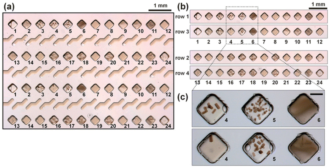
Arrays of plugs with 24 formulations (listed in Table S1†) were prepared. These plugs each constituted an individual crystallization trial. Next, the two top rows (rows 1 and 2) in the bottom plate of a SlipChip were loaded with these 24 arrays, one plug in each well. The two bottom rows (rows 3 and 4) were loaded with the plugs from the same arrays to create a replicate set of wells. The SlipChip was then assembled as described in the dye experiment. 1 µL of the RC sample was loaded into the SlipChip, followed by slipping to generate 48 crystallization trials. The trials were stored under FC-70 in the dark at room temperature (~23 °C). After two hours, crystals appeared. Microphotographs under dim light were taken of the fully assembled SlipChip and then of the wells in the SlipChip (Fig. 6a,c).
Fig. 6.
The crystallization conditions of the photosynthetic reaction center from Blastochloris viridis was screened against two sets of 24 precipitants in duplicate on the SlipChip. (a) A microphotograph of the SlipChip containing 48 crystallization trials after incubation for two hours. This image corresponds to the SlipChip after loading precipitants, adding solution of the protein, and slipping (as in Fig. 3f). Different precipitants are labeled as 1 through 24. Conditions 4 and 5 produced crystals in both sets of wells. (b) Side-by-side comparison of row 1 with row 3 and row 2 with row 4, illustrating reproducibility of the results between the duplicate sets of experiments. (c) Microphotographs of conditions 4, 5, and 6, which contained the same precipitant ((NH4)2SO4) with concentrations of 3.2 M, 3.6 M, and 4.0 M. As expected, a transition from a single crystal, to multiple crystals, to heavy precipitation was observed with the increase in precipitant concentration. The scale bar is 250 µm.
Results and discussion
We tested the idea of the SlipChip by fabricating one in glass with wells of ~6 nL volume (Fig. 2d) and silanizing it with tridecafluoro-1,1,2,2-tetrahydrooctyl-1-trichlorosilane to render the surface of the glass hydrophobic and fluorophilic. We loaded the bottom plate by first forming 5 nL plugs,23 using flow-focusing geometry in a PDMS device,43 of blue, yellow and red food dyes (Fig. 2 a–c), and then depositing these plugs into the wells of the bottom plate while the plate was submerged in the fluorocarbon lubricating fluid (Fig. 2d). Hundreds of plugs with precise volumes could be formed in a matter of a few minutes, sealed and stored for over a month.30 The droplets could float up in the denser fluorocarbon; if so, the filling would need to be done with the plate upside down. Whether the droplets remained in the wells was a function of both the shape of the wells and the details of the surface treatment. The ducts located on the bottom plate were not filled (Fig. 2d).
We assembled the device by adding the top plate and using a fluorinated fluid FC-40 as a lubricating layer between the two plates, using this fluid to fill all of the empty fluid elements (Fig. 3). We designed the channels to produce sufficient back pressure during filling to reduce the effects of capillary pressure.44 The ducts were empirically designed to improve filling. After the SlipChip was assembled (Fig. 3b,c), 0.5 µL of a solution of a green food dye was pipetted into the inlet to fill both the sample wells and the ducts (Fig. 3d,e). Slipping the top plate relative to the bottom plate disconnected the sample wells from the ducts, which became visible individually, and exposed the sample wells to the reagent wells (Fig. 3f,g). The slipping process took less than 10 s. No cross-contamination among wells during storage of the device or during slipping was observed due to the fluorocarbon fluid providing barriers among the wells, in a manner similar to the role of fluorocarbon carrier fluid preventing cross-contamination in preloaded cartridges of plugs.31–33
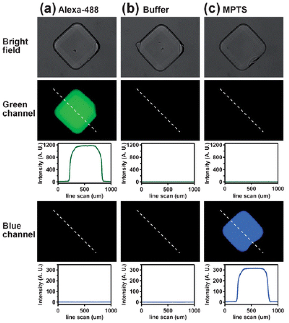
To evaluate cross-contamination among preloaded wells of the SlipChip with higher sensitivity, we loaded a green fluorescent dye (Alexa-488), buffer (10 mM Tris pH 7.8), and blue fluorescent dye (MPTS) into the wells in the same pattern as the food coloring in Fig. 3. To characterize possible cross-contamination, we measured the fluorescent intensity of solutions in the wells after 12 hours. We could not detect any cross-contamination: no blue dye was detected in the wells filled with the green dye (Fig. 4a), neither green nor blue dye could be detected in the wells filled with buffer (Fig. 4b), and no green dye was detected in the wells filled with the blue dye (Fig. 4c). Cross-contamination, if any, was less than 0.2% given the signal-to-noise ratio and the detection limit in this experiment. These solutions could be stored on the SlipChip for 772 hours (32 days) without significant changes in intensity. The coefficient of variation for intensity measured during storage was 4%, the overall change from the first time point to the final time point at 772 hours was less than 4% (see ESI methods and Fig. S1†).
Fig. 4.
No cross-contamination was detected in the preloaded SlipChip after 12 hours. Bright-field microphotograph (top), fluorescent microphotograph through the green channel (exciter: 480/40 nm; emitter: 527/30 nm) and corresponding intensity profile, and fluorescent microphotograph through the blue channel (exciter: 360/40 nm; emitter: 470/40 nm) and corresponding intensity profile are shown for the wells filled with (a) Alexa-488 dye, (b) buffer (10 mM Tris pH 7.8), and (c) MPTS dye.
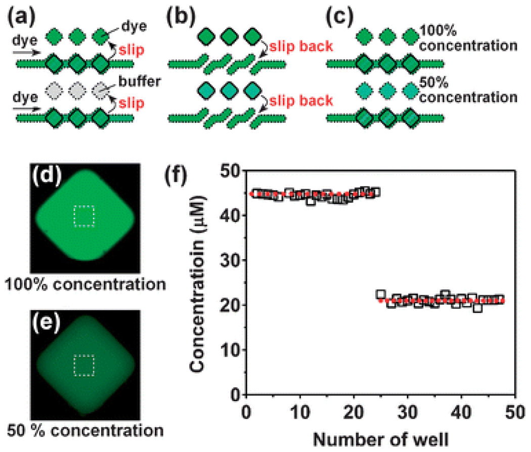
We evaluated the quality of filling of the wells in the SlipChip by doing a simple mixing experiment. We preloaded half of the wells with a 44.8 µM solution of a fluorescent dye Alexa-488 (wells 1–24), and the other half with the buffer (wells 25–48). We then filled the ducts and the sample wells with the same solution of the dye (Fig. 5a). A slipping step exposed sample wells to the preloaded wells, allowing mixing in 1 : 1 ratio solutions of either dye with dye, or dye with buffer (Fig. 5b). After incubation the top plate was slipped back to its original position, leaving behind the mixed solutions in the reagent wells of the bottom plate (Fig. 5c). We measured concentration of the dye in these wells using fluorescence microcopy after appropriate calibration experiments. Wells 1–24 served as the positive control and the concentration of the dye was 44.7 µM with a coefficient of variation of 3.9% (n = 23). In the remaining wells (25–48) the concentration of the dye was of 21.0 µM with the CV = 3.2% (n = 22), confirming that on the SlipChip both filling and mixing of solutions takes place with good accuracy and precision. For sufficiently thin wells brought into contact, mixing by diffusion can be made rapid even for large biomolecules. For thicker wells that may be required for some applications, especially those that rely on absorption measurements for detection, mixing may need to be accelerated. Slipping of two wells together in the SlipChip generates shear, and provides an attractive opportunity to design devices where shear can induce mixing by chaotic advection.45,46 In addition, convection and mixing is likely to be induced when slipping combines two liquids with contrasting densities, or contrasting surface tensions that induce Marangoni convection.
Fig. 5.
Filling and mixing of reagents on the SlipChip was consistent. (a) A schematic drawing of the SlipChip in which the reagent wells were preloaded with buffer and a fluorescent solution, with the same fluorescent solution added into the ducts and sample wells. (b) A schematic drawing of the same device after the slip. (c) A schematic drawing of the device after the top plate was slipped back to separate the sample from the well. (d) Fluorescent microphotograph of a well of 100% Alexa-488. (e) Fluorescent microphotograph of a well of 50% Alexa-488. (f) Concentration of the dye in wells 1–24 had a coefficient of variation of 3.9% (n = 23). Concentration of the dye in the remaining wells (25–48) had a coefficient of variation of 3.2% (n = 22), confirming accuracy and precision of both filling and mixing.
Finally, we tested the SlipChip by performing a simple crystallization experiment with a model membrane protein, the photosynthetic reaction center (RC) from Blastochloris viridis (Fig. 6). We loaded the SlipChip with two sets of 24 precipitants containing different concentrations of salts, polyethylene glycols, and buffers at different pH values (as in Fig. 3b). We then added 1 µL of the solution of the membrane protein to the sample wells via the ducts, as in Fig. 3d. Slipping exposed the solution of the membrane protein to the precipitants as in Fig. 3f. We picked this example for two reasons. First, we wished to test whether the SlipChip is capable of handling a diverse set of solutions, such as membrane proteins containing high (above CMC) concentrations of surface-active molecules. We found that both loading and slipping proceeded smoothly with these solutions, without any apparent adhering to surfaces of the device. Presumably the lubricating fluorocarbon layer helped isolate the solutions from the surfaces, analogous to the fluorocarbons isolating solutions of membrane proteins in plug-based microfluidic systems.30 Second, we wished to test the reproducibility of experiments on the SlipChip at least qualitatively. We found remarkably similar patterns of precipitation and crystallization for the two sets of precipitants (Fig. 6b). In both sets, crystals formed in the expected conditions containing (NH4)2SO4 in NaH2PO4/Na2HPO4 buffer, and we also observed the expected transition from single crystals, to multiple crystals, to precipitation as the concentration of the precipitant was increased from 3.2 M to 4.0 M (Fig. 6c).
Conclusion
The SlipChip described in this paper provides a method of introducing a solution into many wells preloaded with reagents (Fig. 1 and ESI Movie S1†). This approach preserves the control of surface chemistry provided by plugs26–29 and operates reliably at the nanoliter scale with a range of solutions, even with the diverse set used in protein crystallization. It is simple as it requires no external pumping or equipment for operation. Establishing compatibility with cell-phone based read-out47 is especially attractive for this simple device. It may be ideal for experiments performed in resource-poor settings, such as diagnostics and evaluation of food, water and air quality. Even in resource-rich settings such as a modern research laboratory, this platform is attractive for parallel analysis of very small volumes, such as those collected by the chemistrode.48 The SlipChip requires no bonding during fabrication of chips and no valves for operation, extending the range of materials and fabrication techniques that may be used with this approach. Many additional applications and aspects of the SlipChip remain to be optimized. These include organic32 chemistry, radionuclide chemistry,49 catalyst discovery, isothermal and thermocycling approaches to amplification of nucleic acids, immunoassays, microbial detection by stochastic confinement,50 reagent storage, inexpensive manufacturing of the SlipChip in plastics, scalable methods of pre-filling SlipChips, and additional simple detection methods suitable for the format. With these developments, the SlipChip may become a valuable tool in both resource-poor and resource-rich settings and to a wide range of users, from laboratory researchers and clinicians to users at home and in industry.
Supplementary Material
Acknowledgements
This work was supported in part by the NIH Director’s Pioneer Award (1DP1OD003584), NIH Roadmap for Medical Research R01 GM075827 and by the NIH Protein Structure Initiative Specialized Centers Grant U54 GM074961 (ATCG3D). We thank James Norris of the University of Chicago for the generous gift of RC and Elizabeth B. Haney for contributions in editing and writing this manuscript.
Footnotes
Electronic supplementary information (ESI) available: materials and experimental details, supporting table and figures, and a cartoon movie of using a preloaded SlipChip. See DOI: 10.1039/b908978k
References
- 1.Duffy DC, Gillis HL, Lin J, Sheppard NF, Kellogg GJ. Anal. Chem. 1999;71:4669–4678. [Google Scholar]
- 2.Chiu DT, Jeon NL, Huang S, Kane RS, Wargo CJ, Choi IS, Ingber DE, Whitesides GM. Proc. Natl. Acad. Sci. USA. 2000;97:2408–2413. doi: 10.1073/pnas.040562297. [DOI] [PMC free article] [PubMed] [Google Scholar]
- 3.Dertinger SKW, Chiu DT, Jeon NL, Whitesides GM. Anal. Chem. 2001;73:1240–1246. [Google Scholar]
- 4.Thorsen T, Maerkl SJ, Quake SR. Science. 2002;298:580–584. doi: 10.1126/science.1076996. [DOI] [PubMed] [Google Scholar]
- 5.Moerman R, van Dedem GWK. Anal. Chem. 2003;75:4132–4138. doi: 10.1021/ac020432n. [DOI] [PubMed] [Google Scholar]
- 6.Sia SK, Linder V, Parviz BA, Siegel A, Whitesides GM. Angew. Chemie Int. Ed. 2004;43:498–502. doi: 10.1002/anie.200353016. [DOI] [PubMed] [Google Scholar]
- 7.Moerman R, Knoll J, Apetrei C, van den Doel LR, van Dedem GWK. Anal. Chem. 2005;77:225–231. doi: 10.1021/ac0400515. [DOI] [PubMed] [Google Scholar]
- 8.Khademhosseini A, Yeh J, Eng G, Karp J, Kaji H, Borenstein J, Farokhzad OC, Langer R. Lab Chip. 2005;5:1380–1386. doi: 10.1039/b508096g. [DOI] [PubMed] [Google Scholar]
- 9.Wang ZH, Meng YH, Ying PQ, Qi C, Jin G. Electrophoresis. 2006;27:4078–4085. doi: 10.1002/elps.200500956. [DOI] [PubMed] [Google Scholar]
- 10.Moon H, Wheeler AR, Garrell RL, Loo JA, Kim CJ. Lab Chip. 2006;6:1213–1219. doi: 10.1039/b601954d. [DOI] [PubMed] [Google Scholar]
- 11.Liu CN, Toriello NM, Mathies RA. Anal. Chem. 2006;78:5474–5479. doi: 10.1021/ac060335k. [DOI] [PubMed] [Google Scholar]
- 12.Zhou X, Lau L, Lam WWL, Au SWN, Zheng B. Anal. Chem. 2007;79:4924–4930. doi: 10.1021/ac070306p. [DOI] [PubMed] [Google Scholar]
- 13.Choi CJ, Cunningham BT. Lab Chip. 2007;7:550–556. doi: 10.1039/b618584c. [DOI] [PubMed] [Google Scholar]
- 14.Andersson P, Jesson G, Kylberg G, Ekstrand G, Thorsen G. Anal. Chem. 2007;79:4022–4030. doi: 10.1021/ac061692y. [DOI] [PubMed] [Google Scholar]
- 15.Fan R, Vermesh O, Srivastava A, Yen BKH, Qin LD, Ahmad H, Kwong GA, Liu CC, Gould J, Hood L, Heath JR. Nat. Biotecknol. 2008;26:1373–1378. doi: 10.1038/nbt.1507. [DOI] [PMC free article] [PubMed] [Google Scholar]
- 16.Zhang Y, Bailey V, Puleo CM, Easwaran H, Griffiths E, Herman JG, Baylin SB, Wang TH. Lab Chip. 2009;9:1059–1064. doi: 10.1039/b821780g. [DOI] [PMC free article] [PubMed] [Google Scholar]
- 17.Wang JB, Zhou Y, Qiu HW, Huang H, Sun CH, Xi Jz, Huang YY. Lab Chip. 2009 doi: 10.1039/b901635j. [DOI] [PubMed] [Google Scholar]
- 18.Martinez AW, Phillips ST, Whitesides GM. Proc. Natl. Acad. Sci. USA. 2008;105:19606–19611. doi: 10.1073/pnas.0810903105. [DOI] [PMC free article] [PubMed] [Google Scholar]
- 19.Toepke MW, Beebe DJ. Lab Chip. 2006;6:1484–1486. doi: 10.1039/b612140c. [DOI] [PubMed] [Google Scholar]
- 20.Boden R, Lehto M, Margell J, Hjort K, Schweitz JA. J. Micromech. Microeng. 2008;18:075036. [Google Scholar]
- 21.Emrich CA, Tian HJ, Medintz IL, Mathies RA. Anal. Chem. 2002;74:5076–5083. doi: 10.1021/ac020236g. [DOI] [PubMed] [Google Scholar]
- 22.Oldenburg KR, Zhang JH, Chen TM, Maffia A, Blom KF, Combs AP, Chung TDY. J. Biomol. Screening. 1998;3:55–62. [Google Scholar]
- 23.Song H, Chen DL, Ismagilov RF. Angew. Chemie Int. Ed. 2006;45:7336–7356. doi: 10.1002/anie.200601554. [DOI] [PMC free article] [PubMed] [Google Scholar]
- 24.Song H, Ismagilov RF. J. Am. Chem. Soc. 2003;125:14613–14619. doi: 10.1021/ja0354566. [DOI] [PMC free article] [PubMed] [Google Scholar]
- 25.Song H, Tice JD, Ismagilov RF. Angew. Chemie Int. Ed. 2003;42:768–772. doi: 10.1002/anie.200390203. [DOI] [PubMed] [Google Scholar]
- 26.Roach LS, Song H, Ismagilov RF. Anal. Chem. 2005;77:785–796. doi: 10.1021/ac049061w. [DOI] [PMC free article] [PubMed] [Google Scholar]
- 27.Holtze C, Rowat AC, Agresti JJ, Hutchison JB, Angile FE, Schmitz CHJ, Koster S, Duan H, Humphry KJ, Scanga RA, Johnson JS, Pisignano D, Weitz DA. Lab Chip. 2008;8:1632–1639. doi: 10.1039/b806706f. [DOI] [PubMed] [Google Scholar]
- 28.Meier M, Kennedy-Darling J, Choi SH, Norstrom EM, Sisodia SS, Ismagilov RF. Angew. Chemie Int. Ed. 2009;48:1487–1489. doi: 10.1002/anie.200805225. [DOI] [PMC free article] [PubMed] [Google Scholar]
- 29.Kreutz JE, Li L, Roach LS, Hatakeyama T, Ismagilov RF. J. Am. Chem. Soc. 2009;131:6042–6043. doi: 10.1021/ja808697e. [DOI] [PMC free article] [PubMed] [Google Scholar]
- 30.Li L, Mustafi D, Fu Q, Tereshko V, Chen DLL, Tice JD, Ismagilov RF. Proc. Natl. Acad. Sci. USA. 2006;103:19243–19248. doi: 10.1073/pnas.0607502103. [DOI] [PMC free article] [PubMed] [Google Scholar]
- 31.Zheng B, Ismagilov RF. Angew. Chemie Int. Ed. 2005;44:2520–2523. doi: 10.1002/anie.200462857. [DOI] [PMC free article] [PubMed] [Google Scholar]
- 32.Hatakeyama T, Chen DLL, Ismagilov RF. J. Am. Chem. Soc. 2006;128:2518–2519. doi: 10.1021/ja057720w. [DOI] [PMC free article] [PubMed] [Google Scholar]
- 33.Chen DLL, Ismagilov RF. Curr. Opin. Chem. Biol. 2006;10:226–231. doi: 10.1016/j.cbpa.2006.04.004. [DOI] [PMC free article] [PubMed] [Google Scholar]
- 34.Li L, Boedicker JQ, Ismagilov RF. Anal. Chem. 2007;79:2756–2761. doi: 10.1021/ac062179n. [DOI] [PMC free article] [PubMed] [Google Scholar]
- 35.Song H, Li HW, Munson MS, Van Ha TG, Ismagilov RF. Anal. Chem. 2006;78:4839–4849. doi: 10.1021/ac0601718. [DOI] [PMC free article] [PubMed] [Google Scholar]
- 36.Yin NF, Killeen K, Brennen R, Sobek D, Werlich M, van de Goor TV. Anal. Chem. 2005;77:527–533. doi: 10.1021/ac049068d. [DOI] [PubMed] [Google Scholar]
- 37.Kuwata M, Kitamori T. microTAS. Tokyo, Japan: 2006. pp. 1130–1132. [Google Scholar]
- 38.Tokeshi M, Kitamori T. ch. 6. In: Trojanowicz M, editor. Flow Analysis in Microfluidic Devices. Wiley VCH; pp. 149–166. [Google Scholar]
- 39.Desmet G, Baron GV. Anal. Chem. 2000;72:2160–2165. doi: 10.1021/ac991254+. [DOI] [PubMed] [Google Scholar]
- 40.Cai Y, Janasek D, West J, Franzke J, Manz A. Lab Chip. 2008;8:1784–1786. doi: 10.1039/b809420a. [DOI] [PubMed] [Google Scholar]
- 41.He QH, Chen S, Su Y, Fang Q, Chen HW. Anal. Chim. Acta. 2008;628:1–8. [Google Scholar]
- 42.Duffy DC, McDonald JC, Schueller OJA, Whitesides GM. Anal. Chem. 1998;70:4974–4984. doi: 10.1021/ac980656z. [DOI] [PubMed] [Google Scholar]
- 43.Anna SL, Bontoux N, Stone HA. Appl. Phys. Lett. 2003;82:364–366. [Google Scholar]
- 44.Adamson DN, Mustafi D, Zhang JXJ, Zheng B, Ismagilov RF. Lab Chip. 2006;6:1178–1186. doi: 10.1039/b604993a. [DOI] [PMC free article] [PubMed] [Google Scholar]
- 45.Stroock AD, Dertinger SKW, Ajdari A, Mezic I, Stone HA, Whitesides GM. Science. 2002;295:647–651. doi: 10.1126/science.1066238. [DOI] [PubMed] [Google Scholar]
- 46.Song H, Bringer MR, Tice JD, Gerdts CJ, Ismagilov RF. Appl. Phys. Lett. 2003;83:4664–4666. doi: 10.1063/1.1630378. [DOI] [PMC free article] [PubMed] [Google Scholar]
- 47.Martinez AW, Phillips ST, Carrilho E, Thomas SW, Sindi H, Whitesides GM. Anal. Chem. 2008;80:3699–3707. doi: 10.1021/ac800112r. [DOI] [PMC free article] [PubMed] [Google Scholar]
- 48.Chen D, Du WB, Liu Y, Liu WS, Kuznetsov A, Mendez FE, Philipson LH, Ismagilov RF. Proc. Natl. Acad. Sci. USA. 2008;105:16843–16848. doi: 10.1073/pnas.0807916105. [DOI] [PMC free article] [PubMed] [Google Scholar]
- 49.Lee CC, Sui GD, Elizarov A, Shu CYJ, Shin YS, Dooley AN, Huang J, Daridon A, Wyatt P, Stout D, Kolb HC, Witte ON, Satyamurthy N, Heath JR, Phelps ME, Quake SR, Tseng HR. Science. 2005;310:1793–1796. doi: 10.1126/science.1118919. [DOI] [PubMed] [Google Scholar]
- 50.Boedicker JQ, Li L, Kline TR, Ismagilov RF. Lab Chip. 2008;8:1265–1272. doi: 10.1039/b804911d. [DOI] [PMC free article] [PubMed] [Google Scholar]
Associated Data
This section collects any data citations, data availability statements, or supplementary materials included in this article.


