Abstract
Purpose
For intrafraction motion management, a real-time tracking system was developed by combining fiducial marker-based tracking via simultaneous kilovoltage (kV) and megavoltage (MV) imaging and a dynamic multileaf-collimator (DMLC) beam-tracking system.
Methods and Materials
The integrated tracking system employed a Varian Trilogy system equipped with kV/MV imaging systems and a Millennium 120-leaf MLC. A gold marker in elliptical motion (2-cm superior–inferior, 1-cm left–right, 10 cycles/min) was simultaneously imaged by the kV and MV imagers at 6.7 Hz, and segmented in real time. With these two 2D projections, the tracking software triangulated the 3D marker position and repositioned the MLC leaves to follow the motion. Phantom studies were performed to evaluate time delay from image acquisition to MLC adjustment, tracking error, and dosimetric impact of target motion with and without tracking.
Results
The time delay of the integrated tracking system was ~450 ms. The tracking error using a prediction algorithm was 0.9±0.5 mm for the elliptical motion. The dose distribution with tracking showed better target coverage and less dose to surrounding region over no tracking. The failure rate of the gamma test (3%/3-mm criteria) was 22.5% without tracking , but was reduced to 0.2% with tracking.
Conclusion
For the first time, a complete tracking system combining kV/MV image-guided target tracking and DMLC beam tracking was demonstrated. The average geometric error was less than 1 mm, while the dosimetric error was negligible. This system is a promising method for intrafraction motion management.
Keywords: Real-time tumor tracking, X-ray image guidance, dynamic multileaf collimator, intrafraction motion management
INTRODUCTION
Intrafraction organ motion can adversely impact the treatment outcome of radiation therapy either by excessive irradiation of healthy tissue to cover tumor motion or by increased dosimetric uncertainty, which can significantly degrade the benefit of highly conformal dose distributions attainable with intensity-modulated radiation therapy (IMRT) (1–3).
Efforts to overcome these shortcomings have included various motion-management strategies, such as breath-hold techniques, respiratory gating, and tracking (4, 5). Tracking, which dynamically finds the tumor location and repositions the treatment beam to compensate for tumor motion, is a particularly attractive option, because neither patient-compliance for breath-hold techniques nor beam-interruption for gating is required.
A tracking system capable of repositioning the multi-leaf collimator (MLC) dynamically to follow 3D target motion in real time was developed in our group (hereafter called DMLC tracking); it has demonstrated that sub-millimeter accuracy can be achievable (6, 7). In that implementation, 3D target motion is detected optically using an external surrogate. This indirect measurement raises concerns about poor or changing internal/external motion correlation (8, 9).
Since direct measurement of tumor position is highly desirable for successful implementation of beam tracking, target localization with implanted electromagnetic transponders (10) has been recently integrated with the DMLC tracking system (11).
Another alternative of direct tumor-motion tracking is to use fluoroscopic imaging systems with implanted fiducials (12–14). As linear accelerators are increasingly equipped with both kV and MV imaging systems, recent investigations (15, 16) have also proposed the utilization of such kV/MV imaging systems to track tumor position and demonstrated the feasibility in off-line basis.
To close the loop of real-time tracking from image-guided target tracking to beam tracking, we implemented an image-based marker tracking by online processing of X-ray images acquired by kV and MV imaging systems and integrated it with the DMLC tracking system. Phantom studies were performed with the integrated tracking system to evaluate geometric accuracy of the 3D position determination for either a static target or a moving target, time delay from image acquisition to MLC adjustment, and dosimetric effects with and without tracking.
METHODS AND MATERIALS
X-ray Image-guided Real-time DMLC Tracking System
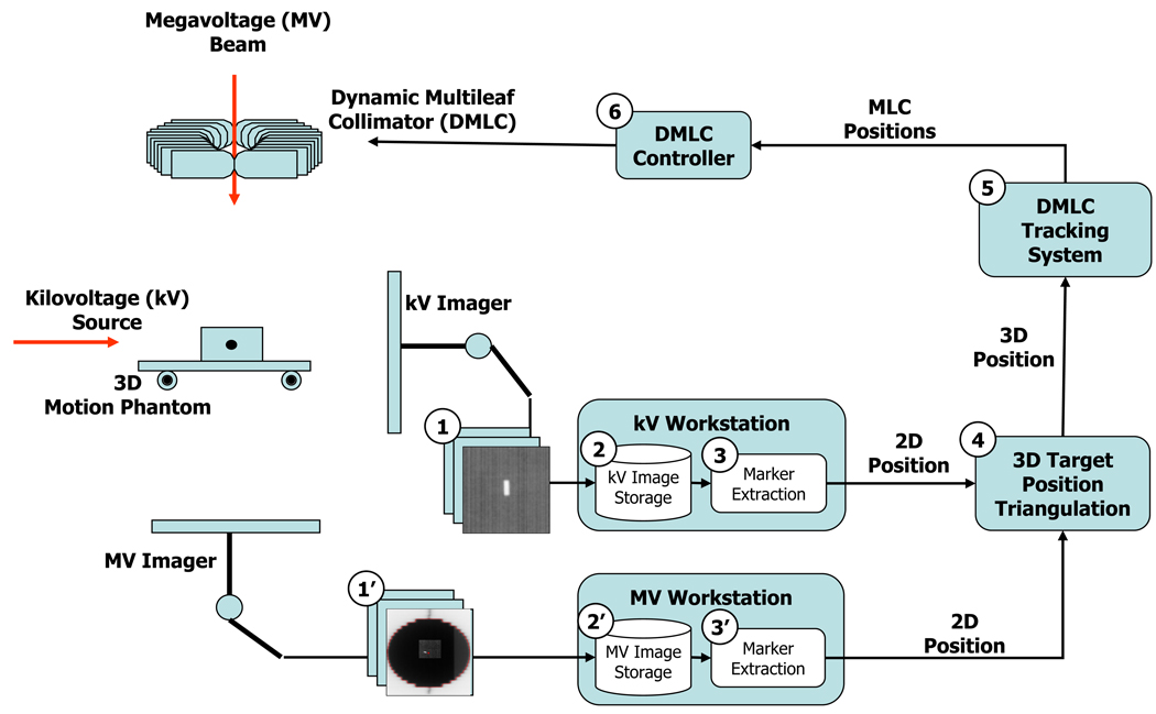
A real-time DMLC tracking system (6) integrated with a target tracking system using simultaneous kV and MV imaging of a fiducial marker is shown schematically in Figure 1. A Varian Trilogy system (Varian Medical Systems, Palo Alto, CA) was employed with the integrated tracking system.
Fig. 1.
Flowchart of X-ray image-guided real-time DMLC tracking.
A gold marker (3 mm in length and 1 mm in diameter), embedded in a Styrofoam block, was placed on a 3D motion platform (17), which was programmed to produce an elliptical motion with 2 cm in the superior–inferior (SI) direction and 1 cm in the left–right (LR) direction at 10 cycles per minute.
The marker was simultaneously, but independently imaged by an On-Board kV imaging system and a PortalVision AS-1000 MV imaging system. Both kV and MV image acquisition were performed in service mode using IAS3Monitor software (Varian Medical Systems, Palo Alto, CA), which allows auto saving of the images on the hard disk as well as changing imaging frequency. The image resolution was 1024 × 768.
MV images were obtained continuously with the synchronized scan mode. In this mode, the detector readout was performed between MV beam pulses to reduce artifacts. The frame rate of MV imaging was variable depending on the MV beam energy and dose rate, but limited to a maximum of 9 frames per second (fps). For the irradiation conditions used in the present study, 6 MV at 300 MU/min, the frame rate of the MV imaging was 6.7 fps with 0.75 MU per frame (or 150 ms exposure time).
At the same time, the kV images were acquired continuously in the fluoroscopic scan mode with the exposure conditions of 55 kV, 40 mA, and 12 ms; these conditions were optimized to yield the best contrast for the marker with the MV beam on. The degradation of kV image quality due to MV beam scatter was solved by moving the kV detector further away from the isocenter at the source-to-imager distance (SID) of 180 cm. Although the maximum frame rate of kV imaging in the fluoroscopy scan mode was 15 fps, accumulated delays of image saving above 11 fps were observed. For consistency, the kV imaging frequency was reduced to 6.7 fps to match that of the MV imaging.
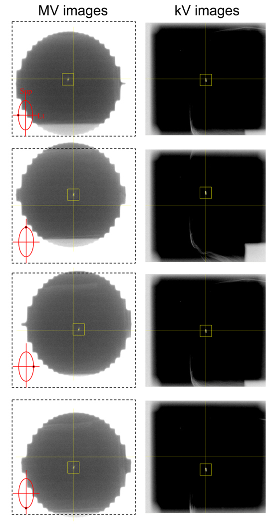
Immediately after an acquired kV (or MV) image was saved on the kV (or MV) workstation, an in-house marker tracking program read the image and extracted the projected marker position using a template-matching algorithm. This program extracts the marker position on the image that gives the maximum correlation with a template image. The template image of the 15×15 pixels surrounding the marker was selected from an image acquired before tracking started. To speed up the segmentation process, the search area was confined to a 41×41-pixel region centered at the computed marker position in the preceding image. No attempt was performed for sub-pixel matching. An example of a series of kV/MV image pairs acquired for tracking the marker in elliptical motion is shown in Figure 2.
Fig. 2.
Example of a series of (left) megavoltage (MV) and (right) kilovoltage (kV) image pairs acquired during the elliptical motion of the marker by vertical MV and horizontal kV imaging. On MV images with marker locations as insets, the dash-lined box with central cross was also displayed to guide the MV beam isocenter. The centers of MLC apertures were seen to be lagging behind the marker due to the time delay from image acquisition to MLC adjustment.
After segmentation, the marker tracking program sent the computed two-dimensional (2D) marker position to the DMLC tracking computer via Ethernet. When the DMLC tracking system received a projected position, it read the current gantry angle information via communication with the linac and tagged it on the projected position. The DMLC tracking system determined the 3D marker position by computing the position that had the minimum distance from both ray lines formed by a pair of kV/MV-projected 2D positions with their projection angles. This triangulation was performed using the latest pair of kV/MV positions every time a new kV or a new MV position became available. Therefore, the triangulation error could increase as the imaging time interval and/or the motion speed increases.
Finally, the required leaf positions were computed to facilitate repositioning of the MLC aperture to match the updated 3D marker position and were then communicated to the MLC controller (Millennium 120-leaf MLC, Varian Medical Systems, Palo Alto, CA), which actuated the mechanical leaf motion of the MLC at every 50-ms interval. The maximum leaf speed of the MLC is known to be approximately 3.5 cm/sec (18). In addition, the MLC controller is configured to assert beam-hold interruptions when any leaf is more than 0.5 cm from the requested position.
Calibration of kV/MV imager and Static Positioning Accuracy
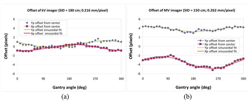
To utilize the orthogonal kV/MV imager pair as a 3D target-positioning guide for beam delivery, the MV beam isocenter should be projected at the origin of the imagers (defined as the center pixel of the imagers) irrelevant to gantry rotation. Any offset of the center pixel of each imager relative to the MV beam isocenter results in beam-delivery positioning errors. These offsets can be caused by several reasons, including misalignment of imager, or gantry sagging. For each imager, any offset was determined and corrected as a function of gantry angle.
To begin calibration, the MV beam isocenter was determined by the pixel coordinates of the MV imager by acquiring two MV images of an asymmetric field at inverted collimator angles of 90° and 270° for four principal gantry angles (0°, 90°, 180°, and 270°). This was accomplished using the calibration method described by Sharpe et al. (19). Next, the gold marker was located at the MV beam isocenter, and a pair of kV/MV images was acquired at every 10-degree gantry rotation from 0° to 360° with a SID of 150 cm and 180 cm for the MV and kV imagers, respectively. The marker position relative to the center pixel of each imager was fitted to a sinusoidal form as a function of gantry angle and used for correcting the offset of each imager.
The geometrical accuracy of determining stationary 3D marker positions was evaluated by positioning the marker at 27 static 3D positions in a 3×3×3 lattice pattern with 10-mm separation. At each location, horizontal kV and vertical MV images were acquired, and the 3D location of the marker was calculated and compared to the known value.
The static positioning accuracy with gantry rotation was also evaluated by analyzing triangulated 3D positions of the stationary marker at the MV beam isocenter during 360-degree arc beam delivery.
Time Delay and Dynamic Positioning (Tracking) Accuracy
X-ray image-guided DMLC tracking was performed during AP beam delivery. The 3D motion platform was programmed to move the marker horizontally in elliptical motion with a motion range of 2 cm in the SI direction, 1 cm in the LR direction, and a period of 10 cycles per minute. The range and speed of the elliptical motion was empirically chosen to avoid beam-hold interruption during tracking. The gold marker in the elliptical motion was tracked by simultaneous kV/MV imaging at 6.7 fps. The collimator was rotated so that MLC leaves moved parallel to the SI motion.
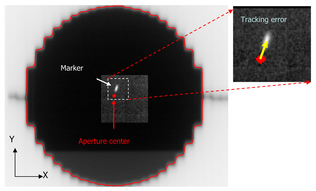
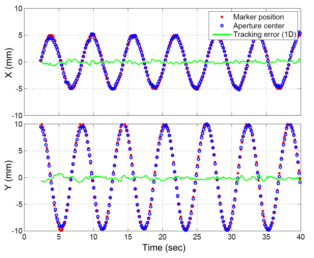
The tracking error was quantified as the distance between the marker position and the MLC aperture center, as measured through the MV images acquired during tracking (Fig. 3). The marker position determined by the marker tracking program during the tracking experiment was used for this purpose. To determine the MLC aperture center on each MV image, the edge curve of the MLC field was segmented and then fitted to a circle with center and radius as fit parameters using linear-squares estimation. The intensity threshold for the edge detection was adjusted so that the estimated radius was equal to the known 5-cm radius of the circular aperture.
Fig. 3.
Example of an MV image obtained during the same experiment as Figure 2. The distance between the marker position and the center of the circular aperture represents the tracking error.
The time delay from image acquisition to MLC adjustment was estimated by the phase shift from the marker position trajectory to the aperture center trajectory, as fitted to sinusoidal functions in the x and y directions. To investigate individual contributions to the total time delay, timestamps at major tracking steps, such as at the beginning and end of image reading, marker segmentation, and triangulation, were logged and analyzed.
To overcome the time delay, a modified linear adaptive prediction with the estimated time delay (20) was applied to further tracking experiments for quantifying tracking error and dosimetric analysis.
Dosimetric Impact
To evaluate dosimetric effects of tracking, film dosimetry was performed with Kodak EDR2 films in three different scenarios: static target; moving target without tracking; and moving target with tracking.
The film was sandwiched between 1-cm thick acrylic slabs and placed on the top of the marker-embedded Styrofoam block that was attached to the end of the arm of the motion platform. For each case, a film was irradiated by 300 MU using 6-MV photon AP beams. The same elliptical motion was used for the target motion. During film exposure, MV images were also acquired to investigate distributions of geometric error, as described above.
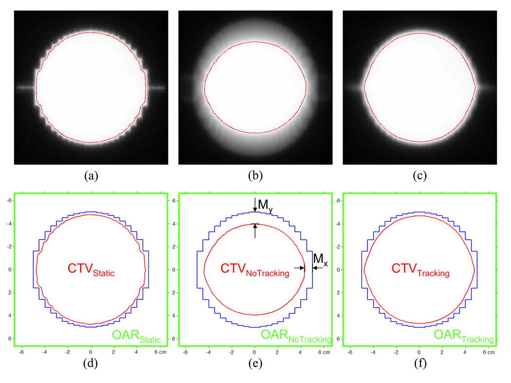
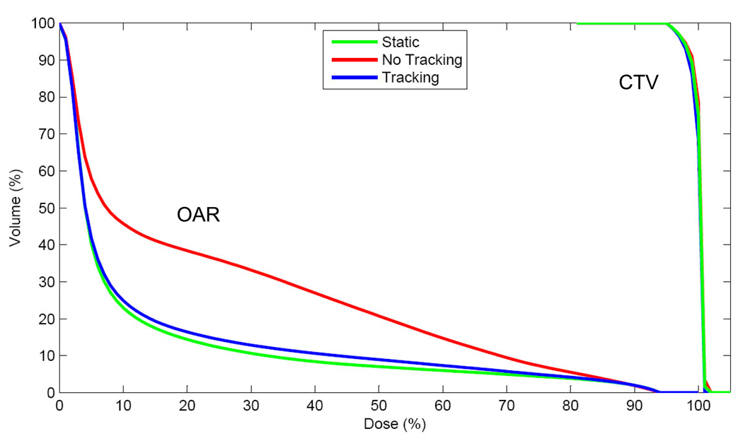
Assuming that in each case the 10-cm MLC aperture was adequate for covering its clinical target volume (CTV) with 95% dose, the V95 region was segmented and considered to be the CTV. Its area was computed, and the reduction relative to the area of MLC aperture was compared. Its geometrical extent to the beam edge was also computed as an indicator of margins. Furthermore a region outside of CTV and confined within a square of 13×13 cm2 was termed an organ-at-risk (OAR). Dose-volume histograms of both CTV and OAR for each case were computed.
In addition, two films with moving target were registered with the film of the static target, and a gamma evaluation analysis (21) was performed with 3% dose difference and 3-mm distance-to-agreement criteria.
RESULTS
Calibration of kV/MV imager and Static Positioning Accuracy
Figure 4 shows the offsets of the kV/MV imager with gantry rotation, along with the sinusoidal calibration curves.
Fig. 4.
Offsets of kV and MV imager as a function of gantry angle with respect to the MV beam isocenter, along with sinusoidal fits. SID stands for source-to-imager distance.
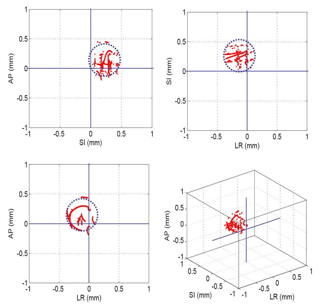
The geometric error of determining 27 static marker positions was 0.3 ± 0.1 mm in 3D. As shown in Figure 5, static 3D position estimation with gantry rotation showed similar results. Static positioning accuracy is important, because any errors in this process will manifest themselves as tracking errors. The 3D position estimation during gantry rotation provides a simple, yet accurate way to align the marker at the MV beam isocenter. By shifting the marker to the estimated mean offset, the error of the marker alignment can be easily eliminated.
Fig. 5.
The 3D positions of the stationary marker at the MV beam isocenter determined by kV/MV images during the arc delivery. The marker was aligned at the isocenter by acquiring anterior–posterior MV and left-lateral kV images. The mean offset in each direction from the isocenter, indicated by the center of dotted circle, was caused by the uncertainty of this alignment process. The radius of the dotted circle, ~± 0.25 mm (1 pixel), represents the uncertainty of marker extraction.
Time Delay and Tracking Accuracy
The time delay estimated by the phase shift in each direction ranged from ~435 to 455 ms. Further analysis with time stamping on the tracking log files showed that the total time delay was caused by the following: image acquisition (~200 ms), image handling time of saving and reading (~150 ms), image processing for marker segmentation and triangulation (~50 ms), and MLC adjustment (~50 ms) in sequence. The large contributions from image acquisition (~200 ms) and image handling time (~150 ms) delineate clearly what must be focused on to improve the current implementation.
Figure 6 shows trajectories of the marker and the center of the MLC aperture in each direction on the MV images during the AP beam delivery. The tracking error was 0.9 ± 0.5 mm. Without tracking, the error was expected to be 7.7 ± 1.7 mm.
Fig. 6.
Trajectories of the marker positions and the aperture centers on MV images with tracking error. X, Y means the horizontal and vertical directions on the MV images, and the Y direction coincides with the superior-inferior direction.
Dosimetric Impact
Figure 7 shows dose distributions of the 10-cm circular MLC aperture for static, no tracking, and tracking. In each case, the region covered by more than 95% dose (red lines in Fig. 7) was defined as CTV, with the assumption that the MLC aperture is designed to cover each CTV with 95% dose. As summarized in Table 1, reduction of CTV with no tracking was 76.2%, compared with CTV for static, and could be significantly mitigated to 97.2% with tracking. Without tracking, additional margins of 4.5–8 mm were required to cover the elliptical motion. These margins could be reduced to 0.8–1.0 mm with tracking, thereby reducing the dose to the surrounding normal tissue. The dose–volume histogram of OAR shows significant differences between no tracking vs. tracking, as shown in Figure 8.
Fig. 7.
Dose distributions of the 10-cm circular MLC aperture (blue) for (a) static, (b) no tracking, and (c) tracking, along with the definitions of CTV, OAR, and margins (d–f) in each case. Assuming that in each case the 10-cm circular MLC aperture was designed to cover its CTV with 95% dose (red), V95 was defined as CT V, while the OAR was defined as the outer region of CTV bound to a square of 13×13 cm2.
Table 1.
Margins, clinical target volume (CTV) reductions, and mean organ-at-risk (OAR) doses for static target, moving target without and with tracking. Note that the margins for the static target are due to the penumbra, σp.
| Static | No tracking | Tracking | |
|---|---|---|---|
| MarginX (mm) | |||
| Total (excluding σp) | 3.4 | 7.9 (4.5) | 4.3 (0.9) |
| MarginY (mm) | |||
| Total (excluding σp) | 2.5 | 10.5 (8.0) | 3.3 (0.8) |
| CTV reduction compared to area of MLC aperture (%) | 88.4 | 67.5 | 86.2 |
| CTV reduction compared to CTVstatic (%) | 100 | 76.2 | 97.2 |
| Mean dose (%) of OAR | 12.3 | 24.3 | 13.6 |
Fig. 8.
Dose-volume histogram of CTVs and OARs for static, no tracking, and tracking.
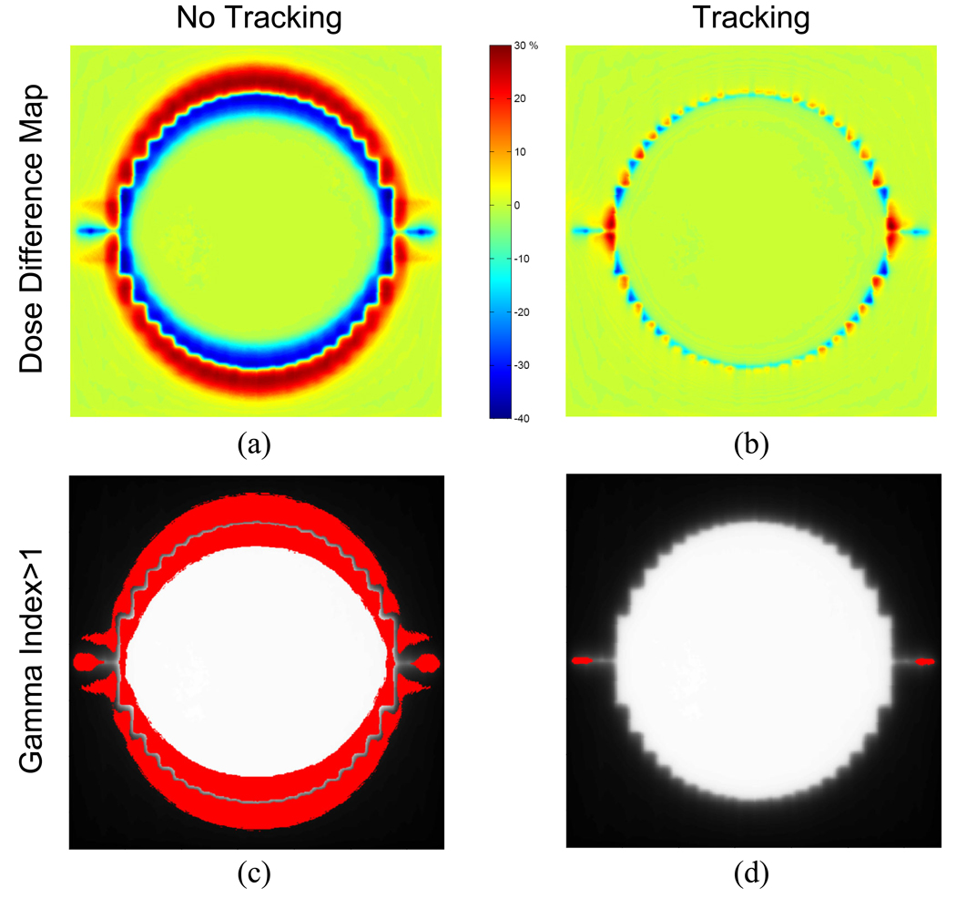
Figure 9 shows dose difference maps obtained by subtracting dose distributions of a static target from dose distributions of a moving target with and without tracking. With these maps, the gamma tests were performed. The percentage of points exceeding the acceptance criteria of 3% dose difference within 3mm distance was 0.2% with tracking and 22.5% without tracking.
Fig. 9.
Dose difference maps computed by subtracting the dose distributions of the static target from the dose distributions of the moving target (a) without tracking, (b) with tracking, as well as gamma test results with gamma index >1 shown in red for (c) without tracking and (d) with tracking.
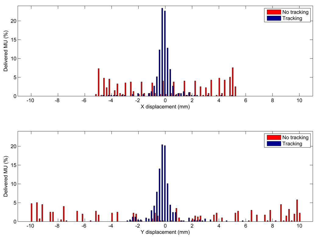
The dosimetric benefit with tracking over no motion management is reduced as the range of motion decreases and/or the speed of motion increases. Figure 10 shows the distribution of target-positioning errors with and without tracking, measured using the MV images acquired during the film irradiation. Without tracking, the errors distribute widely over the range of motion and have peaks at the end of range, which can be expected due to the probability density function of the elliptical motion. These errors could become close to Gaussian distribution with tracking. With tracking, most of the errors larger than 5 mm (5% of the total MU) occurred at the treatment onset when the MLC attempted to catch up with the target motion.
Fig. 10.
Distribution of target-positioning errors with and without tracking for the elliptical motion in the (a) x and (b) y directions measured using MV images acquired during the film irradiation.
DISCUSSION
In this study, we firstly demonstrated an entire tracking system, from marker-based target monitoring with kV/MV imaging to DMLC beam tracking, by incorporating online feedback of kV/MV imaging information into a clinical treatment machine. The method utilizes the kV/MV imaging systems already available on clinical treatment machines, thus provides an easy implementation for monitoring intrafraction tumor motion.
Here, we only used open-beam apertures to avoid blocking of the marker by the MLC on MV images. Use of multiple markers and/or monoscopic estimation of the 3D position utilizing a priori motion information is future work for intensity-modulated fixed/rotational therapy with tracking (22).
The main limitation of the current prototype is the relatively large time delay. One of main contributions is the image acquisition process (~200 ms). The lack of direct communication between each imaging system and the marker extraction program in the current prototype added a further time delay of ~150 ms. These time delays could be reduced through engineering efforts, such as direct memory access of image data by the segmentation program and/or reading of a reduced image region of interest only. An alternative to reduce the time delay is a hybrid tracking system such as the Synchrony system (Accuracy, Inc., Sunnyvale, CA), in which a simpler and faster external surrogate signal is used for estimating target position, and occasional X-ray imaging is used to build an internal/external correlation model (13). After all these efforts, any residual time delay could be mitigated with a suitable prediction algorithm (23–25). Experimental studies without the prediction algorithms (results not shown) yielded geometric errors of 3.6 ± 0.9 mm due to the total time delay of ~450ms. The error was reduced to 0.9 ± 0.5 mm when using a prediction algorithm.
A number of issues still need to be addressed to ensure that this technology is safe and effective for clinical use. First, new quality assurance (QA) protocols need to be developed based on the accumulated clinical experiences from other real-time tracking systems, such as the Synchrony system (13) and the real-time tumor tracking system (14) developed by Mitsubishi Electronics Co. (Tokyo, Japan). Here, kV/MV images, containing spatial information about tumor and OARs with irradiated field during treatment, will play important roles for QA as well as for record and verify purposes. In addition, the implanted marker-based tracking has the following limitations: 1) possible migration of the fiducial marker from the implanted position, 2) possible deformation of the tumor during radiation therapy, 3) risk of pneumothorax, and 4) lack of knowledge about the relationship between the marker and the OARs. The first two limitations can be reduced by using 3 or 4 fiducial markers around the tumor. The others may require more general approaches, such as intensity based tracking without markers with fluoroscopy (26) or fast MRI scan (27).
The maximum speed of some tumors (28) can exceed the finite velocity constraints of current MLC systems, indicating that beam holds will be necessary when using current generation MLCs for tumor tracking. The beam delivery efficiency for the elliptical motion in this work was 95%. However, the median tumor speed (28) is well below the velocity constraints indicating that a strategy to pause the beam during such motion would be appropriate without lengthening the treatment time significantly.
CONCLUSION
For the first time, combined kV/MV image-guided real-time DMLC tracking has been demonstrated. The static positioning accuracy is ~0.3 mm. For the large elliptical target motion used in this study, the average geometric error was less than 1 mm, and the dosimetric error was negligible. Though the current prototype showed a relatively large time delay (~450 ms), the method is promising for intrafraction motion management.
ACKNOWLEDGMENTS
The authors acknowledge financial support from the NIH/NCI (P01CA116602 and R01CA93626) and Varian Medical Systems. We particularly thank Herbert Cattell of Varian for engineering support with the MLC control. We also thank the anonymous reviewers whose comments and experimental suggestions greatly improved the manuscript and Devon Murphy for editing this manuscript.
Footnotes
Publisher's Disclaimer: This is a PDF file of an unedited manuscript that has been accepted for publication. As a service to our customers we are providing this early version of the manuscript. The manuscript will undergo copyediting, typesetting, and review of the resulting proof before it is published in its final citable form. Please note that during the production process errors may be discovered which could affect the content, and all legal disclaimers that apply to the journal pertain.
Conflicts of Interest Notification:
Per R. Poulsen has financial support from Varian Medical Systems, Alex Sloutsky is an employee of Varian Medical Systems and Paul J. Keall has financial support from the NIH/NCI (P01CA116602 and R01CA93626) and Varian Medical Systems.
REFERENCES
- 1.Grills IS, Yan D, Martinez AA, et al. Potential for reduced toxicity and dose escalation in the treatment of inoperable non-small-cell lung cancer: a comparison of intensity-modulated radiation therapy (IMRT), 3D conformal radiation, and elective nodal irradiation. Int J Radiat Oncol Biol Phys. 2003;57:875–890. doi: 10.1016/s0360-3016(03)00743-0. [DOI] [PubMed] [Google Scholar]
- 2.Hugo G, Tenn S, Agazaryan N. An evaluation of intrafraction motion-induced error for fractionated IMRT delivery. Medical Physics. 2003;30:1470–1470. [Google Scholar]
- 3.Schwarz M, Van Der Geer J, Van Herk M, et al. Impact of geometrical uncertainties on 3D CRT and IMRT dose distributions for lung cancer treatment. International Journal of Radiation Oncology Biology Physics. 2006;65:1260–1269. doi: 10.1016/j.ijrobp.2006.03.035. [DOI] [PubMed] [Google Scholar]
- 4.Jiang SB. Radiotherapy of mobile tumors. Seminars in Radiation Oncology. 2006;16:239–248. doi: 10.1016/j.semradonc.2006.04.007. [DOI] [PubMed] [Google Scholar]
- 5.Keall PJ, Mageras GS, Balter JM, et al. The management of respiratory motion in radiation oncology report of AAPM Task Group 76. Med Phys. 2006;33:3874–3900. doi: 10.1118/1.2349696. [DOI] [PubMed] [Google Scholar]
- 6.Keall PJ, Cattell H, Pokhrel D, et al. Geometric accuracy of a real-time target tracking system with dynamic multileaf collimator tracking system. International Journal of Radiation Oncology Biology Physics. 2006;65:1579–1584. doi: 10.1016/j.ijrobp.2006.04.038. [DOI] [PubMed] [Google Scholar]
- 7.Sawant A, Venkat R, Srivastava V, et al. Management of three-dimensional intrafraction motion through real-time DMLC tracking. Medical Physics. 2008;35:2050–2061. doi: 10.1118/1.2905355. [DOI] [PMC free article] [PubMed] [Google Scholar]
- 8.Gierga DP, Brewer J, Sharp GC, et al. The correlation between internal and external markers for abdominal tumors: Implications for respiratory gating. International Journal of Radiation Oncology Biology Physics. 2005;61:1551–1558. doi: 10.1016/j.ijrobp.2004.12.013. [DOI] [PubMed] [Google Scholar]
- 9.Beddar AS, Kainz K, Briere TM, et al. Correlation between internal fiducial tumor motion and external marker motion for liver tumors imaged with 4D-CT. International Journal of Radiation Oncology Biology Physics. 2007;67:630–638. doi: 10.1016/j.ijrobp.2006.10.007. [DOI] [PubMed] [Google Scholar]
- 10.Balter JM, Wright JN, Newell LJ, et al. Accuracy of a wireless localization system for radiotherapy. Int J Radiat Oncol Biol Phys. 2005;61:933–937. doi: 10.1016/j.ijrobp.2004.11.009. [DOI] [PubMed] [Google Scholar]
- 11.Sawant A, Smith RL, Venkat RB, et al. Geometric accuracy and latency of an integrated 4D IMRT delivery system using real-time internal position monitoring and dynamic MLC tracking. International Journal of Radiation Oncology Biology Physics. 2008;72:S27–S28. [Google Scholar]
- 12.Berbeco RI, Jiang SB, Sharp GC, et al. Integrated radiotherapy imaging system (IRIS): design considerations of tumour tracking with linac gantry-mounted diagnostic x-ray systems with flat-panel detectors. Physics in Medicine and Biology. 2004;49:243–255. doi: 10.1088/0031-9155/49/2/005. [DOI] [PubMed] [Google Scholar]
- 13.Schweikard A, Shiomi H, Adler J. Respiration tracking in radiosurgery. Medical Physics. 2004;31:2738–2741. doi: 10.1118/1.1774132. [DOI] [PubMed] [Google Scholar]
- 14.Shirato H, Shimizu S, Kitamura K, et al. Four-dimensional treatment planning and fluoroscopic real-time tumor tracking radiotherapy for moving tumor. International Journal of Radiation Oncology Biology Physics. 2000;48:435–442. doi: 10.1016/s0360-3016(00)00625-8. [DOI] [PubMed] [Google Scholar]
- 15.Mao WH, Riaz N, Lee L, et al. A fiducial detection algorithm for real-time image guided IMRT based on simultaneous MV and kV imaging. Medical Physics. 2008;35:3554–3564. doi: 10.1118/1.2953563. [DOI] [PMC free article] [PubMed] [Google Scholar]
- 16.Wiersma RD, Mao WH, Xing L. Combined kV and MV imaging for real-time tracking of implanted fiducial markers. Medical Physics. 2008;35:1191–1198. doi: 10.1118/1.2842072. [DOI] [PMC free article] [PubMed] [Google Scholar]
- 17.Malinowski K, Lechleiter K, Hubenschmidt J, et al. Use of the 4D Phantom to Test Real-Time Targeted Radiation Therapy Device Accuracy. Medical Physics. 2007;34:2611. [Google Scholar]
- 18.Wijesooriya K, Bartee C, Siebers JV, et al. Determination of maximum leaf velocity and acceleration of a dynamic multileaf collimator: Implications for 4D radiotherapy. Medical Physics. 2005;32:932–941. doi: 10.1118/1.1876581. [DOI] [PubMed] [Google Scholar]
- 19.Sharpe MB, Moseley DJ, Purdie TG, et al. The stability of mechanical calibration for a kV cone beam computed tomography system integrated with linear accelerator. Medical Physics. 2006;33:136–144. doi: 10.1118/1.2143141. [DOI] [PubMed] [Google Scholar]
- 20.Srivastava V, Keall P, Sawant A, et al. Accurate prediction of intra-fraction motion using a modified linear adaptive filter. Medical Physics. 2007;34:2546–2546. [Google Scholar]
- 21.Low DA, Dempsey JF. Evaluation of the gamma dose distribution comparison method. Medical Physics. 2003;30:2455–2464. doi: 10.1118/1.1598711. [DOI] [PubMed] [Google Scholar]
- 22.Poulsen PR, Cho B, Langen K, et al. Three-dimensional prostate position estimation with a single x-ray imager utilizing the spatial probability density. Physics in Medicine and Biology. 2008;53:4331–4353. doi: 10.1088/0031-9155/53/16/008. [DOI] [PubMed] [Google Scholar]
- 23.Murphy MJ, Dieterich S. Comparative performance of linear and nonlinear neural networks to predict irregular breathing. Physics in Medicine and Biology. 2006;51:5903–5914. doi: 10.1088/0031-9155/51/22/012. [DOI] [PubMed] [Google Scholar]
- 24.Ren Q, Nishioka S, Shirato H, et al. Adaptive prediction of respiratory motion for motion compensation radiotherapy. Physics in Medicine and Biology. 2007;52:6651–6661. doi: 10.1088/0031-9155/52/22/007. [DOI] [PubMed] [Google Scholar]
- 25.Ruan D, Fessler JA, Balter JM. Real-time prediction of respiratory motion based on local regression methods. Physics in Medicine and Biology. 2007;52:7137–7152. doi: 10.1088/0031-9155/52/23/024. [DOI] [PubMed] [Google Scholar]
- 26.Cui Y, Dy JG, Sharp GC, et al. Robust fluoroscopic respiratory gating for lung cancer radiotherapy without implanted fiducial markers. Phys Med Biol. 2007;52:741–755. doi: 10.1088/0031-9155/52/3/015. [DOI] [PubMed] [Google Scholar]
- 27.Koch N, Liu HH, Starkschall G, et al. Evaluation of internal lung motion for respiratory-gated radiotherapy using MRI: Part I--correlating internal lung motion with skin fiducial motion. Int J Radiat Oncol Biol Phys. 2004;60:1459–1472. doi: 10.1016/j.ijrobp.2004.05.055. [DOI] [PubMed] [Google Scholar]
- 28.Shirato H, Suzuki K, Sharp GC, et al. Speed and amplitude of lung tumor motion precisely detected in four-dimensional setup and in real-time tumor-tracking radiotherapy. International Journal of Radiation Oncology Biology Physics. 2006;64:1229–1236. doi: 10.1016/j.ijrobp.2005.11.016. [DOI] [PubMed] [Google Scholar]


