

Abstract
Surfactants at air/water interfaces are often subjected to mechanical stresses as the interfaces they occupy are reduced in area. The most well characterized forms of stress relaxation in these systems are first order phase transitions from lower density to higher density phases. Here we study stress relaxation in lipid monolayers that occurs once chemical phase transitions have been exhausted. At these highly compressed states, the monolayer undergoes global mechanical relaxations termed collapse. By studying four different types of monolayers, we determine that collapse modes are most closely linked to in-plane rigidity. We characterize the rigidity of the monolayer by analyzing in-plane morphology on numerous length scales. More rigid monolayers collapse out-of-plane via a hard elastic mode similar to an elastic membrane, while softer monolayers relax in-plane by shearing.
I. Introduction
For decades, lipid surfactants assembled at air/water interfaces (Langmuir monolayers) have been studied due to their technological importance, biological relevance, and physical curiosity and complexity. Industry uses surfactant technology in cleaning products, oil extraction and drug delivery systems because surfactants stabilize interfaces between unlike phases. Biologically, surfactants are indispensable in helping us breathe by stabilizing the large air/water interface in the lungs.1-3 Physically these ultra thin layers provide attractive models for studying phase transitions, critical phenomena and nanoscale mechanics.4-6
Technological and biological interfaces are commonly subjected to changes in area. For example, as you breathe in and out, the surface area of your lungs changes. If the interface is covered in surfactant, such area changes will place mechanical stress on the surfactant layer. Since interfacial stability relies on surfactant stability at the interface, there is substantial interest in understanding how the surfactant layer responds to stress.7-10
The most studied forms of stress relaxation in surfactant layers are phase transitions.5,6,11,12 As interface area is changed, the surface density of surfactant will change. Eventually, the surfactant will undergo a thermodynamic phase transition from some lower density phase to a higher density one when the area is reduced through compression or vice versa for area expansion. The two-dimensional phase behavior of surfactant monolayers is extremely rich, and similar to their 3D counterparts it depends on molecular structure, temperature and density.4-6
Interfacial area can only be reduced to a point where surfactant molecules resist packing into a higher density state due to the hard limit dictated by molecular cross-sectional area. Further compression from this point can compromise the stability of the interface and lead to surfactant ‘collapse’.13 Collapse is broadly defined as the movement of surfactant molecules from the interface into the bulk.13,14 Different monolayers collapse at different area densities; the exact density depends on many factors including composition, phase behavior and even rate of compression.7,8,15
Surfactant collapse can be thought of as a mechanical transition of state. It occurs when phase transitions have been exhausted as a means of relaxing compressive stresses and in-plane stresses build up in the surfactant covered interface. These stresses eventually relax by out-of-plane deviation. The particular mechanism of these deviations can be divided into two categories: fluid-like response and solid-like response. The fluid-like response occurs through a nucleation and growth mechanism16-19 where surfactant flows into the subphase making vesicles, disks, and tubes underneath the monolayer.8,20
More than fifty years ago, H. E. Ries first observed the solid-like response with the formation of trilayered structures on top of the monolayer.21 He postulated a simple model of monolayer weakening, folding, bending, and collapse to give the observed multilayers.22 This work was the first to invoke a plate model to study surfactant collapse. Compress a plate and eventually it loses stability and buckles out of plane.23,24 The parallel between monolayer collapse and elastic stability of interfacial membranes has recently been explored.25-27 These models attempt to explain the particular structure of solid-like collapse involving experimentally observed large folds into the subphase.7-10 The main problem with our current understanding of solid-like collapse is a lack of criteria for folding. Defects have been invoked by many authors to explain folding.25,28-33 In particular, potential defect sites have been explored in biphasic lipids, where material properties of the two phases are mismatched. Theoretical calculations showed that at the interface of such mismatched phases, a mechanical instability develops;28,29 moreover, experiments corroborated that folding occurred in these systems when phase separation was present and did not occur upon heating above the critical point of the system.8 However, more recently, folding was observed in single component monolayers despite the lack of phase separation.9,10,25
In this paper, we experimentally explore a more universal criterion for monolayer folding: in-plane rigidity. We show that the folding transition can be suppressed by macroscopic in-plane shearing. Moreover, our work shows that despite the presence of defects previously believed to be sites of fold formation,8,25,28,29 folding does not occur without in-plane resistance to shear.
We provide a set of predictive criteria that allows us to determine the mode of collapse at area densities far below the critical collapse density. This set of criteria relies on the evolution of the monolayer surface as visualized by microscopy, a standard method used in monolayer work. It provides for the first time a method by which the mode of collapse can be predicted prior to actually reaching collapse.
For our systems, we have chosen to study two sets of lipid monolayers that are chemically different, but related by their relative material properties. Model lung surfactant mixtures are commonly studied for their collapse behavior, because it is believed the mode of collapse is key in determining proper biological function.2,3 One of the systems we study is a model lung surfactant composed of dipalmitoylphosphatidylcholine (DPPC), palmitoyloleoylphosphatidylglycerol (POPG), and a surfactant peptide. The collapse and phase behavior of the pure lipid system 7 : 3 DPPC : POPG has been extensively studied at Chicago both experimentally as well as theoretically.8,28,29,34 In the present work, we look at how the collapse behavior of this monolayer is perturbed upon the addition of a truncated lung surfactant peptide B. Secondly, we study a two-component model containing ganglioside GM1 and zwitterionic lipid, DPPC. As the ratio of DPPC : GM1 within the monolayer is changed, the phase behavior, and hence the in-plane rigidity of the layer are systematically altered, and consequently, so is the response of the monolayer to lateral stress.
II. Experimental procedures
A. Lipids, peptides, subphase and superphase
DPPC, POPG, and ganglioside GM1 were obtained in powder form from Avanti Polar Lipids, Inc. (Alabaster, AL) and used without further purification. The lipids were dissolved in chloroform (HPLC grade, Fisher Scientific, Pittsburgh, PA) or chloroform containing 10% methanol (HPLC grade, Fisher Scientific, Pittsburgh, PA) in the case of GM1 to make 5 mg ml−1 stock solutions. The synthetic lung surfactant peptide B (SP-B 9–25), a seventeen amino acid peptide with the sequence WLCRALIKRIQAMIPKG, was prepared with either an Applied Biosystems (Foster City, CA) 431A solid-phase peptide synthesizer or a Protein Technologies Symphony/Multiplex SPPS (Tucson, AZ) synthesizer using an FMOC strategy35,36 (double-coupling, 2 × 45 min). The peptide was then cleaved using modified Reagent K (88.9% trifluoroacetic acid (TFA), 4.4% triisopropyl silane (TIS), 2.2% thioanisol and 4.4% water), precipitated by addition of ice-cold diethyl ether and the precipitate collected by centrifugation. The crude peptide was then purified with preparative reversed-phase HPLC.2 After purification, the predicted molecular mass for the peptide was confirmed by MALDI-TOF mass spectrometry using an ABI Voyager RP-RBT2 reflection time-of-flight mass spectrometer (Applied Biosystems, Foster City, CA). Lipid and lipid—peptide mixtures were prepared in several molar ratios: 7 : 3 DPPC : POPG, 7 : 3 DPPC : POPG with 10 wt% SP-B 9–25, 8 : 2 DPPC : GM1, and 5 : 5 DPPC : GM1. The solutions were diluted to obtain spreading solutions of concentration 0.1 mg ml−1. The fluorescent probe used for visualization at 0.5 mol% with fluorescence microscopy was Texas Red 1,2-dihexadecanoyl-sn-glycerol-3-phosphoethanolamine (TR-DHPE) (Molecular Probes, Eugene, OR). For all Langmuir trough experiments, the subphase was ultrapure water (resistivity 18 MΩ cm) processed by a Milli-Q ultra-purification set-up (A-10 gradient, Millipore, Bedford, MA). When experiments were performed on monolayers containing POPG, ultra high purity argon (Airgas, Chicago, IL) was used to minimize oxidative damage to the unsaturated oleoyl chain; in all other cases, the superphase was air.
B. Instrument setup
Details of the Langmuir trough set-up have been discussed previously.8 Briefly, the setup consisted of a custom-made Teflon trough equipped with two Teflon barriers whose motions were precisely controlled by a pair of translational stages (UTM100, Newport, Irvine, CA) for symmetric compression or expansion of monolayers at the air/water interface. A stationary Wilhelmy balance (Riegler and Kirstein, Berlin, Germany) is used to measure surface pressure. As the surface area is reduced (compression) or increased (expansion), the change in surface pressure is monitored. We find reasons to question the interpretation of the Wilhelmy plate measurement as the true surface pressure when the monolayer is rigid (see Appendix A). In light of this, even though we continue to refer to “surface pressure” in the paper, this should be interpreted with the arguments of Appendix A in mind.
Subphase temperature was maintained within 0.5 °C of the desired temperature with a homebuilt temperature control station composed of thermoelectric units (Marlow Industries, Dallas, TX) joined to a heat sink held at 20 °C by a Neslab RTE-100 water circulator (Portsmouth, NH). A piece of resistively-heated cover glass (Delta Technologies, Dallas, TX) was placed over the trough and held at a slightly higher temperature to suppress evaporative losses, minimize convective currents, and prevent condensation of water on the microscope objective.
The trough assembly was fixed to a custom-built microscope stage to allow simultaneous fluorescence microscopy (FM) with a 20X extra-long working distance objective (Nikon Y-FL, Fryer Company, Huntley, IL). A high-pressure mercury lamp (Osram Sylvania, Danvers, MA) was used for fluorescence excitation and the emitted light was gathered with a dichroic mirror/filter cube (Nikon HYQ Texas Red, Fryer Company, Huntley, IL). Images from the fluorescence microscope were collected at a rate of 30 frames s−1 using a CCD camera (Stanford Photonics Inc., Palo Alto, CA), and recorded on a Sony digital video cassette with a recorder (B + H Photo-Video, New York, NY). This assembly permits monolayer morphology to be observed over a large lateral area while isotherm data are obtained. The entire assembly is mounted on a vibration isolation table (Newport, Irvine, CA) and controlled by a custom software interface written using LabView 6.1 (National Instruments, Dallas, TX).
C. Isothermal compression measurements
For each monolayer experiment, 80 ml of water were used for the subphase and temperature was maintained at 25 °C for DPPC—POPG, and 30 °C for DPPC—GM1 mixtures. These temperatures were chosen to minimize the material property differences within each series. The surface balance was calibrated to the value of surface tension of pure water for a given temperature. The lipid monolayer was spread at the air/water interface by drop-wise addition of the spreading solution and allowed to equilibrate for 20 min to ensure evaporation of organic solvent. The barriers were then compressed with a linear speed of 0.1 mm s−1 and isotherm data in the form of surface pressure Π (mN m−1) versus area per lipid molecule A (Å2 molecule−1) were collected at 1 second intervals until the system reached its compression limit. The surface was imaged continuously with fluorescence microscopy throughout the compression.
D. Atomic force microscopy
Higher resolution imaging of the various monolayers was obtained with atomic force microscopy (AFM) by transferring them from the air/water interface to a solid mica substrate (Ted Pella, Inc. Redding, CA). Lipid monolayers from the Langmuir trough were transferred onto mica substrates by an inverse Langmuir—Shaefer transfer technique similar to that in Lee et al.37 A substrate was placed in a stainless steel apparatus with a surrounding 2 mm high machined knife edge, and the entire setup placed at the bottom of the trough where it remained submerged in the subphase throughout the compression isotherm. At the desired Wilhelmy pressure, the subphase was slowly aspirated from the trough to lower the subphase level and the knife edge eventually cut the monolayer as the surface height lowered, preserving the monolayer morphology at the desired surface tension. Drilled holes in the bottom of the steel piece allowed water to exit the chamber completely until the monolayer was deposited on the mica surface. Monolayer morphology before, during, and after transfer was monitored with FM to ensure that the domain structures were not perturbed by the transfer process.
Lipid monolayers transferred to mica substrates were imaged using a Multimode Nanoscope IIIA scanning probe microscope (Digital Instruments, Santa Barbara, CA) with a Type J scanner in contact mode in air. Silicon nitride tips NP-S (Veeco Probes, Woodbury, NY), with a nominal spring constant of 0.32 N m−1 were used; the surfaces of the tips were decontaminated by UV generated ozone before sampling (PSD-UV Surface Decontamination System, Novascan, Ames, IA).
III. Results
A. Domain packing
Fluorescence images acquired at different surface pressures provide micron level resolution of the monolayer’s surface morphology. As mentioned in the introduction, the primary response of Langmuir monolayers to compression is phase transitions. The four different monolayer systems investigated here, 7 : 3 DPPC : POPG, 7 : 3 DPPC : POPG with 10 wt% SP-B 9–25, 8 : 2 DPPC : GM1, and 5 : 5 DPPC : GM1, were all compressed from initially high surface areas (low surface pressures) where the lipids were in a gas (G) phase. Compression of the gas phase eventually leads to a first order phase transition into the liquid expanded (LE) phase where the fluorescent probe is homogeneously mixed with the lipids, and FM imaging shows a homogeneously bright field. Fig. 1 shows the surface pressure vs. area isotherms for the different systems. The transition from G/LE coexistence to LE phases is accompanied by the initial increase in surface pressure called the isotherm lift-off point (see Fig. 1).
Fig. 1.

Surface pressure versus area isotherms: A. 7 : 3 DPPC : POPG (black solid line) and 7 : 3 DPPC : POPG with 10 wt% SP-B 9–25 (red dashed line); B. 8 : 2 DPPC : GM1 (black solid line) and 5 : 5 DPPC : GM1 (red dashed line). The black arrows indicate the start of the LE to C phase transition, and the green arrows indicate the end of the transition which is defined as the rigidity onset point for each system.
Since all the systems in our study are below their melting points, the lipids undergo a second phase transition from the LE phase to the condensed (C) phase at a higher pressure. On the isotherms the coexistence of the LE and C phases appears as a plateau, with the start indicated by black arrows and the end of the transition by green arrows in Fig. 1. The condensed phase has a crystalline lattice structure that excludes the bulky Texas Red probe making this phase appear dark in comparison with the LE.38,39
Fig. 2 and 3 show fluorescence images of the four systems at several different surface pressures. The condensed phase develops via a nucleation and growth mechanism where C domains appear homogeneously across the field of view and grow into quasi-circular structures. All the fluorescence images show the characteristic morphology of the so-called phase separated monolayer with dark C domains surrounded by a continuous brighter phase. The images are taken at surface pressures beyond which domain size no longer changes, a point we term the rigidity onset and define as the end of the LE/C phase transition plateau (see green arrows in Fig. 1).
Fig. 2.

Fluorescence images and corresponding S(q) for systems that collapse by folding. Images A. through C.: 7 : 3 DPPC : POPG compressed to 30, 50, and 70 mN m−1, respectively; images D. through F.: 8 : 2 DPPC : GM1 at the same surface pressures. The images on the left are the fluorescence image of the monolayer, while the corresponding images on the right are the 2D Fourier power spectra of the fluorescence autocorrelation (the structure factor S(q)).
Fig. 3.

Fluorescence images and corresponding S(q) for systems that do not collapse by folding. Images A. through C.: 7 : 3 DPPC : POPG 10 wt% SP-B 9–25 compressed to 30, 50, and 70 mN m−1, respectively; images D. through F.: 5 : 5 DPPC : GM1 at the same surface pressures. The images on the left are the fluorescence images of the monolayer, while the corresponding images on the right are the 2D Fourier power spectra of the fluorescence autocorrelation (the structure factor S(q)).
To compare and study the global domain packing structure and its evolution with compression, we calculate a structure factor (S(q)) for each image (appearing to the right of the corresponding image in Fig. 2 and 3). The structure factor describes the spatial distribution of regions showing high (bright continuous region) and low (dark C domains) levels of fluorescence. The spatial distribution information is represented by intensity values of individual pixels in the FM images. The images are filtered to remove high-frequency noise associated with CCD imaging as well as low frequency variations resulting from nonuniform illumination. An autocorrelation of the filtered image is then computed to indicate the rate of decay in positional correlation between bright and dark regions in the fluorescence images, and a 2D Fourier power spectrum is created to give the structure factor provided in the figure.
To better understand the information contained in S(q), consider a hypothetical monolayer where C domains are packed on a perfect hexagonal lattice with each domain having six nearest neighbors. In this case, S(q) would show six bright spots arranged at the vertices of a hexagon. From the center to vertex distances (q-spacing), inter-domain distances (d-spacings) can be calculated, d = 2π/q.40 Since the domains in this example are constrained to a perfect lattice, the d-spacing will be the same in every spatial direction, or the system has both long-range translational and orientational order. If we relax the packing constraint such that the domains no longer sit perfectly on the hexagonal lattice yet maintain six nearest neighbor packing (a discussion of this for our systems is given below), the S(q) spots begin to smear into a ring.40 Inter domain d-spacing can still be extracted from this type of powder spectra by measuring the center to ring distances.
The first row of images in Fig. 2 and Fig. 3 show that at Π = 30 mN m−1, all four monolayers have a symmetric packing structure. The C domains in the 7 : 3 DPPC : POPG monolayer have a d-spacing of 16 mm which does not change with the addition of peptide. The 8 : 2 DPPC : GM1 monolayer has larger domains with a d-spacing of 45 μm, which decreases by a factor of 2 with the addition of more GM1 indicating that addition of GM1 reduces the size of the domains. The overall shape of S(q)at this lower pressure indicates a symmetric close-packed structure in all four systems.
We further compressed the monolayers to collapse pressures and monitored the surface morphology. Interestingly, the domain packing structure evolved differently in the four systems. In 7 : 3 DPPC : POPG and 8 : 2 DPPC : GM1, the domain packing symmetry is preserved. Fig. 2B and C show 7 : 3 DPPC : POPG at 50 mN m−1 and 70 mN m−1 respectively. Examining S(q) shows that at collapse pressure the domains are more closely packed in the horizontal direction parallel to compression (d-spacing of 11 μm) versus the vertical direction perpendicular to compression (d-spacing of 23 μm), however, there is preservation of the close packed hexagonal structure. The 8 : 2 DPPC : GM1 system (Fig. 2E and F) at higher pressures shows a greater resistance to lattice deformation indicated by no change in S(q) with compression. Both 7 : 3 DPPC : POPG and 8 : 2 DPPC : GM1 collapse by forming large folds into the subphase (movies of the collapsing monolayers are available in the ESI, see movie 1 and 2†).
Addition of peptide to 7 : 3 DPPC : POPG and increasing GM1 concentration in the second system leads to a symmetry breaking morphology transition at higher compressions. Fig. 3B and C show 7 : 3 DPPC : POPG with 10 wt% SP-B 9–25 at 50 mN m−1 and 70 mN m−1 respectively. The symmetric ring of intensity seen in S(q) at 30 mN m−1 that is indicative of a symmetric and close packed morphology is broken into two separate intensity bands at 50 mN m−1. Compression to collapse pressure of 70 mN m−1 leads to further definition of the bands and strengthening of the nodes separating them. This evolution of the structure factor indicates a significant rearrangement of domain packing. Indeed, examining the FM images directly (B and C), there is a noticeable lining up of domains parallel to the compression direction that is not present at the lower pressure (A). The same S(q) and FM image evolution is seen in the 5 : 5 DPPC : GM1 system (Fig. 3E and F).
To better understand the new structure factor, consider a hypothetical monolayer where long rectangular domains are lined up in horizontal stripes. Since within each stripe there is no change in intensity, the hypothetical d-spacing is zero causing a horizontal node to appear in the corresponding S(q).40 However, along the vertical direction, where there is intensity oscillation generated by the stripes, S(q) will show bands whose distance from the center gives the typical inter-stripe spacing. For 7 : 3 DPPC : POPG with 10 wt% SP-B 9–25 and 5 : 5 DPPC : GM1 at 70 mN m−1, the S(q) indicates that the domains are so tightly packed in the horizontal direction that nearest neighbors are not distinguished. These horizontal bands of domains are separated from each other in the vertical direction by 16 μm and 22 μm in the two systems respectively.
The first appearance of this in-plane symmetry breaking or banding transition occurs at Π ≈ 40 mN m−1 for 7 : 3 DPPC : POPG with 10 wt% SP-B 9–25 and at a slightly higher surface pressure of around 55 mN m−1 for 5 : 5 DPPC : GM1 (data not shown). This process of domain realignment into bands is accompanied by a significantly different collapse response. These monolayers do not form folds. The only observable sign of collapse is near the trough barriers, where there are bright spots and lines indicating high dye concentration due to multilayered structures. One of the primary indicators of folding in monolayers besides direct visualization of folds is lateral motion (“jerking”) of the film at collapse34 (see ESI movies 1 and 2†). In the monolayers which undergo domain rearrangement, not only are folds not visualized, but no “jerking” motion is observed at collapse (see ESI movies 3 and 4†).
It was mentioned earlier that the ring of intensity seen with the lower pressure S(q) came from a powder like structure that develops as domains are no longer required to sit on a perfect hexagonal lattice. Considering again the model hexagonally packed monolayer, when packing constraints are relaxed, domains far enough apart may still have the same local packing (orientational symmetry is preserved) yet have lost their long-range positional order.40 The surface in this case will be divided into patches of close packed domains separated by grain boundaries. To give a sense of the heterogeneity in packing structure and the scale of the different hexagonal patches, we constructed Voronoi diagrams shown in Fig. 4 for the different FM images in Fig. 2 and Fig. 3. The Voronoi diagrams show the number of nearest neighbors for each domain. Gray indicates that the domain has six nearest neighbors, and so is hexagonally packed. The other colors indicate different numbers of nearest neighbors, the most common being the yellow—cyan pair, indicating a five—seven defect. Fig. 4A shows that at Π = 30 mN m−1, the 7 : 3 DPPC : POPG monolayer is dominated by large patches of gray separated by lines of yellow—cyan domains. These lines of defects in the hexagonal packing indicate grain boundaries where two patches of differently oriented hexagonal lattices come together. As the surface pressure is increased first to 50 and then to 70 mN m−1 (Fig. 4B and C, respectively) the number of non-gray, thus non-hexagonally packed domains increases. At Π = 70 mN m−1, defects appear to group together in higher order structures other than the lines observed at lower pressures. This shows that the lattice is becoming fundamentally different from a close packed hexagonal structure with grain boundaries. Recall that this is also seen by the elongation of the structure factor into an ellipse at the high pressures.
Fig. 4.

Images A. through C.: 7 : 3 DPPC : POPG compressed to 30, 50, and 70 mN m−1 respectively. Each image is the Voronoi construction of the corresponding FM image in Fig. 2A., B., and C. Gray domains each have six nearest neighbors, yellow domains five, cyan domains seven, orange domains eight, and green domains four. Images D. through F. are 7 : 3 DPPC : POPG 10 wt% SP-B 9–25 compressed to 30, 50, and 70 mN m−1, respectively.
The set of images in Fig. 4D—F are the Voronoi diagrams for 7 : 3 DPPC : POPG with 10 wt% SP-B 9–25. At the relatively low surface pressure of 30 mN m−1, Fig. 4D, there is little difference from the corresponding monolayer that folds (Fig. 4A). However, at the higher pressures, where the FM images show banding, and the structure factor shows a symmetry broken state, the Voronoi diagrams also show that the number of non-hexagonally packed domains is higher than in the corresponding 7 : 3 DPPC : POPG diagrams. Similarly, Fig. 4E and F show the non-hexagonal defects primarily organized into patches and not lines, meaning a fundamental change in domain packing occurs as the monolayer is compressed. This is to be expected given the symmetry broken structure factor for these monolayers.
All the monolayers studied undergo the same transitions from G to LE to C at low compression. Eventually all the systems have a similar composite morphology, dark C domains embedded in a bright continuous phase as seen by FM imaging. Despite morphological similarities at low compression, the monolayers respond differently upon further compression and then collapse differently. One group maintains the same surface morphology and eventually collapses by folding, while the other group undergoes a symmetry breaking morphological transition to horizontal bands of domains and does not exhibit folding. To say anything more about the different behaviors at higher compressions, we need to characterize the monolayer with a higher resolution technique. The difference between the two groups lies in the composition and corresponding material properties of the bright or continuous region, and AFM imaging of deposited monolayers probes this region with nanometre resolution.
B. AFM imaging
FM images capture different monolayer stress relaxation modes occurring on a roughly micron length scale. To understand the driving force of these different transitions on a more molecular level, atomic force microscopy was performed on each monolayer deposited on a solid mica support. These micrographs show monolayer morphology on a length scale two-orders of magnitude smaller than that of FM, allowing further insight about the material properties of the layer. Each monolayer was deposited at three different surface pressures, Π = 30, 50, 70 mN m−1 corresponding to pre-banding transition, post-banding transition, and the folding regime shown in Fig. 2 and Fig. 3, allowing the monolayer morphology to be monitored before and after the rigidity onset point.
Lipids within the C domains pack in a lattice type structure where the all-trans hydrocarbon chains of one lipid are in register with those of the neighboring lipids. In less ordered, more fluid phases, the hydrocarbon chains of lipid molecules have more space and therefore retain a greater amount of conformational freedom. When a biphasic (LE/C) single-component monolayer is deposited onto mica, the condensed domains are ∼0.7–0.9 nm taller than fluid lipids due to the difference in packing and tilt of the acyl chains.39,41 Since all monolayers examined in this paper are phase-separated at surface pressures of deposition, the height of numerous condensed domains can be used as a reference state. Any material that is lower in height than the C phase is more disordered in the monolayer.
AFM micrographs of 7 : 3 DPPC : POPG 10 wt% SP-B 9–25, a banding, non-folding monolayer at 30 mN m−1 (Fig. 5A and B), show a flower shaped C domain surrounded by a darker (lower in height by 0.8 nm) region which corresponds to the continuous bright phase between C domains visualized with FM. We define this bright phase between C domains as the “continuous matrix” to discern between fluidity determined by dye distribution within the monolayer as measured by FM and that seen via topographic mapping provided by AFM. In the scan shown in Fig. 5B, it is evident the continuous matrix is not uniform. The more fluid phase is peppered with small C domains. However, the area fraction of fluid phase within the continuous matrix is still greater than the C domains, rendering it less rigid.
Fig. 5.
AFM micrographs of 7 : 3 DPPC : POPG 10 wt% SP-B 9–25 (A. and B.) and 7 : 3 DPPC : POPG (C. and D.) at 30 mN m−1. Solid C domains are visible in all images as brighter colored regions; in A. the C domain appears as a flower shape. The LE area corresponding to the bright phase in fluorescence images (referred to as the continuous matrix) in A. and B. has a higher area fraction of fluid lipid than in C. and D. This indicates that DPPC—POPG with peptide (A. and B.) has a less well-packed disordered region compared to DPPC—POPG without peptide (C and D).
Atomic force micrographs of deposited 7 : 3 DPPC : POPG (folding) monolayers are depicted in Fig. 5C and D. In Fig. 5C, there are two C domains as defined by FM; part of each fills the upper right and lower left corners. The continuous matrix fills the area between these domains. In Fig. 5D, there is a C domain in the lower right corner. While the continuous lipid matrix in these images is also heterogeneous, the relative amount of lower height phospholipid corresponding to a more fluid, less rigid phase is much less compared to the banding monolayer containing the peptide (Fig. 5A and B). The C domains that are scattered in the continuous matrix of the monolayer are significantly larger, and dominate the matrix phase in Fig. 5C and D. Even at a surface pressure of 30 mN m−1 where there is no discernable difference between the FM images of the non-folding and folding monolayers in terms of domain arrangement or area fraction of bright, fluid lipid, AFM analysis indicates that monolayers which eventually undergo a banding transition (Fig. 5A and B) have a more fluid continuous matrix surrounding the condensed domains, while monolayers that fold at high surface pressure (Fig. 5C and D) have a more condensed continuous matrix.
When monolayers are deposited at a pressure past the rigidity onset, differences between banding and folding monolayers as defined by the area fraction of disordered lipid are even more readily apparent. Fig. 6A and B show AFM micrographs for monolayers that band (non-folding). Even at high Wilhelmy pressures, there remains a well-defined region of disordered lipids within the continuous matrix as is clear in the case of 5 : 5 DPPC : GM1 (Fig. 6A). In the lung surfactant case, the continuous matrix is filled with peptide aggregates (bright spots in Fig. 6B), which have been extensively studied.42 Nevertheless, a higher resolution scan (inset in Fig. 6B) reveals a clear co-existence of higher and lower phases in the lipid phase surrounding the aggregates similar to the GM1 case.
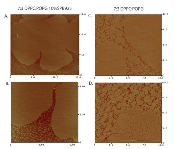
Fig. 6.

The first row shows AFM micrographs of deposited banding monolayers at high surface pressure (∼70 mN m−1): A. 5 : 5 DPPC : GM1, B. 7 : 3 DPPC : POPG 10 wt% SP-B 9–25 (inset is a zoom in of the black box in image B. showing a higher resolution image within the continuous matrix). The images show a persistence of height mismatched regions as those found at lower pressures (compare with Fig. 5). Notable in the peptide case is the presence of peptide aggregates (nanosilos) appearing as bright spots, which have been explored in detail before.42 The second row shows deposited monolayers that eventually folded: C. 8 : 2 DPPC : GM1 and D. 7 : 3 DPPC : POPG. Notable is the absence of height mismatched regions. The deposited layers are of uniform height and it is difficult to distinguish between the C domains and the continuous matrix, unlike the images in the first row.
The second row of images in Fig. 6 shows AFM scans of monolayers that fold deposited at high pressures. In both systems, 8 : 2 DPPC : GM1 (Fig. 6C) and 7 : 3 DPPC : POPG (Fig. 6D), the microstructure present at lower pressures is gone. The monolayers are of one homogeneous height, indicating that the continuous matrix and C domains are equally rigid. This is in contrast to the monolayers that band and do not fold where microstructure of disordered lipid persists to high pressures.
IV. Discussion and conclusions
A. Interfacial inextensibility
In the introduction, we noted that monolayer collapse can be thought of as a mechanical transition of state. Namely, collapse represents the transition whereby the flat interface covered with surfactant molecules takes on some non-flat or out-of-plane geometry. The field of solid-like collapse has focused in particular on large scale undulations of the surfactant layer. In this work, we have studied such undulations (folds) and concluded that folding is dependent on in-plane rigidity.
By examining the condensed domain packing structure of different systems, we discovered a peculiar transition in biphasic monolayers that has not previously been reported. Two chemically distinct monolayers, 7 : 3 DPPC : POPG 10 wt% SP-B 9–25 and 5 : 5 DPPC : GM1, undergo a rearrangement of their domains from hexagonal packing at low pressures to form horizontal bands at higher pressures. These monolayers also show a commonality in that they do not fold. Corresponding monolayers 7 : 3 DPPC : POPG and 8 : 2 DPPC : GM1 do not undergo this domain rearrangement and fold as previously reported.8
In previous models, the elastic nature of monolayers was directly assumed. Ries was the first to phenomenologically describe a solid like monolayer in terms of an elastic membrane or plate.22 The weakening, bending, and folding idea was further explored using a modified plate equation and showed that monolayers should buckle with periodic undulations (wrinkles) much like elastic plates.24,26 However, elastic arguments at the time were unable to describe how a nanometre thick membrane deviated microns out of plane. Explicit calculations showed that thermal fluctuations were insufficient,33 and this fueled ideas that monolayers must have large structural defects at which collapse structures could nucleate.25,28-31,33
The difficulty with using defects as a nucleation site for folding in monolayers is their ubiquitous presence. At an angstrom level, lipid monolayers are much like crystalline powders with very short coherence lengths.39 The interfaces between different lipid nano-crystals have been invoked as possible sites of collapse initiation.31 However, every monolayer with short-range order will have such interfaces, but not all such monolayers collapse in the same manner. Therefore, larger structural defects are better candidates for nucleation sites. In two-component systems, such as the ones studied here, micron size defects exist in the form of interfaces between phase separated regions (LE/C interfaces). As noted in the introduction, there has been a theoretical description of the instability of these interfaces,28,29 which was then used to explain the appearance of folds in the 7 : 3 DPPC : POPG system.8 The defects were seen as necessary criteria due to the fact that heating these monolayers to a temperature where phase separation no longer existed suppressed folding.8 However, such heating would also change the rigidity of the system, and in fact 7 : 3 DPPC : POPG collapses like a fluid beyond its melting point.8 The critical role of large structural defects is further put to the test in single component monolayers, where no macroscopic defect sites have been found.9,10,25
In this paper, we show that the existence of defects (LE/C interfaces) is not a sufficient criterion for folding. All of our systems have phase separation, yet only some of them fold. The significance of these results is that in-plane rigidity influences out-of-plane collapse behavior. Rigidity and resistance to in-plane deformations allows the monolayer to fold out-of-plane, however, accessibility to in-plane relaxation suppresses the out-of-plane motion despite strong defects. The implication here is that monolayers must behave as elastic membranes capable of supporting an anisotropic shear stress to be able to undergo the sharply focused out-of-plane folding behavior. This conclusion, supported by our data in four different monolayer systems, indicates that monolayer collapse can be thought of as a stress focusing phenomenon.43
It was recently shown that folding is a general mechanism of compaction for a supported elastic membrane.27 The two criteria for such localization are membrane inextensibility and compressive stress. A membrane can be thought of as inextensible if the forces needed to bend it are far weaker than those needed to stretch or shear it. This plays a central role in thin membrane elasticity23,24,43 and can commonly be seen by playing with a piece of paper. Try pulling on a piece of paper and it becomes quickly apparent that its resistance to stretching is enormous. Bending the same paper is trivial. The inextensible approximation becomes more accurate as a membrane becomes thinner, since in-plane stretching modes scale linearly with thickness h, while out-of-plane bending modes go as h3.23,24 For an ultra thin system like the lipid monolayer, bending is far easier than stretching (typical resistance to bending in lipid monolayers is on the order of 10 kT44). Even if a monolayer is not perfectly inextensible, stretching modes can quickly become far more costly than bending.
The second criterion mentioned above requires the monolayer to be under compression. Previous work was always done under the assumption that the monolayer was under a net tensile stress when collapse began.25,26,28,33 This assumption is based upon the Wilhelmy plate accurately measuring all stresses in the monolayer irrespective of monolayer fluidity or rigidity. In Appendix A, we show that the Wilhelmy measurement breaks down when the monolayer becomes rigid. Furthermore, we conclude that despite a positive tension measured at the plate, a rigid monolayer is under compression closer to the barriers.
We conjecture based upon the presented data and our conclusions that monolayer collapse should depend on the degree of inextensibility at the interface. For highly rigid monolayers where stretching and shearing modes are expensive in comparison to bending modes, folding can proceed via a general stress focusing mechanism for supported inextensible membranes.27 In systems where there is more in-plane fluidity, stretching may eventually become the dominant collapse mode. Similar arguments can further lead to an understanding of fluid collapse; since a fluid has minimal penalty for shearing, such a material can randomly leave the surface by flow at some critical pressure (in-plane stress) (see online supplemental video 5†). Though fluid membranes cannot support static shear stresses, they can develop viscous shear stress due to in-plane flows.43 It is also possible for fluid membranes, if compressed fast enough, to develop transient elastic-like behavior and fold (see online supplemental video 6†). Metastability and glass-like (dynamically trapped) behavior has previously been noted for fluid lipids similar to POPG.15,16
The arguments presented here can be used in a predictive way to determine collapse modes before the higher pressure collapse regime. In phase separated systems, the morphology of different phases should be monitored as we did here; in single component systems one could gain similar material property information by following surface embedded tracer molecules or particles. If the morphology rigidifies at some point or the tracers become immobilized, we propose this to be a significant criterion for the given monolayer to collapse by folding.
Thinking in terms of interfacial inextensibility brings some cohesion to the field of surfactant collapse. Surfactants at interfaces are unified by their geometry. Moreover, this geometry links them to other very diverse interfacial systems such as self-assembled nano-particles27,45,46 and even macroscopic powders.47-50 Despite their diversity in microscopic structure, upon compression, these systems show similar macroscopic behavior that can be explained using elastic arguments. Lipid films are unique in the respect that their composition and corresponding response can be so finely tuned. Systems with the same lipid components but differing in the presence of a protein or in the relative proportions of the lipids can have drastically different collapse behaviors.
B. Banding
AFM imaging of deposited monolayers at high pressures shows that in the more rigid, folding monolayers, there is no difference in height, and therefore fluidity, between the bright continuous matrix and the C domains. This lack of height difference indicates that the continuous phase and the C domains are both solid-like. In the case of the softer monolayers, which exhibit a banding transition, there is a 1 nm height difference between the C domains and disordered patches in the continuous phase, leading to the conclusion that the continuous matrix is more fluid and hence, softer, than the C disks. This is supported by the isotherms (Fig. 1) where the banding monolayers are seen to be more fluid with higher area per molecule at lift-off and a higher surface pressure at the phase transition to C domains.
The persistence of a softer, more disordered, phase throughout compression is key in understanding the banding transition. The banding can be viewed as a type of soft shear relaxation. It is possible because the C domains are able to move through the softer matrix. This movement is not possible in the more rigid monolayers.
The fact that there is strong correlation between band orientation and direction of compression indicates that the system is responding to the compressive stress coming from the barriers. Future experimental and theoretical work will hopefully allow us to understand the precise nature of the in-plane stresses. One possibility includes in-plane flows being generated by surface tension gradients, arising from over-compression of the film near the barriers. In-plane flows would minimize shear stresses as the C domains form bands which give rise to channels along which the flows can proceed. Another possibility is to interpret the data from a perspective of granular materials. A granular system under stress commonly undergoes a stress induced anisotropy. This anisotropy leads to a percolating network of force chains in two dimensions.51 The bands could be interpreted as such a network.
Monolayer elasticity should be explicitly considered when looking at collapse. A hard elastic response leads to inextensible type behavior with folding out-of-plane; while a softer response allows for in-plane rearrangements which suppress out-of-plane folding.
Supplementary Material
Acknowledgements
We thank Enrique Cerda and Haim Diamant for valuable discussions. This work was supported in part by the University of Chicago MRSEC program of the NSF (DMR-0213745) and the US—Israel Binational Foundation (2006076). LP thanks the University of Chicago Medical Scientist Training Program for support. SLF is grateful for the support from the National Science Foundation Graduate Fellowship Program. KK acknowledges the support of an ICAM Post-Doctoral Fellowship. KYCL is grateful for support from March of Dimes (No. 6-FY07–357) and ICAM. Frans J. Walther and Alan J. Waring are supported by NIH grants HL 55534–10 and HL 92158–01. Two of the authors, LP and SLF, contributed equally to the experiments in this work.
V. Appendix A
The Wilhelmy plate is the standard method for monitoring interfacial tension in a Langmuir trough. It consists of a strip of water-wetting material attached to a force transducer hanging into the trough. The meniscus pulls down the strip with a force proportional to the net surface tension, i.e. the bare surface tension less the surface pressure of any adsorbed molecules. In a static, fluid monolayer, the surface pressure is uniform and unaffected by the geometry of the meniscus. Here we investigate whether the same is true when the monolayer is solid and transmits deviatoric stress. We investigate the effect of solidity on pressure in a simplified geometry and show that a small increase in pressure at the periphery leads to a weaker increase at the plate, the weakening being governed by the ratio of shear to bulk modulus.
The simplified system is a thin annular disk of outer radius R and inner radius a. The annulus represents the Wilhelmy plate; the outer radius represents the boundary of the Langmuir trough. We now decrease R slightly, thereby producing a (negative) radial displacement field u(r). This results in a radial strain γrr = ∂ru. Here positive strain indicates extension. The displacement also creates an azimuthal strain γφφ = u/r. Under uniform strain u(r) = αr and γrr = γφφ. With this radial symmetry the principal axes of the strain are evidently the r and φ directions. We suppose that the disk is made of isotropic elastic material, so that the strain gives rise to a proportional stress σ with the same principal axes.
| (1) |
The same elastic coefficients apply to principle strains in any direction: A accounts for stress along the same axis as the strain; B accounts for the stress arising from perpendicular strain. In a fluid, evidently A = B: every strain gives an isotropic stress. (We consider here only static stresses, which arise from compression.) We interpret σ as tensile stress, so that the A and B coefficients are positive.
It is useful to identify the geometric meaning of A/B. If we exert a radial stress but no azimuthal stress, the strains must evidently satisfy 0 = Aγφφ + Bγrr. Thus γφφ = −(B/A)γrr. The proportionality factor (B/A) is conventionally = known as the Poisson ratio ν.
The equilibrium conditions for stress are: ∂rσrr = 0 and νθσθθ = 0. Thus σrr must be independent of position. Using the expression for σrr in terms of strain, which in turn is given in terms of the displacement field, u(r), we find
| (2) |
As noted above, a particular solution to the equation is u = br. In order to satisfy the inner boundary condition u(a) = 0, we must include the homogeneous solution.
| (3) |
Integrating gives
| (4) |
We may combine the solutions to achieve u(a) = 0:
| (5) |
The hydrostatic strain is the sum of the principal strains: γrr + γφφ. Using the known displacement field u(r) above, we find
| (6) |
We have seen that fluid response means A = B or ν = 1. Here we see that although u(r) is affected by the fixed inner boundary, the hydrostatic strain is not. Thus as anticipated above, the stress is uniform in a liquid layer. In the solid case, the strain and stress are distorted near the inner boundary. The distortion falls off with distance with a power larger than unity. The power depends on the Poisson ratio of the material. The distortion reduces the stress near the inner boundary. Thus any sensor of this stress—i.e. surface pressure—would register a reduced effect of increased exterior compression.
In practice, neither the outer boundary nor the plate are radially symmetric. The shape of the outer boundary is likely not important, since the distortion found above falls off far from the plate. As for the plate itself, we expect the distortion to be concentrated at the two ends of the strip, where radial displacements are necessary. Still, it seems likely that a strip of width a has a comparable distortion for r > a as for a cylindrical “strip” of diameter a.
It appears from this simple analysis that Wilhemy plate measurements are distorted when the monolayer being measured has an elastic and non-fluid character. Taking the elastic distortion into account or removing it may change the interpretation of many current experiments on dense monolayers. That is, parts of the monolayer away from the plate may be under a compressive stress even if a positive surface tension is measured at the plate. Naturally, the distortion should die away if the non-fluid stress relaxes. Yet in many monolayers of interest, this relaxation is slow—slow enough that the orientation of the plate has clear effects on the Wilhemy force.
Footnotes
Electronic supplementary information (ESI) available: Fluorescence microscopy movies showing the different types of monolayer collapse modes. See DOI: 10.1039/b804611e
References
- 1.Piknova B, Schram V, Hall SB. Pulmonary Surfactant: Phase Behavior and Function. Curr. Opin. Struct. Biol. 2002;12:487. doi: 10.1016/s0959-440x(02)00352-4. [DOI] [PubMed] [Google Scholar]
- 2.Robertson B, Halliday HL. Principles of Surfactant Replacement. Biochim. Biophys. Acta. 1998;1408:346. doi: 10.1016/s0925-4439(98)00080-5. [DOI] [PubMed] [Google Scholar]
- 3.Zasadzinski JA, Ding J, Warriner HE, Bringezu F, Waring AJ. The Physics and Physiology of Lung Surfactant. Curr. Opin. Colloid Interface Sci. 2001;6:506. [Google Scholar]
- 4.Safran SA. Statistical Thermodynamics of Surfaces, Interfaces, and Membranes. Westview Press; Boulder Colorado: 2003. [Google Scholar]
- 5.Möhwald H. Phospholipid and Phospholipid—Protein Monolayers at the Air/Water Interface. Annu. Rev. Phys. Chem. 2001;41:441. doi: 10.1146/annurev.pc.41.100190.002301. [DOI] [PubMed] [Google Scholar]
- 6.Möhwald H. Surfactant layers at water surfaces. Rep. Prog. Phys. 1992;56:653. [Google Scholar]
- 7.Lipp MM, Lee KYC, Takamoto DY, Zasadzinski JA, Waring AJ. Coexistance of Buckled and Flat Monolayers. Phys. Rev. Lett. 1998;80(8):1650. [Google Scholar]
- 8.Gopal A, Lee KYC. Morphology and Collapse Transitions in Binary Phospholipid Monolayers. J. Phys. Chem. B. 2001;105:10348. [Google Scholar]
- 9.Ybert C, Lu W, Moller G, Knobler CM. Collapse of a Monolayer by Three Mechanisms. J. Phys. Chem. B. 2002;106:2004. [Google Scholar]
- 10.Ybert C, Lu W, Moller G, Knobler CM. Kinetics of phase transitions in monolayers: collapse. J. Phys.: Condens. Matter. 2002;14:4753. [Google Scholar]
- 11.Kaganer VM, Möhwald H, Dutta P. Structure and phase transitions in Langmuir monolayers. Rev. Mod. Phys. 1999;71:779. [Google Scholar]
- 12.McConnell HM. Structures and transitions in lipid monolayers at the air—water interface. Annu. Rev. Phys. Chem. 1991;42:171. [Google Scholar]
- 13.Andelman D, Brochard F, Knobler C, Rondelez F. Micelles, Membranes, Microemulsions, and Monolayers. Springer-Verlag; New York: 1994. [Google Scholar]
- 14.Evans DF, Wennerström H. The Colloidal Domain — Where Physics, Chemistry, Biology, and Technology Meet. 2nd edn Wiley-VCH; New York: 1999. [Google Scholar]
- 15.Yan W, Hall SB. Distribution of Coexisting Solid and Fluid Phases Alters the Kinetics of Collapse from Phospholipid Monolayers. J. Phys. Chem. B. 2006;110:22064. doi: 10.1021/jp056989z. [DOI] [PMC free article] [PubMed] [Google Scholar]
- 16.Smith RD, Berg JC. The Collapse of Surfactant Monolayers at the Air—Water Interface. J. Colloid Interface Sci. 1980;74:273. [Google Scholar]
- 17.Vollhardt D, Retter U. Nucleation in Insoluble Monolayers. 1. Nucleation and Growth Model for Relaxation of Metastable Monolayers. J. Phys. Chem. 1991;95:3723. [Google Scholar]
- 18.ollhardt DV, Retter U, Siegel S. Nucleation in Insoluble Monolayers. 2. Constant Pressure Relaxation of Octadeconic Acid Monolayers. Thin Solid Films. 1991;199:189. [Google Scholar]
- 19.Vollhardt D, Retter U. Nucleation in Insoluble Monolayers. 3. Overlapping Effect of the Growing Centers. Langmuir. 1992;8:309. [Google Scholar]
- 20.Nguyen TT, Gopal A, Lee KYC, Witten TA. Surface charge relaxation and the pearling instability of charged surfactant tubes. Phys. Rev. E. 2005;72:051930. doi: 10.1103/PhysRevE.72.051930. [DOI] [PubMed] [Google Scholar]
- 21.Ries HE, Kimball WA. Monolayer structure as revealed by electron microscopy. J. Phys. Chem. 1955;59:94. [Google Scholar]
- 22.Ries HE. Stable ridges in a collapsing monolayer. Nature. 1979;281:287. [Google Scholar]
- 23.Landau LD, Lifshitz EM. Theory of Elasticity. 3rd edn Pergamon, NY: 1986. [Google Scholar]
- 24.Timoshenko SP, Woinowsky-Kreiger S. Theory of Plates and Shells. 2nd edn McGraw-Hill Publishing Co; New York: 1964. [Google Scholar]
- 25.Lu W, Knobler CM, Bruinsma RF, Twardos M, Dennin M. Folding Langmuir Monolayers. Phys. Rev. Lett. 2002;89(14):146107. doi: 10.1103/PhysRevLett.89.146107. [DOI] [PubMed] [Google Scholar]
- 26.Millner ST, Joanny JF, Pincus P. Buckling of Langmuir Monolayers. Europhys. Lett. 1989;9:495. [Google Scholar]
- 27.Pocivavsek L, Dellsy R, Kern A, Johson S, Lin B, Lee KYC, Cerda E. Stress and Fold Localization in Thin Elastic Membranes. Science. 2008;320:912. doi: 10.1126/science.1154069. [DOI] [PubMed] [Google Scholar]
- 28.Diamant H, Witten TA, Gopal A, Lee KYC. Unstable topography of biphasic surfactant monolayers. Europhys. Lett. 2000;52:171. [Google Scholar]
- 29.Diamant H, Witten TA, Ege C, Gopal A, Lee KYC. Topography and instability of monolayers near domain boundaries. Phys. Rev. E. 2001;63:061602. doi: 10.1103/PhysRevE.63.061602. [DOI] [PubMed] [Google Scholar]
- 30.Saint-Jalmes A, Graner F, Gallet F, Houchmandzadeh B. Buckling of a Bidimensional Solid. Europhys. Lett. 1994;28:565. [Google Scholar]
- 31.Saint-Jalmes A, Gallet F. Buckling in a solid Langmuir monolayer: light scattering measurements and elastic model. Eur. Phys. J. B. 1998;2:489. [Google Scholar]
- 32.Saint-Jalmes A, Assenheimer M, Gallet F. Surface Tension and Compression Modulus Anisotropies of a Phospholipid Monolayer Spread on Water and on Formamide. J. Phys. Chem. B. 1998;102:5810. [Google Scholar]
- 33.Nikomarov ES. A Slow Collapse of a Monolayer Spread on an Aqueous Surface. Langmuir. 1990;6:410. [Google Scholar]
- 34.Gopal A, Belyi VA, Diamant H, Witten TA, Lee KYC. Microscopic Folds and Macroscopic Jerks in Lipid Monolayers. J. Phys. Chem. B. 2006;110(21):10220–10223. doi: 10.1021/jp0618983. [DOI] [PubMed] [Google Scholar]
- 35.Fields CG, Lloyd DH, McDonald RL, Ottenson KM, Nobel RL. HBTU activation for automated Fmoc solid-phase peptide synthesis. Peptide Res. 1991;4:95. [PubMed] [Google Scholar]
- 36.Waring AJ, Walther FJ, Gordon LM, Hernandez-Juviel JM, Hong T, Sherman MA, Alonso C, Alig T, Braun A, Bacon D, Zasadzinski JA. The role of charged amphipathic helices in the structure and function of surfactant protein B (SP-B) J. Pept. Res. 2005;66:364. doi: 10.1111/j.1399-3011.2005.00300.x. [DOI] [PubMed] [Google Scholar]
- 37.Lee KYC, Lipp MM, Takamoto DY, Ter-Ovanesyan E, Zasadzinski JA. Apparatus for the Continuous Monitoring of Surface Morphology via Fluorescence Microscopy during Monolayer Transfer to Substrates. Langmuir. 1998;14:2567. [Google Scholar]
- 38.Knobler CM. Seeing Phenomena in Flatland: Studies of Monolayers by Fluorescence Microscopy. Science. 1990;249:870. doi: 10.1126/science.249.4971.870. [DOI] [PubMed] [Google Scholar]
- 39.Frey SL, Chi EY, Arratia C, Majewski J, Kjaer K, Lee KYC. Condensing and Fluidizing Effects of Ganglioside GM1 on Phospholipid Films. Biophys. J. 2008;94:3047. doi: 10.1529/biophysj.107.119990. [DOI] [PMC free article] [PubMed] [Google Scholar]
- 40.Chaiken PM, Lubensky TC. Principles of Condensed Matter Physics. Cambridge University Press; UK: 2000. ch. 2. [Google Scholar]
- 41.Hollars CW, Dunn RC. Submicron Structure in L-alpha dipalmitoylphosphatidycholine Monolayers and Bilayers probed with Confocal, Atomic, and Near-field Microscopy. Biophys. J. 1998;75:342–352. doi: 10.1016/S0006-3495(98)77518-6. [DOI] [PMC free article] [PubMed] [Google Scholar]
- 42.Ding J, Doudevski I, Warriner HE, Alig T, Zasadzinski JA. Nanostructure Changes in Lung Surfactant Monolayers Induced by Interactions between Palmitoyloleoylphosphatidylglycerol and Surfactant Protein B. Langmuir. 2003;19:1539. [Google Scholar]
- 43.Witten TA. Stress focusing in elastic sheets. Rev. Mod. Phys. 2007;79:643. [Google Scholar]
- 44.Bourdieu L, Daillant J, Chatenay D, Braslau A, Colson D. Buckling of Polymerized Monomolecular Films. Phys. Rev. Lett. 1994;72:1502. doi: 10.1103/PhysRevLett.72.1502. [DOI] [PubMed] [Google Scholar]
- 45.Lin BH, Schultz DG, Lin XM, Li DX, Gebhardt J, Meron M, Viccaro PJ. Langmuir monolayers of gold nanoparticles. Thin Solid Films. 2007;515:5669. [Google Scholar]
- 46.Schultz DG, Lin XM, Li DX, Gebhardt J, Meron M, Viccaro PJ, Lin BH. Structure, wrinkling, and reversibility of Langmuir monolayers of gold nanoparticles. J. Phys. Chem. B. 2006;110:24522. doi: 10.1021/jp063820s. [DOI] [PubMed] [Google Scholar]
- 47.Basavaraj MG, Fuller GG, Fransaer J, Vermant J. Packing, Flipping, and Buckling Transitions in compressed Monolayers of Ellipsoidal Latex Particles. Langmuir. 2006;22:6605. doi: 10.1021/la060465o. [DOI] [PubMed] [Google Scholar]
- 48.Vella D, Aussillous P, Mahadevan L. Elasticity of an Interfacial Particle Raft. Europhys. Lett. 2004;68:212. [Google Scholar]
- 49.Subramaniam AB, Abkarian M, Mahadevan L, Stone HA. Non-spherical bubbles. Nature. 2005;438:930. doi: 10.1038/438930a. [DOI] [PubMed] [Google Scholar]
- 50.Kim DH, Costello MJ, Duncan PB, Needham D. Mechanical Properties and Microstructure of Polycrystalline Phospholipid Monolayer Shells: Novel Solid Microparticles. Langmuir. 2003;19:8455. [Google Scholar]
- 51.Geng J, Reydellet G, Clement E, Behringer RP. Green’s function measurements of force transmission in 2D granular materials. Physica D. 2003;182:274. [Google Scholar]
Associated Data
This section collects any data citations, data availability statements, or supplementary materials included in this article.