Abstract
Partially polyurethane-covered stent (PPCS) is proposed for the treatment of cerebral aneurysms. The PPCSs were observed to substantially modify the flow entering the aneurysm in a patient-specific aneurysm phantom (PSAP). These stents can act as flow modulators and the polyurethane (PU) membrane can provide a smooth scaffold for restoring the structural integrity of the diseased vessel. Partial coating of the stent aids in sealing only the entrance to the aneurysm while keeping the perforators around the aneurysm open and patent. Biocompatibility of the PU membrane was monitored using contact angle measurements to show that critical surface tension (CST) values remained in the thromboresistant range of 20–30 mN/m. Stent flexibility, stiffness, and pressure–diameter relationship showed no significant change after asymmetric PU film application. No delamination of the PU membrane from the stent was observed within the working strains of the stent. The flow modulating capability of the PPCS was monitored by intentionally orienting the stent to cover either the proximal or the distal regions along the neck of the PSAP. Time density curves (TDCs) compared the relative metrics of input rate, washout rate, residence time, and influx in the aneurysm before and after the stent placement.
Keywords: stents, polyurethane coatings, flow studies, mechanical properties, biocompatibility
INTRODUCTION
Endovascular treatment for intracranial aneurysms has evolved in the last two decades. At present, stent implantation into cerebral arteries is increasingly considered to aid in reconstructing cerebral arteries diseased with aneurysms.1 For this intervention, there is a need to further improve the technical capabilities of a stent in treating intracranial aneurysms especially in cases such as large-necked aneurysms. With the advent of 3D clinical imaging more accurate localization and geometry determination of aneurysms can be achieved, thus improving success in endovascular treatments. The numbers of medical devices such as coils and stents are increasing because a single endovascular device cannot be used to treat all varieties of aneurysms. Among recent researchers designing and investigating new devices and combinations of existing devices for treating aneurysms, Lanzino et al.2 treated eight patients with coils along with stents to prevent coil herniation into the parent vessel and two patients solely by stents. Greater than 90% aneurysm occlusion was achieved in patients treated by stent and coil placement as demonstrated on immediate postprocedural angiograms. In patients originally treated solely by stent placement, no evidence of aneurysm thrombosis was observed either immediately postprocedure or on follow-up angiographic studies performed 24 hours, 48 hours, and 3 months later, respectively. The authors also indicated limited clinical practice of aneurysm treatment by stent alone due to high porosity of currently available stents. Later Wanke et al.3 treated wide-necked intracranial aneurysms of four consecutive patients with flexible self-expanding neurovascular stents to create a bridging scaffold followed by endovascular placement of coils through the stent interstices. Most recently, Katsaridis et al.4 treated a patient’s anterior cerebral artery (ACA) aneurysm with a Neuroform2 stent (Boston Scientific/Target, Fremont, CA) that was successfully delivered into the parietal branch and covered the aneurysm orifice. Consequently, the aneurysm was uneventfully embolized. The desired results with complete or nearly complete occlusion of the aneurysms were found in all patients after combined stent–coil placements. To increase the therapeutic competence of the stent alone, Doerfler et al.5 used double stents to treat small, wide-necked aneurysms of the distal vertebral artery in two cases of patients in which one stent was placed inside another. In both the cases remarkable flow reduction in the aneurysm was observed by angiography, and complete occlusion was found after 7 days. The limited number of patients treated by this method and lack of control of permeability of the stents at the neck of the aneurysm lessens confidence in this method. In animal studies, Krings et al.6 deployed porous as well as covered stents into elastase-induced rabbit aneurysms. They found that the porous stents led to aneurysm occlusion in two of five aneurysms in the 1-month follow-up group, and four of five aneurysms in the 3-month follow-up group. They also found that covered stents led to a complete and stable aneurysm occlusion with only minimal proliferative carrier vessel wall changes. However, such fully covered stents cannot be used in humans because of the risk of blocking perforators that are located around the aneurysm. Rather than using a stent for holding coils in place, an asymmetric vascular stent (AVS) which consists of a low porosity patch microwelded on a highly porous stent was introduced by Rudin et al.7 They deployed asymmetric stents in elastomer vessel aneurysm phantoms performing both optical8 and radiological flow examination9 as well as in animal models.10–12 The authors concluded that asymmetric stents created potentially favorable flow alterations. In this modified stent, because the low porosity patch was made of steel, it also modified the stiffness of the stent when crimped on the balloon and could cause difficulty in navigation through the tortuous vessels of the neurovasculature. Most stents in current use are based on an open cell structure that is expandable, but this open-cell structure does not allow for a continuous and smooth neointimal formation. In order to promote homogenous neointima coverage of the vessel lumen, a continuous film rather than a mesh may be preferred.13 Unlike the functions of uniformly porous stents which act as holders for embolic materials such as coils during the treatment of aneurysms, the most important requirement for the choice of the film coating for the stents in this work is for blocking/modifying the flow going into the aneurysm while retaining a dynamically thromboresistant blood-contact film surface under physiological flow conditions consistent with the restoration of normal flow in the diseased artery. The changes in flexibility and hoop stress of the stent after the PU film coating on the stent are related to the predicted ease of navigation and placement of the stent. In minimally invasive treatments, the balloon- or self-expandable stent mounted on the distal end of the catheter is traversed through the tortuous curves of the blood vessels in the brain so as to place accurately the device at the neck of the aneurysm. Therefore, the flexibility of the stent is a very important parameter and any changes in it that might result from the addition of the PU film could drastically affect the method of treatment. Similarly, the pressure required to expand the Partially polyurethane-covered stent (PPCS) to its final diameter is a crucial factor in determining if the same balloon catheter can be used to effectively inflate the stent to its desired diameter at the desired location. Pressures applied to any cylindrical structure result in hoop stress or circumferential loading of the tube. A partial PU film encasing a stent should be radially and uniformly expandable and retain its integrity once expanded within the artery for its lifetime. Once the stent is expanded, the film has to retain its bond to the stent metal structure without fragments peeling off and potentially leading to ischemic stroke distal to the stent deployment site. Therefore, it was important to determine and evaluate the strength of adhesion of the membrane to the stent.
The current PPCS introduced in this work has polycarbonate-based PU deposited asymmetrically on a stent by using a solution dip casting technique. The PU elastomer ChronoFlex AR, a medical-grade polyurethane (PU) from Cardiotech International (Woburn, MA) chosen for this design was found useful in many biomedical applications because of the excellent combination of physical and mechanical properties (toughness, flexibility), coupled with relatively good biocompatibility and biostability.
MATERIALS AND METHODS
Polyurethane Coating
Chronoflex AR (a solution–grade, segmented, aromatic, polycarbonate-based PU), manufactured by Cardio Tech International (Woburn, MA), was chosen for the current study. This polycarbonate-based PU is reported to exhibit superior corrosion and stress cracking resistance under harsh environments (human body). It has an elongation of 500% and tensile strength of 57 MPa, and is considered ideal in applications requiring exceptional flexure endurance. The tensile strength of PU film is dependent upon the curing temperature. Below the soft segment glass transition temperature, PU is rigid. Above the hard segment glass transition/melting temperature; the material behaves as an amorphous cross-linked rubber. Between these two transition temperatures, the material behaves as a typical thermoplastic elastomer.13,14
Chronoflex AR is synthesized from MDI (diphenylmethane 4,4′-diisocyanate) and polycarbonate diol, followed by addition of a mixture of chain extenders and a molecular weight regulator, with the reaction carried out in dimethyl acetamide (DMAC) solvent. Chronoflex AR was supplied as a 22% solid solution in DMAC for solution casting.15
Dimethyl formamide (99.8%) was used as a cosolvent to further dilute (85:15, v/v) the 22% solid solution of Chronoflex AR before solution-based casting.
Stent Fabrication
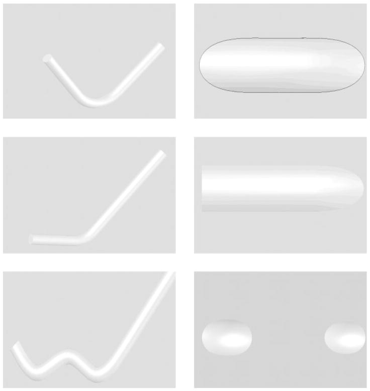
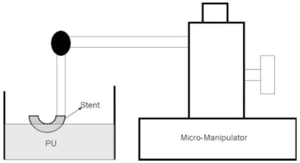
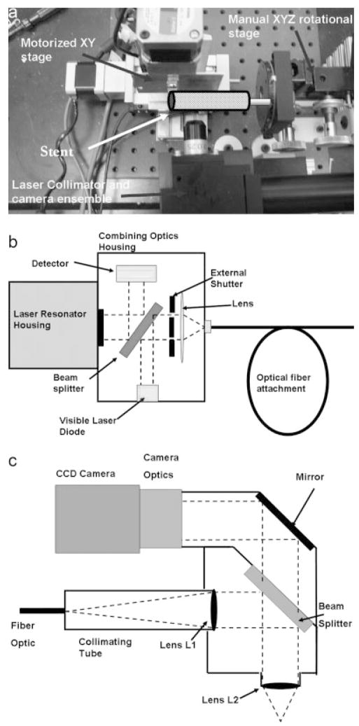
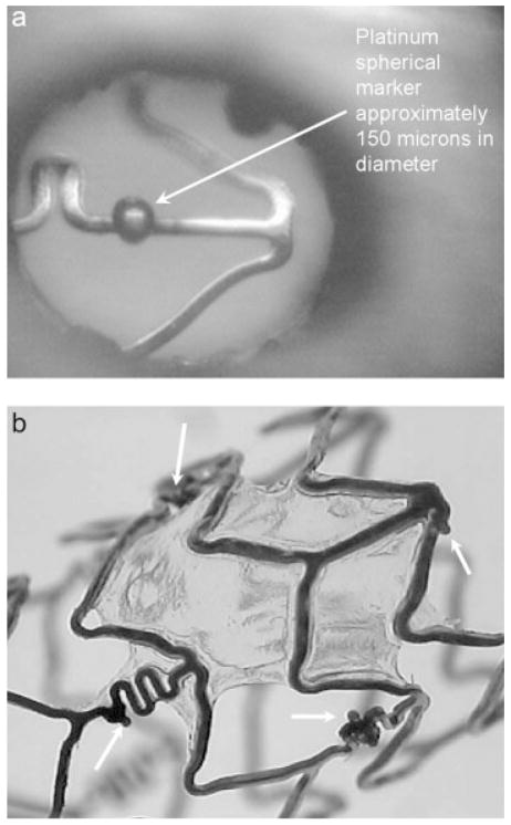
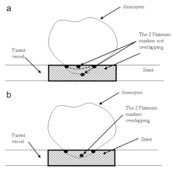
A balloon expandable 3.0 × 18.0 MultiLink Penta stent and 3.0 × 15.0 MultiLink Vision stent (Guidant Corp, Santa Clara, CA) were used for the current research. The stents were expanded during the process of modification to install the PU coating and crimped back on to the balloon delivery catheter prior to actual deployment and use. The uniform crimping procedure using a commercial desktop crimper (model no. SC 200, Machine Solutions, Flagstaff, AZ) assured that the stent cells retained the originally designed shape. Glass mandrels were bent at various curvatures and the expanded stents were slightly crimped onto the straight portions of the mandrels by the crimper before being slid to the bent portions of the mandrels. The glass mandrels were bent to different geometrical configurations to obtain the PU membrane only in desired locations on each test stent for flow modulation. Some forms of glass mandrels used are shown in Figure 1. The shape and size of the patch was controlled by the depth of dipping and the angle of bend on the glass mandrel. The glass mandrel was sprayed with a polydimethyl-silicone release agent lubricant prior to solvent-based dip casting for easy release of PPCS once cured. Each curved glass mandrel along with the stent was only partially dipped in the PU solution at an angle as shown in Figure 2. The film thickness of the PU was controlled by applying different number of coats, achieved by multiple dipping of the stent. In most cases, the stent was dipped only once to obtain a film thickness between 30 and 50 micrometers. The depth of dipping was controlled by a manual micromanipulator (model no. M 325, World Precision Instruments Inc, Sarasota, FL) with a vertical dipping resolution of 10 micrometers. Then the stent along with the glass mandrel was transferred to a convection oven and cured at 80°C for 12 hours. The stent was then removed from the straight portion of the glass mandrel enabling the stent to resume its original unbent shape. The stent was then inspected to identify the edges and integrity of the PU membrane. Since the PU membrane was asymmetrically deposited on the stent and as the patch was to be aligned with the aneurysm neck to modulate the flow inside the aneurysm, radio-opaque marking was essential for radiographic image-based intervention. Therefore, the stent with the PU membrane was marked for radio-opacity with four platinum markers of 100–150 micrometers in diameter circumscribing the edges of the patch. The markers were attached by laser welding. The complete setup for this is shown in Figure 3. The laser was an Nd:YAG laser with emission in the infrared range of the spectrum. After the laser was produced in the resonator [Figure 3(b)], the beam was incident on a splitting mirror, and part of the beam was redirected toward a power sensor which controlled two safety shutters. A visible laser beam produced by a diode was combined with the main laser beam using a beam splitter. The resulting beam was redirected using an optical fiber cable to the collimator-camera ensemble [Figure 3(c)]. The collimator was used in combination with two lenses to reduce the welding spot size. By combining two different collimators and three different lenses we were able to obtain six different welding spot sizes ranging between 365 and 50 micrometers. In order to visualize the welding, a camera was added as shown in Figure 3(a). In this setup, the stent was held in microtweezers on an XYZ manual stage as shown in Figure 3(a). A platinum wire was wrapped around the struts and a laser light was focused resulting in a spherical-shaped platinum marker laser-welded on to the stent strut as shown in Figure 4. One problem with four markers is that in a side view taken with a C-arm X-ray machine, the side of the stent where the PU was located could not be determined accurately. Therefore a transverse view was also taken for orienting the patch to the neck as shown in Figure 5(a,b). In Figure 5(a), the dotted line indicates the hidden side of the PU patch in this view. In this figure, the two markers are not superimposed, indicating misalignment of the PU patch with respect to the neck of the aneurysm. In Figure 5(b), the patch is aligned accurately to seal the entrance to the aneurysm as the two platinum markers superimpose on each other and only three markers are seen in a radiographic image instead of four.
Figure 1.
Different mandrel configurations used and corresponding shapes of the patches on the stent.
Figure 2.
Stent fabrication setup.
Figure 3.
Laser setup. (a) Motorized and manual stages. (b) The laser resonator box. (c) Laser collimator and camera setup.
Figure 4.
(a) Platinum marker welded on a stent strut. (b) Platinum markers (white arrows) circumscribing the edges of the polyurethane patch.
Figure 5.
Method of alignment of PPCS to the aneurysm neck using platinum markers (a) misaligned and (b) aligned.
Contact Angle Measurements
This method was used to monitor the surface properties of the PU for its potential maintenance of biocompatibility during placement and use in the biological environment. Of particular concern was the prospect that surface properties might be adversely affected by mechanical strain imparted to the PU film during stent deployment. The wettability of the surface, which is a measure of surface energy, is often considered as a factor of biocompatibility of blood contacting implants.13 Wettability was determined by sessile drop measurements of 11 different polar and apolar liquids of known, premeasured liquid/vapor surface tensions. The liquids used were water (72.0 dynes/cm), glycerol (65.0 dynes/cm), formamide (58.0 dynes/cm), thiodiglycol (53.5 dynes/cm), methylene iodide (49.0 dynes/cm), 1-bromonaphthalene (45.0 dynes/cm), 1-methylnaphthalene (39.0 dynes/cm), dicyclohexyl (33.0 dynes/cm), n-hexadecane (27.5 dynes/cm), n-tridecane (26.0) dynes/cm, n-decane (24.0 dynes/cm). The instrument used to measure contact angles was a Ramé-Hart goniometer. This instrument included an adjustable table for mounting the sample. The sample was backlit and viewed using a telescope with rotating cross hairs and a protractor scale in the eyepiece. Each drop liquid placed on the substratum was viewed at a 10× magnification.
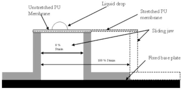
For a solid undergoing an isotropic strain, it may not deform isotropically, because some directions on the surface might deform more easily than others; therefore, the solid’s surface tension could vary with strain.13 The surface roughness may also change under strain due to the flattening of peaks and valleys, and it is well known that surface roughness has an influence on measured contact angles. As the PU film on the stent was cured at an intermediate diameter between crimped and expansion diameters, the membrane underwent a strain between 50% and 100%. A special jig was constructed, whose schematic is shown in Figure 6, to variably strain the PU film prior to contact angle measurements. The PU membrane was solution dip cast on a glass slide and cured at 80°C for 12 hours in a convection oven, reproducing the conditions for PU film formation on the glass-mandrel mounted stents. Two edges of the membrane were rigidly fixed on the jig’s 2 jaws. Then the sliding jaw was moved to strain the PU membrane and the contact angle measurements were made by placing the diagnostic liquid drops on the PU membrane in a sequence of diminishing premeasured surface tensions. The contact angle measurements were carried out at 0% strain and 100% strains to check for retained biocompatibility of the PPCS before and after expansion. The critical surface tension (CST) as defined by Zisman,16 is that for which the liquid has a surface tension equal to, or less than, the value required to completely wet and spread spontaneously on the surface. Prior work cited a correlation between the CST and thrombogenecity in which there is a region of optimum CST between 20 and 30 dynes/cm where biological interaction between the body and the biomaterial is minimum.8
Figure 6.
Straining jig.
Stent Flexibility and Pressure–Diameter Relationship Studies
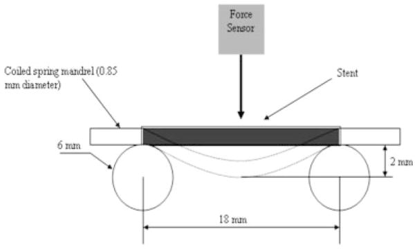
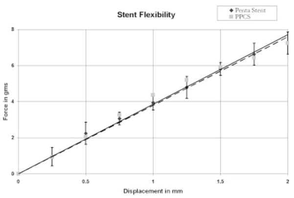
The PPCS was measured for relative longitudinal flexibility by assessing stiffness (the reciprocal of flexibility) using a three-point bend test and determining the slope of the force–displacement curve at room temperature as shown in Figure 7.17 The Penta stent before and after PU application was crimped on a coiled spring mandrel with negligible stiffness and placed between two parallel circular cylinders 18 mm apart as shown in Figure 7 to accommodate the entire length of the stent. Then a force sensor (Dual Range force sensor, Vernier Software and Technology, Beaverton, OR) with a hemispherical tip was pressed on the center of the stent and the force to bend each stent to 2 mm was measured. The displacement of 2 mm was selected by experimental confirmation of the elastic range of the stent under three-point bend test for various displacements. A hemispherical tip was used to establish only a point contact when the force sensor was pressed against the stent. The force sensor had a range of 0–10 N with a resolution of 0.006 N, and accuracy of 0.01 N. Three stents and three runs for each stent before and after application of the PU membrane were obtained to measure the change in stiffness of the stents.
Figure 7.
Three-point bend test setup.
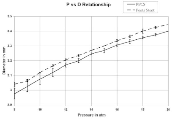
Both the applied pressure and resulting hoop stress have the same units but differ in direction. The hoop stress (σ) is given by the expression σ= PΦ/2t, where P is the pressure, Φ is the tube diameter, and t is coating wall thickness, if a stent is considered as a hollow tube.13 Since in this case the film was applied asymmetrically, the relationship between pressure and hoop stress was not linear. Therefore, it was imperative to experimentally evaluate the change in hoop stress of the stent after the addition of PU membrane. A pressure–diameter relationship of the stent before and after the PU membrane application was determined by measuring the diameter of the stent for a known change in pressure. It was noticed that the expansion of the stent was not symmetrical initially; that is the stent expanded in a dog-bone fashion. Therefore, the pressure–diameter relationship was obtained once the stent was expanded to an initial constant diameter. The diameter of a stent was measured by a Vernier caliper that had a resolution of 10 micrometers while the balloon was inflated through a pressure gauge at known pressure. Three runs for each stent were obtained before and after the application of the PU patch.
Delamination of PU From Stent Struts
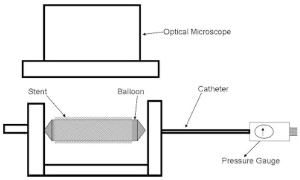
Because of the complex and flexible stents strut scaffold geometry and the fact that the struts themselves could deform when a force was applied, it was not possible to use the standard peel or pull test to measure the force of adhesion. Therefore, a new technique was developed to qualitatively assess the delamination of the membrane from the stent struts as shown in Figure 8. The PPCS was mounted on a balloon and then a standard inflator was used to inflate the balloon and thus expand the stent under the optical microscope. Various regions on the stent were selected and carefully observed for any signs of delamination on stent expansion. These regions were the middle, the proximal, and the distal regions of the coated stent and the outer edges of the membrane on the stent.
Figure 8.
Delamination assessment setup.
Flow Studies
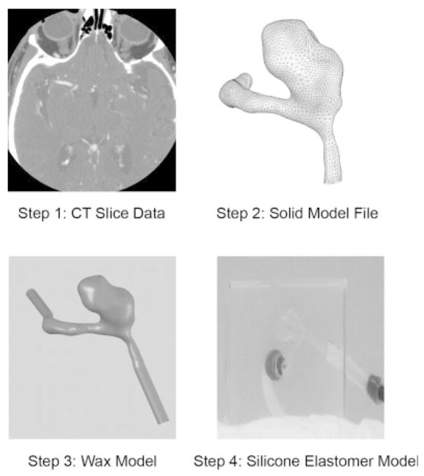
In order to monitor how the inception and growth of cerebral aneurysms might be correlated to hemodynamic flow phenomena in the neurovasculature near the neck of the aneurysm, the potential effectiveness of the PPCS design was evaluated for a patient-specific aneurysm phantom (PSAP) for its flow blocking and modifying properties using time density curves (TDCs).18,19 The construction of the aneurysm phantom was a four step process as shown in Figure 9. In the first step, the PSAP was reconstructed from computed tomographic angiography (CTA) images, in this case, of a 52-year-old female patient’s right ACA aneurysm. The geometric dimensions of the aneurysm and its parent vessel were reconstructed from CTA images composed of 512 × 512 pixels. During the geometry reconstruction process, bone detail was subtracted. Vessels that were quite small such as the anterior communicating artery were not included and the resulting vascular structure was segmented and smoothed for rendering. The second step was creating a 3D volume and converting it into a solid model stereo lithographic (STL) file. In the third step, this STL file was used to make a rapid prototype PSAP model from a low melting temperature wax. The final step included encapsulating this wax model in a silicone elastomer cube and curing the silicone for 24 hours prior to melting the wax to get the final representation of the human vasculature.
Figure 9.
Construction of patient-specific aneurysm phantom.
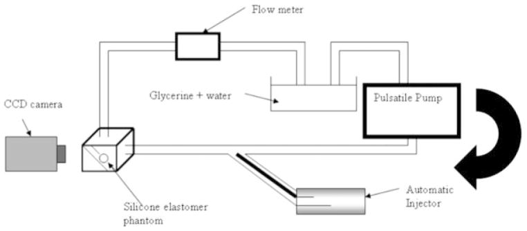
This PSAP was used to study the hemodynamical changes caused in the aneurysm before and after the placement of the PPCS. For this purpose, a pulsatile closed flow loop was established simulating the average Reynolds number between 250 and 30020 as shown in Figure 10. In order to achieve the necessary Reynolds number, viscosity, and density of glycerin/water mixture were adjusted by keeping the diameter and velocity of flow as desired. Since the input geometry was noncircular, the hydraulic diameter was used for a calculation which is 4A/U. “A” stands for cross-sectional area and “U” stands for wetted perimeter; these variables were obtained from the STL file of the PSAP. The (25:75 v/v) glycerin: water mixture was finally used with viscosity 2.45cP and density 1059 kg/m3.21 The average flow velocity was set at 30 cm/sec to simulate the flow in the cerebral arteries that ranges between 25 and 60 cm/sec.22 A charge-coupled device camera was used to image one view of the PSAP carefully selected to avoid overlapping vessels that could interfere with the data collection. An autoinjector (PHD 4400, Harvard Apparatus, Holliston, MA) was used for injection at the rate of 36 ml/min for 2 seconds and the injection site was chosen 20 cm proximal to the aneurysm to avoid perturbation caused by the injection. After the video capture at 30 frames/sec of the bolus injection in the PSAP, different regions of interest (ROI) were selected in the PSAP and TDCs were calculated. Previous computer fluid dynamic (CFD) studies of this phantom23 as verified by angiographic sequences of the untreated case9 indicated that the inflow jet was primarily at the proximal end of the aneurysm orifice. Thus for comparison, the PPCS was carefully placed at the proximal and distal necks of the aneurysm as shown in Figure 11. The patch was intentionally oriented to block the different regions along the neck of the aneurysm to observe the flow modulations when only partial coverage of the aneurysm neck was performed. Similarly the same ROI were sampled on the PSAP with the stent now in place and the corresponding TDCs obtained for comparison with those obtained previously where no stent was in place.
Figure 10.
Flow setup.
Figure 11.
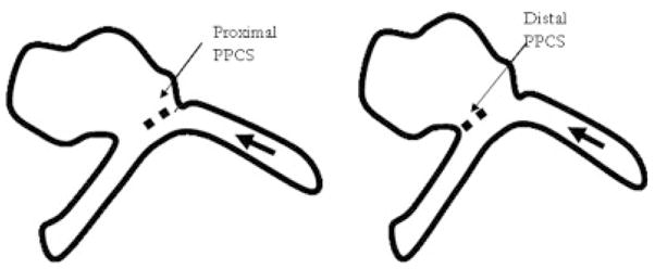
Proximally and distally placed PPCS (flow from right).
A program was developed in-house using LabVIEW software (National Instruments Corp, Austin, TX) to calculate the TDCs. These TDCs were used to evaluate the optical dye flow in the aneurysm before and after PPCS placement. The amount of dye in a given region of a vessel is related to its pixel value in the image. To eliminate the background level variations between different runs and to provide for an intensity value that increases with increasing contrast value in the vessel, the pixel value in the area containing the dye was subtracted from the average background value. For the analysis of the optical dye flow in the aneurysms, a polygonal ROI around the dome was selected. Then, for each frame, the contrast value integral over the ROI area was calculated using the expression shown below:
where dbckg represents the average background pixel value, daneurysm represents the value of an individual pixel in the aneurysm ROI, and D(t) represents the optical dye intensity values integrated over the entire aneurysm area in the image at a particular time t that is, to one frame in the image sequence. Thus D(t) provides a measure of the total amount of contrast media within the aneurysm at any given time.
The amount of contrast entering the aneurysm is directly related to the amount injected through the catheter. To reduce the dependence of D(t) on the absolute concentration of the dye and the lighting conditions during the run, the former was normalized with the total contrast media injected, Dinjected. This total contrast injected was evaluated just proximal to the aneurysm using a line profile. The profile was plotted for each frame to obtain a spatial-temporal distribution of the bolus as shown in Figure 12. This bolus was reproducible since an automatic injector was used. If this distribution is multiplied with average velocity of the bolus, the injection can be normalized by dividing D(t) by Dinjected. The expression for Dinjected is shown below:
where dline is the pixel value along the line profile.
Figure 12.
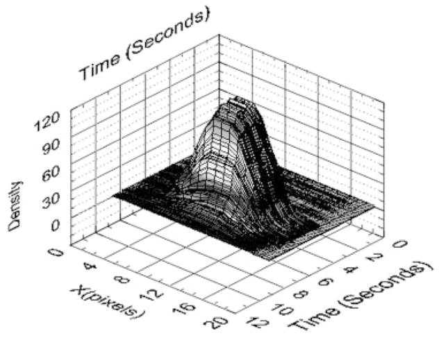
Profile of the bolus injection.
The average velocity in the flow loop was assumed to be constant. The TDC provides information regarding both the input and output flow; hence, some metrics were established to parameterize the curve and thus enable a relative comparison between the stented and the unstented cases. These metrics may eventually be used to study the relationship of these parameters with thrombogenesis in the aneurysm preferably leading to normal flow in the parent artery representing a successful cerebral aneurysm treatment. The rate of input of the TDC was calculated by a finite difference derivative using the expression (di+1 − di)/(ti+1 − ti) where d stands for intensity, t stands for time, and the subscript is the frame number in the video sequence. The washout rate was calculated by fitting an exponential curve to the washout part of the TDC with an R2 value greater than 0.95 using the analytic fit, I = Aexp (−τt ), where I is the contrast intensity, A is the y intercept, τ is the washout rate, and t is time. The residence time was parameterized by calculating the full width half maximum of the TDC. The difference influx is the integral intensity pixel value difference over the aneurysm ROI between the stented and the unstented case normalized to its own input. The difference influx indicates the total amount of dye in the aneurysm with and without the PPCS and measures flow blocking properties of the latter. Since two PSAPs were used for the current study (one for proximal and the other for the distal stent placement) the flow characteristics for both the phantoms were studied with and without PPCS. The percent difference was calculated by the following expression [(USj − Sj )/USj] × 100 where, US stands for the difference influx for the unstented case and S is that for the stented case. These values were used to compare the proximally and distally placed PPCSs.
RESULTS
Stent Fabrication and Radio-Opaque Marking
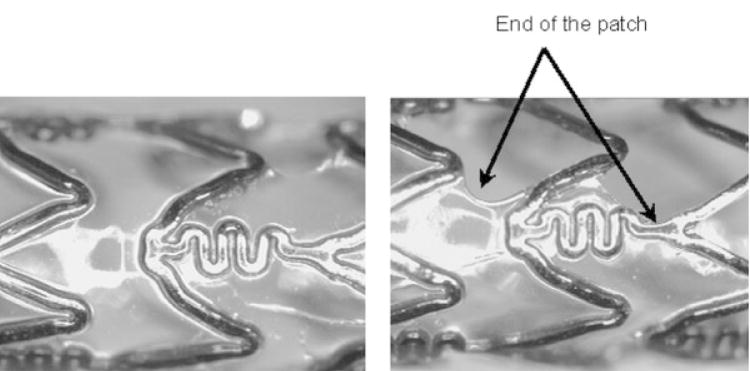
Many PPCSs were created, including one that was dipped partially to get a proximal coating, two magnified portions of which are shown in Figure 13. The magnified images of the middle and edge of the PU membrane on the PPCS are shown in Figure 13(a,b). The coating thickness was a function of number of coats, solvent concentration, dipping rate, and withdrawal rate. In this first demonstration case, precise control on the coating thickness was not attempted. It can be seen in Figure 13(b) that the edge of the coating makes a curvature with the stent struts. This behavior is attributed to the method in which the film was cured on the stent, governed by the surface energy-based spreading interaction of the PU with the stent struts, while the viscous PU was moving and simultaneously curing on the stent. In this case, the stent was partially dipped horizontally and cured vertically toward gravity while inside a convection-based oven at 80°C.
Figure 13.
Magnified view of different regions of the PPCS (a) middle and (b) edge.
To localize the covered part of the stent, four platinum markers for image guidance during the intervention were used. The diameter of the markers (white arrows) as shown in Figure 14 was approximately 100 micrometers and visualized well using a standard X-ray image intensifier (XII), Infinix C-arm system (Toshiba America Medical Systems Corp., Tustin CA), while the stent was within a head phantom in the beam and automatic exposure control was implemented. This configuration was previously used by Ionita et al.24 to verify the accuracy in the rotational or azimuthal localization of an asymmetric stent. Their results indicated that the position of the patch can be identified with a precision of 12 degrees when using a standard XII. These four platinum dot markers indicated the perimeter of the PU film and enhanced the ability to track the location of the patch, thus better enabling the interventional radiologist to successfully localize the stent in the proper orientation in the diseased vessel lumen.
Figure 14.
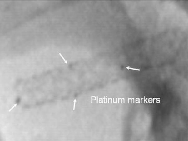
Radiographic image of PPCS platinum marked stent, placed on a head phantom taken with a standard XII system.
Contact Angle Measurements
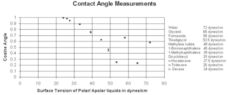
The results of contact angle measurements on the 0% and 100% strained PU membranes on a straining jig are shown in a Zisman plot11 in Figure 15. This figure graphs the cosines of the average measured contact angles (y-axis) against the premeasured liquid/vapor surfaces tensions (x-axis) of highly purified diagnostic liquids applied in sequence from highest to lowest surface tension for the liquids cited earlier. A “best fit” linear extrapolation of the equilibrium plotted data to the cosine contact angle = 1 (contact angle = 0) intercept value, constrained by the physical reality of having this intercept between the values for the lowest surface-tension liquid that did not spread and the highest surface-tension liquid that did spread, defined the CST. In both the cases, the CST of the membrane was between 24 and 30 mN/m. As can be seen from the figure, in both the cases the angles made from liquids water (72 dynes/cm) and formamide (58 dynes/cm) were nonequilibrium values and did not fall in smoothly within the values of all the angles made by the other liquids. This anomaly was due to the fact that both these liquids are very small molecules and hydrogen bond donors and acceptors, able to penetrate and absorb in the polymer matrix. The liquid n-decane with a liquid surface tension of 24 dynes/cm spread similarly in both cases, thus indicating a similar lower limit on CST.
Figure 15.
Zisman Plot of cosine contact angle versus liquid/vapor surface tension for diagnostic liquids on unstrained and 100% strained PU Film.
Stent Flexibility and Pressure–Diameter Relationship Studies
Figure 16 relates to the stiffness of a crimped Penta stent and the PPCS stent, as calculated using a three-point bend measurement test. There was no apparent difference in the stiffness of these stents as the data for each was within one standard deviation of the other. The linear fit indicates that the stiffness of both the 3.0 × 18.0 Penta and the PPCS stents which was derived from the same stent type is 3.8 gms/mm.
Figure 16.
Stiffness of PPCS.
Similarly, in Figure 17 the pressure versus diameter relationship after the stent was already expanded to its nominal diameter of approximately 3 mm is shown. The RMS difference between the two curves is 0.04 mm, which indicated no substantial change in the pressure–diameter relationship of the stent after the application of the PU membrane. The hoop stress, directly proportional to the pressure applied in any cylindrical structure, was not much affected since the coating had a very low modulus of elasticity, was less than 50 micrometers in thickness, and was only partially applied; it did not strongly affect the pressure–diameter relationship of the stent as shown in Figure 17.
Figure 17.
Pressure–diameter relationship of PPCS.
Delamination of PU From Stent Struts
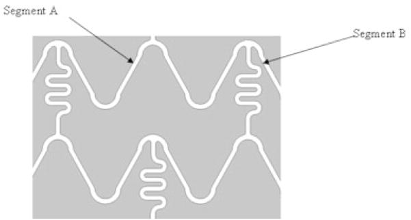
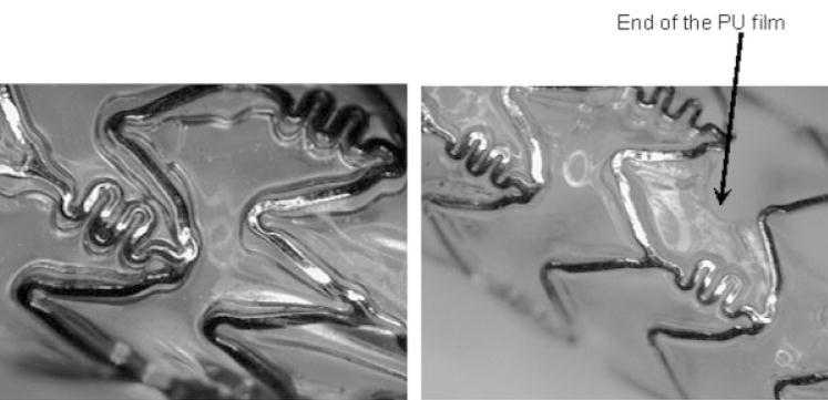
The geometry of the Penta stent is shown in Figures 18 and 19. Segment A undergoes more strain compared with segment B because, as the stent is crimped, segment B is limited by colliding with the “squiggles” shown in Figure 18. The squiggles cannot be further crimped and they play a role in imparting flexibility to the stent for stent deployment inside curved blood vessels. Since segment A is expanded more than segment B, it is important to study the expansion of segment A to observe the worst case scenario and eventually obtain the force of delamination of the PU from the stent strut. Various images are shown of the different regions of the PPCS crimped (Figure 19) and expanded (Figures 20 and 21). In Figure 19, an overhang of the PU film is seen as the stent is crimped to 50% of its original diameter on which it was cured. This patch overhang was measured in four crimped stents and in all the cases the overhang was less than 1.2 mm for the crimped diameter of a 3 × 18.0 PPCS stent. In Figure 20, when the stent was expanded, the expansion was primarily in the circumferential direction rather than in the longitudinal direction and it appeared that the PU film stretching started at the stent strut boundaries where there was an imprint of the struts expansion on the stretched PU film. No delamination was observed on any of the stents expanded between 50% and 100% of its original diameter. However, expanding the stent more than 125% than its original diameter did result in delamination of the film at the edges as shown in Figure 21. The delamination was observed mainly at the edges due to imbalance of forces exerted on the partial coating during PPCS expansion. It should also be noted that, though the PPCS stent was only expanded to 125% of its cured diameter, the local strains within the stent struts could be much higher on some regions of the stent due to asymmetrical expansion of the stent.
Figure 18.
Schematic of the geometry of Penta stent.
Figure 19.
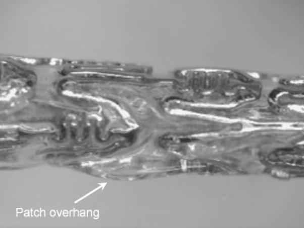
Crimped PPCS.
Figure 20.
Expanded PPCS.
Figure 21.

Delamination of PU film from stent struts.
Flow studies
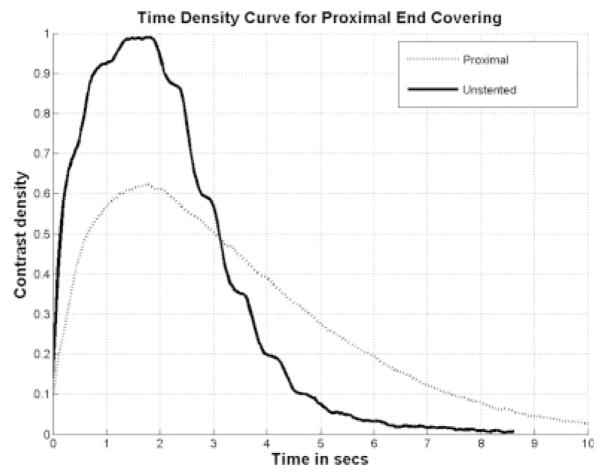
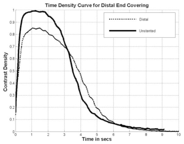
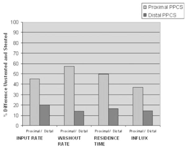
The azimuthal orientation of the PPCS at the aneurysm site is dependent on the torque transfer from the proximal end of the catheter to its distal end while encapsulated in a tortuous path. The angle of rotation at the distal end cannot be estimated accurately and this poses a challenge in exactly aligning the patch with respect to the aneurysm neck. Also, due to the location of the aneurysm inside the vasculature, such as at bifurcations it is not possible to completely cover the aneurysm neck due to the risk involved in jailing other vessels and/or perforators. Therefore, it was preferable to look at the problem from a different perspective and study the changes in the flow because of longitudinally misaligned stents and determine how effective they were in favorable flow modulation in the aneurysm. For this reason, the PPCS was longitudinally oriented to cover only parts of the aneurysm neck to analyze the change in flow dynamics using TDCs. Two different phantoms of intended identical geometry were used as shown in Figures 22 and 23; the TDCs of the unstented cases were actually slightly different because exact reproducibility between two phantoms was not possible because of the difficulty in determining the precise orientation of 3D rapid-prototype wax models in a silicone cast during fabrication of the phantom. Figures 22 and 23 illustrate the TDCs of the entire aneurysm with and without the proximally and distally placed PPCSs. In both the cases, the TDCs were normalized to their respective unstented case. These figures indicate that partial aneurysm coverage does modify the flow, with a proximally placed PPCS in this PSAP modifying flow greater than a distally placed PPCS. Tables 1 and 2 for the proximal and distal placements, respectively, include relative values of the flow and wash-out, and provide further insight in explaining the changes in flow dynamics after PPCS placement. Figure 24 shows the histogram of comparison of all metrics between the proximally and distally placed PPCS. In all the cases the proximally placed PPCS changed the flow more than the distally placed PPCS because it disrupted to a greater extent the proximal inflow jet.
Figure 22.
TDC proximal placed PPCS.
Figure 23.
TDC distal placed PPCS.
TABLE I.
Proximal Placement Results
| Metrics | Unstented (US) | Proximal Stented (PS) | % Difference [(US − PS)/US] × 100 |
|---|---|---|---|
| Input rate (Ŕ), sec−1 | 0.079 | 0.043 | 45.51 |
| Washout rate (τ), sec−1 | −0.742 | −0.318 | 57.14 |
| Residence time (t) | 2.937 sec | 4.406 sec | 50.02 |
| Influx (I) | 1 | 0.629 | 37.04 |
TABLE II.
Distal Placement Results
| Metrics | Unstented (US) | Distal Stented (DS) | % Difference [(US − DS)/US] × 100 |
|---|---|---|---|
| Input rate (Ŕ) | 0.081 | 0.065 | 20.04 |
| Washout rate (τ) | −0.869 | −0.745 | 14.26 |
| Residence time (t) | 3.401 sec | 3.957 sec | 16.34 |
| Influx (I) | 1 | 0.855 | 14.48 |
Figure 24.
Parametric evaluation using TDCs.
DISCUSSION
Currently all the stents available in the medical device market can be broadly categorized as either balloon- or self-expanding stent. The technology described here for balloon-expandable stents, which involves partial coating of the stents, can be extended to self-expanding stents as well.
One current endovascular treatment of choice for neurovascular aneurysms is placing coils possibly in combination with stents for aneurysm embolization. If a stent is used, the stent struts support the coils inside the aneurysm and prevent the coil mass from entering into the parent artery. However, if the aneurysm is wide-necked, defined as an aneurysm with a dome-to-neck ratio less than 2.0 and/or neck length of 4 mm or more,3 coiling becomes difficult and the chance of coil herniation into the parent artery increases drastically. The PPCS described here should be able to replace coils completely because it serves the same purpose of embolizing the aneurysm from the parent artery by creating a stasis environment and reduced wall shear stress. This eventually leads to thrombogenesis and at the same time prevents blockage of small side-branch vessels, perforators, located in and around the aneurysm.
The partial application of the PU on the stent currently requires some manual skill to finely tune the many variables involved in getting the desired geometric result that can be automated in the future. For example, by curing the PU film toward or against gravity on a stent held on a bent glass mandrel, different regions with varied thicknesses as well as different edge formations can be obtained. The asymmetric nature of the PPCS requires radio-opaque marking for a successful intervention. Laser microwelding of the markers enables accurate visualization and aids in placement of the stent along the length of the aneurysm.
A stent with the addition of a PU film modifies both the blood flow and the surface of the stent that comes in contact with the lumen of the blood vessel. The long-term effect of such a permanently implanted structure is not presently known. It is possible that problems of stenosis similar to the restenosis problem exhibited by bare (non-drug-eluting) coronary stents may develop.25 Maintenance of the initial nonbioadhesive CST could enable retention of the passive tissue contact qualities as well as the nonthrombogenic properties of the PPCS. Because the CST is between 24 and 30 dynes/cm, it is likely that the PU film will delay the process of platelet aggregate formation or retention on the parent artery side of the PU film and also resist adhesion to the confining luminal wall.26 It is well known that the surface roughness is also a factor in surface tension. Since there is no significant change in the CST of the strained membrane, one suggested inference is that the microsurface geometry probably does not change much. However, this hypothesis can only be confirmed by measuring surface roughness values of the strained and unstrained membranes. In the current case, the CST was retained in the biocompatibility range, and therefore surface roughness of the PU membrane was not directly measured.
There were only minor changes in the mechanical properties of the PPCS stent compared with the stiffness and hoop stress of the uncoated parent stent. This can be attributed to the low modulus elasticity of the PU membrane and also the partial coating of the film on the stent. There was a slight increase in the hoop stress of the PPCS compared with the Penta stent. The asymmetric patch applied on the surface of the stent changed the response of the PPCS to balloon expansion. This was because, as the stent expanded, the stiffness of the patch along with the plastic deformation of the stent struts offered a resistive force to the force exerted by the balloon. This resistive force varied along the perimeter of the stent due to the PPCS asymmetry. Therefore, it was not possible to determine one absolute value of hoop stress.
The adhesion of the PU to the stent was based on the interaction of the surfaces of the stent struts and the PU and also on the curing time and temperature of the PU on the stent. When the PPCS was cured at room temperature for 12 hours, this resulted in poor adhesion of the film to the stent as compared with curing performed at 80°C. The higher curing temperature was helpful for interfacial water layer dehydration that resulted in better adhesion between the stent struts and the PU membrane.
However, there are various methods of further increasing the wettability of stent struts for better adhesion. One method includes glow discharge plasma treatment of the stent struts before partial dipping of the stent. Baier and Depalma performed early extensive studies on glow discharge treatment of medical devices for improved surface spreading and wetting.27
In ongoing laboratory animal investigations to establish the efficacy of the PPCS, preliminary data indicate that PPCS is capable of embolizing animal model aneurysms. Further developments are necessary before the PPCS can be applied clinically, particularly addressing the effect of substantial but incomplete aneurysmal flow modification. Current research is being carried out to study the flow modulations in different ROI inside an aneurysm, under X-ray image guidance, and further research is in process to correlate simulated flow resulting from CFD calculations with experimental flow modification so that eventually accurate patient-specific treatment plans may be developed.23,28
CONCLUSION
A prototype of a PPCS design to be deployed using image guidance with a standard C-arm X-ray machine was created and its mechanical, surface, and flow-modulating properties were evaluated. It was found that the modification of currently available commercial stents with a partial PU film does not change appreciably the flexibility and the hoop stress of the stent. Therefore, current technology of endovascular catheters can be used to place these medical devices at the aneurysm site using minimally invasive treatment. The surface properties of the polycarbonate-based PU film, inspected using contact angle measurements included results showing that the PU film has a CST in the biocompatibility range where biological interaction between the body and the biomaterial stays minimum. The flow studies in a silicone elastomer PSAP revealed that the PPCS was capable of modulating the flow entering the aneurysm and can be used to controllably block selected regions along the aneurysm neck. Four specific metrics (input rate, washout rate, residence time, influx) can form the basis of quantifying the flow dynamics and establishing a relation of these variables with the thrombus formation expected for aneurysms in animal and clinical studies. The PPCS appears to be a promising device for cerebral aneurysm treatment; however, it must be further evaluated in vivo with animal studies before being used in clinical treatments.
Acknowledgments
The authors acknowledge the support from Toshiba Medical Systems Corporation for an equipment grant and Guidant Corporation for stents.
Contract grant sponsor: NIH; contract grant numbers: R01 EB002873, R01 NS43024, R01 EB02916
References
- 1.Barath K, Cassot F, Rufenacht DA, Fasel JH. Anatomically shaped internal carotid artery aneurysm in vitro model for flow analysis to evaluate stent effect. AJNR. 2004;25:1750–1759. [PMC free article] [PubMed] [Google Scholar]
- 2.Lanzino G, Wakhloo AK, Fessler RD, Hartney ML, Guterman LR, Hopkins LN. Efficacy and current limitations of intravascular stents for intracranial internal carotid, vertebral, and basilar artery aneurysms. J Neurosurg. 1999;91:538–546. doi: 10.3171/jns.1999.91.4.0538. [DOI] [PubMed] [Google Scholar]
- 3.Wanke I, Doerfler A, Schoch B, Stolke D, Forsting M. Treatment of wide-necked intracranial aneurysms with a self-expanding stent system: Initial clinical experience. AJNR. 2003;24:1192–1199. [PMC free article] [PubMed] [Google Scholar]
- 4.Katsaridis V, Papagiannaki C, Violaris C. Placement of a Neuroform2 stent into the parent vessel by navigating it along the inner wall of the aneurysm sac: A technical case report. Neuroradiology. 2007;49:57–59. doi: 10.1007/s00234-006-0155-3. [DOI] [PubMed] [Google Scholar]
- 5.Doerfler A, Wanke I, Egelhof T, Stolke D, Forsting M. Double-stent method: Therapeutic alternative for small wide-necked aneurysms. Technical note J Neurosurg. 2004;100:150–154. doi: 10.3171/jns.2004.100.1.0150. [DOI] [PubMed] [Google Scholar]
- 6.Krings T, Hans FJ, Moller-Hartmann W, Brunn A, Thiex R, Schmitz-Rode T, Verken P, Scherer K, Dreeskamp H, Stein KP, Gilsbach J, Thron A. Treatment of experimentally induced aneurysms with stents. Neurosurgery. 2005;56:1347–1359. doi: 10.1227/01.neu.0000159887.03290.d1. [DOI] [PubMed] [Google Scholar]
- 7.Rudin S, Wang Z, Kyprianou I, Hoffmann KR, Wu Y, Meng H, Guterman LR, Nemes B, Bednarek DR, Dmochowski J, Hopkins LN. Measurement of flow modification in phantom aneurysm model: Comparison of coils and a longitudinally and axially asymmetric stent—initial findings. Radiology. 2004;231:272–276. doi: 10.1148/radiol.2311021741. [DOI] [PubMed] [Google Scholar]
- 8.Sherman JR, Rangwala HS, Ionita CN, Dohatcu AC, Bednarek DR, Hoffmann KR, Rudin S. Investigation of new flow modifying endovascular image-guided interventional (EIGI) techniques in patient specific aneurysm phantoms (PSAPs) using optical imaging. Proceedings from Medical Imaging 2008: Visualization, Image-Guided Procedures, and Modeling; San Diego, CA: SPIE; 2008. p. 6918. [DOI] [PMC free article] [PubMed] [Google Scholar]
- 9.Kim M, Ionita CN, Tranquebar RV, Hoffmann KR, Taulbee DB, Meng H, Rudin S. Evaluation of an Asymmetric Stent Patch Design for a Patient Specific Intracranial Aneurysm using Computational Fluid Dynamic (CFD) Calculations in the Computed Tomography (CT) Derived Lumen. Proceedings from Medical Imaging 2006: Physiology, Function, and Structure from Medical Images; San Diego, CA: SPIE; 2006. p. 6143. [DOI] [PMC free article] [PubMed] [Google Scholar]
- 10.Dohatcu AC, Ionita CN, Bednarek DR, Hoffmann KR, Rudin S. Endovascular image-guided treatment of in-vivo model aneurysms with asymmetric vascular stents (AVS): Evaluation with Time-Density Curve angiographic analysis and histology. Proceedings from Medical Imaging 2008: Physiology, Function, and Structure from Medical Images; San Diego, CA: SPIE; 2008. p. 6916. [DOI] [PMC free article] [PubMed] [Google Scholar]
- 11.Ionita CN, Yadava GK, Keleshis CM, Hoffmann KR, Bednarek DR, Rudin S. In-vivo endovascular image guided interventions (EIGI) using the high-sensitivity micro-angiographic fluoroscope (HS-MAF). Proceedings from Medical Imaging 2008: Visualization, Image-Guided Procedures, and Modeling; San Diego, CA: SPIE; 2008. p. 6918. [DOI] [PMC free article] [PubMed] [Google Scholar]
- 12.Ionita CN, Paciorek A, Hoffmann KR, Bednarek DR, Yamamoto J, Kolega J, Levy EI, Hopkins LN, Rudin S, Mocco J. Asymmetric Vascular Stent (AVS): Feasibility study of a new stent with a low porosity patch for treatment of canine aneurysm model. Stroke. 39:2105–2113. doi: 10.1161/STROKEAHA.107.503862. [DOI] [PMC free article] [PubMed] [Google Scholar]
- 13.Trigwell S, De S, Sharma R, Mazumder MK, Mehta JL. Structural evaluation of radially expandable cardiovascular stents encased in a polyurethane film. J Biomed Mater Res B. 2006;76:241–250. doi: 10.1002/jbm.b.30359. [DOI] [PubMed] [Google Scholar]
- 14.Szycher M. Szycher’s Handbook of Polyurethanes. CRC Press; Boca Raton, FL: 1999. [Google Scholar]
- 15.CardioTech International Inc. Fact Sheet, ChronoFlex AR. Biodurable Medical Grade Polyurethane Cardiotech International Inc; Wilmington, MA: 2004. Available at: http://www.cardiotech-inc.com/chronoflex_ar_factsheet.html. [Google Scholar]
- 16.Zisman WA. Relation of the equilibrium contact angle to liquid and solid constitution. In: Gould RF, editor. Contact Angle, Wettability and Adhesion. Washington, DC; ACS: 1964. pp. 1–50. [Google Scholar]
- 17.Ormiston JA, Dixon SR, Webster MW, Ruygrok PN, Stewart JT, Minchington I, West T. Stent longitudinal flexibility: A comparison of 13 stent designs before and after balloon expansion. Catheter Cardiovasc Interv. 2000;50:120–124. doi: 10.1002/(sici)1522-726x(200005)50:1<120::aid-ccd26>3.0.co;2-t. [DOI] [PubMed] [Google Scholar]
- 18.Wang Z, Ionita C, Rudin S, RHoffmann K, Paxton AB, Bednarek DR, Amini AA, Manduca A. Angiographic analysis of blood flow modification in cerebral aneurysm models with a new asymmetric stent. Proceeding of the SPIE 2004; Bellingham, WA: SPIE; 2004. pp. 307–318. [DOI] [PMC free article] [PubMed] [Google Scholar]
- 19.Hoffmann K, Doi K, Fencil L. Determination of instantaneous and average blood flow rates from digital angiograms of vessel phantoms using distance-density curves. Invest Radiol. 1991;26:207–212. doi: 10.1097/00004424-199103000-00001. [DOI] [PubMed] [Google Scholar]
- 20.Stuhne GR, Steinman DA. Finite-element modeling of the hemodynamics of stented aneurysms. J Biomech Eng. 2004;126:382–387. doi: 10.1115/1.1762900. [DOI] [PubMed] [Google Scholar]
- 21.OPTIM Glycerine. Available at: www.dow.com/glycerine.
- 22.Aaslid R, Markwalder TM, Nornes H. Noninvasive transcranial Doppler ultrasound recording of flow velocity in basal cerebral arteries. J Neurosurg. 1982;57:769–774. doi: 10.3171/jns.1982.57.6.0769. [DOI] [PubMed] [Google Scholar]
- 23.Kim M, Rangwala H, Ionita C, Hoffmann KR, Taulbee DB, Meng H, Rudin S. In: Cleary K, Miga M, editors. Evaluation of the effect of partial asymmetric stent coverage on neurovascular aneurysm hemodynamics using computer fluid dynamics (CFD) calculations; Proceedings of the SPIE; Bellingham, WA: SPIE; 2007. p. 65092I. [Google Scholar]
- 24.Ionita CN, Rudin S, Hoffmann KR, Bednarek DR, Galloway Robert L, Jr, Cleary Kevin R. Microangiographic image-guided localization of a new asymmetric stent for treatment of cerebral aneurysms. Medical Imaging: Visualization, Image-Guided Procedures, and Display. Proceedings of the SPIE; Bellingham, WA: SPIE; 2005. pp. 354–365. [DOI] [PMC free article] [PubMed] [Google Scholar]
- 25.Szycher M, Armini A, Bajgar C, Lucas A. Drug-eluting stents to prevent coronary restenosis. 2002 Available at: http://www.implantsciences.com/pdf/IMXpaperv2-rev2.pdf.
- 26.De S, Sharma R, Trigwell S, Laska B, Ali N, Mazumder MK, Mehta JL. Plasma treatment of polyurethane coating for improving endothelial cell growth and adhesion. J Biomater Sci. 2005;16:973–989. doi: 10.1163/1568562054414612. [DOI] [PubMed] [Google Scholar]
- 27.Baier RE, Depalma VA. Cornell Aeronautical Laboratory Report No. 176. Vol. 14221. Buffalo, NY: 1970. Electrodeless glow discharge cleaning and activation of high-energy substrates to insure their freedom from organic contamination and their receptivity for adhesives and coatings; p. 17. [Google Scholar]
- 28.Rudin S, Bednarek DR, Hoffmann KR. Endovascular Image Guided Interventions (EIGI). Invited Vision 20/20 paper. Med Phys. 2008;35:301–309. doi: 10.1118/1.2821702. [DOI] [PMC free article] [PubMed] [Google Scholar]


