Abstract
Transduction-channel gating by hair cells apparently requires a gating spring, an elastic element that transmits force to the channels. To determine whether the gating spring is the tip link, a filament interconnecting two stereocilia along the axis of mechanical sensitivity, we examined the tip link's structure at high resolution by using rapid-freeze, deep-etch electron microscopy. We found that the tip link is a right-handed, coiled double filament that usually forks into two branches before contacting a taller stereocilium; at the other end, several short filaments extend to the tip link from the shorter stereocilium. The structure of the tip link suggests that it is either a helical polymer or a braided pair of filamentous macromolecules and is thus likely to be relatively stiff and inextensible. Such behavior is incompatible with the measured elasticity of the gating spring, suggesting that the gating spring instead lies in series with the helical segment of the tip link.
By opening or closing transduction channels, deflection of the mechanically sensitive hair bundle initiates mechanoelectrical transduction in hair cells (1). Bundle deflection stretches elastic elements, the gating springs, which transmit force to the hundred or so transduction channels per cell (2). The best candidate for the gating spring is the tip link, an extracellular filament that joins a stereocilium to its tallest neighbor, parallel to the bundle's axis of mechanical sensitivity (3). Tip links should be stressed during excitatory stimuli, be slackened during inhibitory ones, and be unaffected by stimuli perpendicular to the sensitivity axis. When tip links were eliminated by brief exposure to the Ca2+ chelator 1,2-bis(O-aminophenoxy)ethane-N,N,N′,N′-tetraacetic acid (BAPTA), mechanoelectrical transduction disappeared and the bundle moved >100 nm, as if the gating springs had been abruptly disengaged (4). In addition, tip links regenerated within 24 h after BAPTA treatment, with mechanoelectrical transduction returning over the same time span (5). Because BAPTA rapidly severs tip links and has few effects on other stereociliary linkages, tip links either are the gating springs or are connected in series with them (4).
The molecular identity of the tip link is unknown. By transmission electron microscopy (TEM), tip links appear as amorphous filaments of ≈5 nm diameter and 150–300 nm length (3, 6). The lower end of a tip link contacts an intracellular osmiophilic structure, the tip density, whereas the other end contacts another osmiophilic structure, the insertional plaque (6). Its sensitivity to proteases (7, 8) and ability to be labeled by polycationic compounds (9) suggests that the tip link is a glycosylated protein. If the tip link is the gating spring, biophysical estimates of its stiffness (≈1 mN⋅m-1) indicate that it should withstand forces of >100 pN and stretch more than twice its resting length (2, 10). To further explore the function and molecular identity of the tip link, we have chosen to characterize its structural properties and its sensitivity to chemical perturbations. To produce higher-resolution images of the tip-link fine structure, we used the rapid-freeze, deep-etch technique (11, 12), with improved metal replication and imaging procedures. We find that although it is likely to be an essential element for transduction, the tip link's structure seems incompatible with previous suggestions that it makes up the entire elastic gating spring.
Materials and Methods
Tissue Preparation for Electron Microscopy.
Auditory (guinea pig cochlea) and vestibular (guinea pig utriculus and bullfrog sacculus) sensory tissues from adult animals were dissected and processed for thin-section and freeze-fracture electron microscopy as described (13). For rapid-freeze, deep-etch (freeze-etch) microscopy, each tissue was fixed with 2–4% glutaraldehyde, rinsed in distilled water, and mounted in a drop of water on a cushioned rapid-freezing support (11, 12). Samples were rapid-frozen by contact with the surface of a sapphire block cooled to −186°C with liquid N2 by using a Life Cell CF-100 freezing apparatus. Water covering the specimen was lowered before freezing to position hair bundles within a superficial layer of ≈10–15 μm, the only region that becomes optimally frozen (11, 12). Rapidly frozen samples were transferred to a Balzers freeze-fracture apparatus, freeze-fractured at −120°C, and etched for 8–15 min at −100°C.
Rotary Shadowing.
Using electron-beam metal-evaporation guns (Cressington Scientific, Cranberry, PA), surfaces of freeze-etched samples were rotary-shadowed by evaporation of atomized platinum/carbon and were further reinforced with a carbon layer. The platinum/carbon evaporation gun was positioned at 12–30° for rotary shadow and the carbon gun at 90°. The amount of platinum/carbon and carbon deposited was adjusted by using a quartz-crystal thin-film monitor. Conventional freeze-fracture replicas are made of ≈2 nm platinum/carbon and 10–20 nm carbon films (14). We made most of our freeze-etching replicas with about 10–50% less platinum and 100–300% more carbon. Minimization of evaporated platinum prevented formation of large granular deposits on the freeze-etched surfaces (see Results). Replicas were cleaned in dilute sodium hypochlorite and picked up on copper grids.
Electron Microscopy Imaging.
Replicas were viewed with a Zeiss 902 electron microscope equipped with an energy-loss spectrometer and a goniometer stage. High-contrast images were produced by zero-loss imaging, i.e., filtering out the inelastically scattered electrons and using only the elastically scattered electrons. Electron-micrograph negatives were digitized by using a Leaf 45 scanner (Leaf Systems, Southborough, MA). Image processing was performed by using the National Institutes of Health image program.
Chemical Disruption of Tip Links.
The apical surface of the basilar papilla was exposed from excised temporal bones of newborn chickens (5). Papillae were incubated at room temperature in a standard saline solution (155 mM NaCl, 6 mM KCl, 3 mM d-glucose, 5 mM N-2-hydroxyethylpiperazine-N′-2-ethanesulfonic acid at pH 7.4), with or without added Ca2+. When measured by atomic absorption, our nominally Ca2+-free saline contained 1.4 μM Ca2+. For measurement of pH sensitivity, the standard saline solution was buffered with 5 mM each of glycylglycine, acetic acid, 2-[N-morpholino]ethanesulfonic acid,N-2-hydroxyethylpiperazine-N′-2-ethanesulfonic acid, and 3-[cyclohexylamino]-1-propanesulfonic acid. After treatment of basilar papillae, the pH of the solution was measured to confirm that the pH remained unchanged. After exposure to agents for 10 min, papillae were washed with saline solution, treated with 50 μg/ml subtilisin (Sigma protease type XXIV) to remove the tectorial membrane, fixed, and processed for scanning electron microscopy (SEM) as described (5). Proteases and chloride salts of divalent and trivalent cations were obtained from Sigma; glycosidases were purchased from Boehringer Mannheim. In some cases, papillae were cultured after BAPTA treatment as described (5); tip-link regeneration was qualitatively similar to that seen previously.
Results
Resolution of Freeze-Fracture and Freeze-Etching Replicas.
Deposition of evaporated metal, required for imaging, greatly influences the appearance and resolution of freeze-fracture replicas (14). Several factors must be considered when using rotary-shadowed metal replicas of freeze-etched samples to characterize molecular structures by appearance. To produce a metal replica, high-energy atomic particles are used to bombard the tissue surface. During impact, the metal particles transfer some of their kinetic energy to delicate biological macromolecules; bombarding metal atoms embed into the surface, modifying surface structures and heating the specimen. Heating can rapidly degrade the low-mass, free-standing structure of the tip link. Continuous bombardment also produces nucleation and growth of small microcrystals (metal grains). In our freeze-etch replicas, initial bursts of high-energy platinum atoms evaporated from the electron beam gun are likely to lodge deep within freeze-dried tip-link structures. A low amount of bombarded metal atoms produces, at the expense of contrast and reproducibility, a finer positively stained image of smaller structure details. By contrast, when larger amounts of platinum are deposited, structures are covered with a frosting of microcrystallized platinum, which highlights other surface details (12). Metal grain sizes for a thin coat of platinum have diameters of 1–2 nm (14).
The appearance of tip links depended greatly on metal-evaporation parameters. Rotary evaporation (shadowing) produces optimal information of surface topography of objects, as long as they are symmetrical and properly positioned in relation to the evaporation angle. Despite controlling the thickness of the metal coating, the thickness of shadowed replicas varied significantly from place to place because of patterns and angles formed by the highly convoluted surfaces of hair bundles. Because they could be shadowed by stereocilia, tip links were often poorly exposed to the platinum rotary evaporation.
Replicas also can be eroded during tissue digestion and replica cleaning; in addition, resolution can be degraded by recrystallization of metal atoms during exposure of the replica to the imaging electron beam. Another significant limitation in freeze-etch imaging of hair bundles is that the resulting images are two-dimensional projections of three-dimensional structures; distance is often impossible to measure. Our situation differs from freeze-etch imaging on a mica surface, where the biological structure is entirely laid out on the two-dimensional surface (12).
Because of the relative scarcity of tip links and the technical difficulties mentioned above, our rate of successful imaging was very low. We made more than 120 replicas from about 40 guinea pigs and 40 bullfrogs. We photographed 58 tip-link images that we judged to be free of obvious specimen-preparation artifacts; about two-thirds of these were from the bullfrog sacculus and the remainder were from guinea pig cochlea and utriculus.
The Helical Structure of the Tip Link.
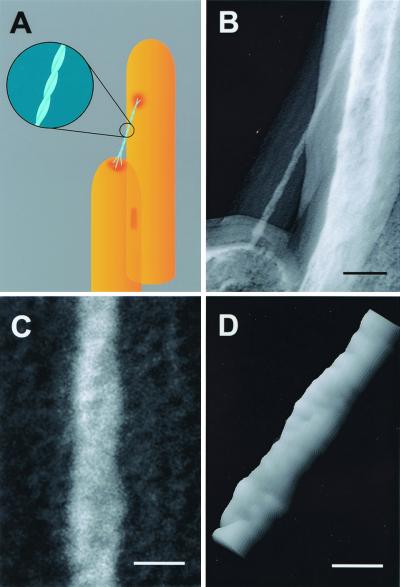
The best images of tip links were obtained from replicas produced with the smallest amounts of evaporated platinum and the highest amounts of carbon; our interpretation of key features is shown in Fig. 1A. Fig. 1B shows our best image of the extended portion of a tip link. This image shows a symmetrical shadow and very small grain sizes. Zero-loss imaging allowed considerable contrast enhancement despite the low amount of electron-dense platinum. The very small platinum grains appear to be embedded in the structure, giving the appearance of a positive contrast rather than a frosting coat. Because of the increased contrast generated with the zero-loss imaging, the images of the carbon coat are also enhanced and appear as very visible halos around the contoured surfaces, partially blurring the imaging of the platinum. A particularly heavy carbon coat was used in this replica, which protected the tip link's platinum coat during tissue digestion and prevented radiation damage and platinum recrystallization during imaging.
Figure 1.
Helical structure of the tip link. (A) Proposed model for tip-link structure. Two helically intertwined protofilaments (Inset) make up the tip link, attaching at two points to the taller stereocilium and contacting three filaments emanating from the shorter stereocilium. (B) Freeze-etch image of tip link from guinea pig cochlea. Note the thick carbon coat forming a halo around the tip link and the stereocilia surface. (C) Higher magnification view of the tip link in B; we suggest that the reader view this figure from a shallow angle perspective (from bottom to top) to better view the helical configuration of the tip link. We confirmed right-handedness by imaging stereo pairs with the concave side of the replica up. (D) Surface plot of the pixel intensities of the digitized image of the tip link shown in B created with National Institutes of Health image. The pseudo-three-dimensional image helped visualize the helical configuration and the possible periodic substructure of the protofilaments. (Scale bars: B = 50 nm; C and D = 10 nm.)
A magnified image (Fig. 1C) shows clearly that the extended domain of the tip link is formed by a coiled double filament. The two protofilaments formed a right-handed helix with a 60-nm period. Although we noted a possible periodic substructure within each protofilament, more apparent in a surface plot of the magnified image (Fig. 1D), the periodicity was close to the limit of resolution using this technique.
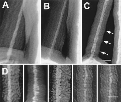
Because irradiation damage and platinum recrystallization damaged and distorted tip links during imaging, we chose to emphasize images least damaged by the visualization technique. Consequently, tip links varied in appearance and diameter. Fig. 2 A–C shows the same tip link viewed at different tilt angles, illustrating the changes in the thickness of the platinum image and the carbon halo from different angles, as well as demonstrating deterioration of the platinum image during continued irradiation. Fig. 2D shows a gallery of tip-link extended segments. Although the platinum grains are not as small as those in Fig. 1, these tip links also showed a 30-nm periodicity of thinner and thicker regions, consistent with the helical structure with 60-nm pitch seen clearly in Fig. 1. This periodicity was also impressed into the carbon halo. We made measurements of the diameter of the projected helical images of the tip links at different portions of the thinner and the thicker regions. The measured average diameter was 8.3 ± 0.2 nm (n = 10) at the thinner regions and 10.3 ± 0.3 nm (n = 23) at the thicker regions.
Figure 2.
Variability in appearance of tip-link extended structure. (A–C) Images of the tip link of Fig. 1B acquired with different tilt angles showing different apparent thickness of the tip link and its carbon coat. Despite degradation of the platinum image of the tip link, the enveloping carbon coat still shows the 30-nm periodic widening (arrows) and narrowing consistent with the projected view of a helical structure. (D) Images of the extended structure of different tip links from guinea pig cochlea (first two panels from left to right) and from bullfrog sacculus (three panels to the right). (Scale bars = 15 nm.)
Multiple Attachments of the Tip Link.
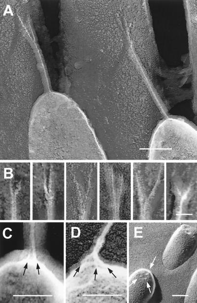
Attachment of the tip link to the stereocilia was different at each end. At the upper end, the tip link consistently split apart about 10–50 nm from the taller stereocilium, so that two branches attached to this stereocilium (Fig. 3). Of the 58 tip links we examined, 27 were clearly bifurcated, 10 were appropriately oriented but bifurcation was not apparent, and the remainder were inappropriately oriented for us to distinguish bifurcation. Although the branches appear to have a diameter about half that of the tip link (Fig. 3B), their fragility during irradiation made this estimation of very limited quantitative value. In some cases, we saw images where one of the branches appeared to be recoiled or retracted (Fig. 3B, first panel). Although the appearance of two branches at the point of insertion with the taller stereocilium has been previously observed by SEM (6) and tip-link bifurcation can also be occasionally observed in thin sections (Fig. 4D), these images show that branching is a consistent feature of tip-link structure.
Figure 3.
Upper and lower attachments of the tip link. (A and B) Freeze-etch images of tip-link upper insertions in guinea pig cochlea (A) and (left to right) two from guinea pig cochlea, two from bullfrog sacculus, and two from guinea pig utriculus (B). Each example shows pronounced branching. (C and D) Freeze-etch images of the tip-link lower insertion in stereocilia from bullfrog sacculus (C) and guinea pig utriculus (D); multiple strands (arrows) arise from the stereociliary tip. (E) Freeze-fracture image of stereociliary tips from bullfrog sacculus; indentations at tips are indicated by arrows. (Scale bars: A = 100 nm, B = 25 nm; C–E = 100 nm.)
Figure 4.
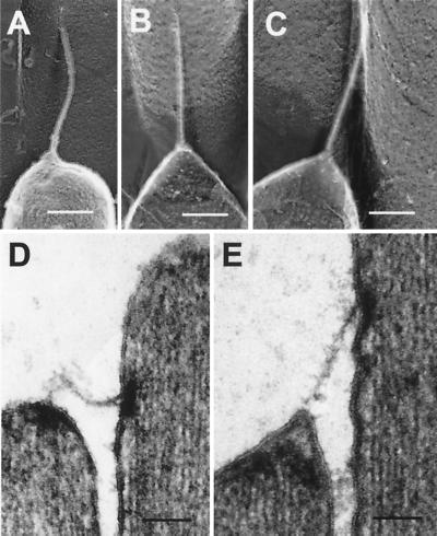
Response of the tip link to compressive and tensile forces. (A) Freeze-etch images of a smoothly buckled bullfrog tip link. (B and C) Freeze-etch images of a bullfrog tip link apparently under tension; note that lower membrane is cone-shaped, suggesting that tenting is present. (D) Thin-section TEM image of a tip link in a relaxed state. (E) Thin-section TEM image of a tip link in a tensed state. The membrane appears to pull away from the tip density. (Scale bars = 100 nm.)
The structure of the tip link's insertion into the membrane of the shorter stereocilium was more difficult to resolve. Because the tip link inserts at a near-perpendicular angle, a side view of this insertion point is partially blurred by the carbon film that coats the membrane. In rare occasions where we could discern features of this insertion point, the tip link appeared to branch into or contact two or three strands, each ≈25–40 nm in length, which we call anchor filaments (Fig. 3 C and D). Coincidentally, fortuitous freeze-fracture images that show the tops of the stereocilia also revealed three indentations, spaced ≈20–30 nm apart, which apparently corresponded to the insertions of the three branches into the membrane (Fig. 3E). Large intermembrane particles have been previously localized near this region in cochlear hair cells (15).
Bending and Stretching of Tip Links.
In 13 of the 58 tip links examined, we observed tip links that appeared to be under compression (Fig. 4A). In all cases, the tip links appeared smoothly buckled and without sharp bends, indicating high flexural rigidity. Similar behavior was observed in thin-section TEM images (Fig. 4D). These samples were subjected to chemical fixation; buckling observed therefore might arise from increased flexural rigidity afforded by fixation. Nevertheless, because fixation should immobilize adjacent stereocilia and prevent them from sliding along each other and stressing the tip links, tip-link buckling more likely reflects the structure in an unfixed state.
We frequently saw images of tip links that appeared tensed, apparently pulling the membrane of the shorter stereocilium away from the underlying cytoskeleton (Fig. 4 B and C). This phenomenon, known as tenting, also has been observed by thin-section TEM (refs. 6, 16, and 17; Fig. 4E).
Sensitivity of the Tip Link to Various Chemical Disruption.
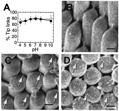
To gain further insight into their composition and properties, we examined chicken basilar papilla tip links for susceptibility to cations, sugars, proteases, and other agents. Many had no significant effects on tip links (Table 1). One protease previously reported to sever tip links, elastase (7), was ineffective unless we pretreated papillae with N-glycosidase F; chondroitinase ABC accentuated this effect (Table 1). Tip links remained largely intact after treatment with saline solutions buffered from pH 4 to 10 (Fig. 5A). By contrast, tip links were eliminated after exposure to 1 mM La3+ or Tb3+ (Table 1). After tip links were broken with BAPTA, field-emission SEM revealed small protuberances, tip-link remnants (18), exactly where tip links had been attached to the shorter stereocilium (Fig. 5C). These remnants may correspond to the anchor filaments at the lower end of the tip link. Protuberances of similar dimensions were observed in greater numbers on stereociliary tips during intermediate steps of tip-link regeneration that followed BAPTA treatment (Fig. 5D).
Table 1.
Effect of disruptive agents on tip links
| Agent | Score |
|---|---|
| 1 mM LaCl3 | − (4) |
| 5 mM LaCl3 | − (2) |
| 1 mM TbCl3 | +/− (3) |
| 5 mM TbCl3 | − (1) |
| 20 mM BaCl2 | +/− (3) |
| 10 mM sodium periodate | +/− (8) |
| 25 mM mannose-6-phosphate | +/− (4) |
| 10 mM acetylneuraminic acid | +/− (2) |
| 1 mg/ml elastase, 200 units/ml N-glycosidase F | +/− (3) |
| 1 mg/ml elastase, 10 units/ml chondroitinase ABC, 200 units/ml N-glycosidase F | − (5) |
| 1 mg/ml chymotrypsin, 200 units/ml N-glycosidase F | +/− (3) |
| 1 mg/ml chymotrypsin, 10 units/ml chondroitinase ABC, 200 units/ml N-glycosidase F | − (5) |
Basilar papillae were treated for 10 min with the indicated reagents. For combinations of glycosidases (N-glycosidase F and chondroitinase) and proteases, papillae were first treated with glycosidases for 30 min, followed by a wash and a 10-min protease treatment. Scores: (+), 50–100% number of tip links as control; (+/−), 15–50% of control; (−), 0–15% of control; number of papillae examined in parentheses. The following were scored (+) with one or two papillae each: 1 mM BaCl2, 1 mM CoCl2, 5 mM MnCl2, 10 mM galactose, 10 mM mannose, 10 mM lactose, 10 mM fucose, 10 mM mannose-1-phosphate, 25 mM fucose-1-phosphate, 10 mM N-acetyl-d-galactosamine, 10 mM N-acetyl-d-glucosamine, 1 mM methyl-α-d-mannopyranoside, 5 mM heparin, 1 mg/ml chondroitin sulfate, 100 μg/ml fucoidan, 200 units/ml N-glycosidase F, and 10 units/ml chondroitinase ABC. The following were scored (+) with one or two papillae each at 0.5 mg/ml and 1 mg/ml: trypsin, chymotrypsin, papain, bromelain, ficin, protease K, S. aureus V8 protease, and elastase.
Figure 5.
Response of tip links to chemical treatment. (A) Chicken basilar papillae were exposed to solutions of varying pH and either 4 mM (●) or 1.4 μM (○) CaCl2. For each point, tip links from 14–16 hair bundles from 3–4 papillae were counted from SEM images; each point corresponds to ≈1,000 tip-link positions. Means ± standard error are plotted. Bundles were chosen from all regions of the papilla. (B–D) Field-emission SEM images of chicken basilar-papilla hair bundles before and after BAPTA treatment. (B) Control. (C) Immediately after BAPTA treatment; remnants are seen where tip links formerly anchored (arrows). (D) 2 h after BAPTA treatment, during tip-link regeneration. Protuberances on the surface of each stereociliary tip are indicated by arrows. [Scale bars: B = 200 nm (applies to C and D).]
Discussion
Because tips links are so scarce and difficult to assay, conventional methods for identification and characterization of biological macromolecules cannot be readily applied to them. Structural determination with electron microscopy does, however, allow description of properties of the tip link that may assist in identification of its molecular constituents. Although the freeze-etch technique generates high-resolution images of surface topography of biological specimens, image quality depends critically on parameters of replica preparation and imaging that are difficult to control. Although these limitations inevitably increased variability between specimens, many structural features of the tip link were reproducibly observed. The thick carbon-evaporation coating in our replicas (e.g., Fig. 1B) protected tip links and may have accounted for our success in observing tip links compared with other freeze-etch studies of hair cells (19, 20).
Tip-Link Structure.
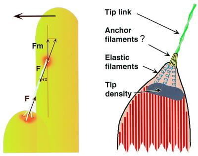
The tip link consists of a pair of protofilaments, arranged helically for most of their length; they usually bifurcate into single filaments, which skim along the surface of the membrane for tens of nanometers (Fig. 3; refs. 4, 6, and 21). At the shorter stereocilium, our best images suggest that the protofilaments contact three short anchor filaments, which probably pass through the membrane. Because only 10–20 pN is required to extract a transmembrane protein from a bilayer (22, 23), unanchored transmembrane tip-link receptors, even three or more, cannot survive forces generated during large bundle deflections. Intracellular filaments connecting the osmiophilic tip density to the membrane (17)—which may be intracellular portions of the anchor filaments—therefore likely connect tip links to the cytoskeleton (Fig. 6).
Figure 6.
Models for tip-link structure. (Left) Model indicating buckling forces during tip-link compression. At the buckling force F, the force pushing the upper insertion point parallel to the membrane is Fm = F cos(α), where α is the angle formed by the tip link and the stereocilium (≈30°). (Right) Model for tip-link structure demonstrating responses to tip-link extension; note tenting of membrane and extended putative elastic filaments located between the membrane and the osmiophilic tip density.
Macromolecular Composition of the Tip Link.
Sensitivity to proteases and glycosidases reinforces the suggestion that a glycoprotein forms an essential part of the tip link. Interestingly, chicken hair bundles appear significantly less sensitive to the protease elastase than other bundles (7, 8). Noncovalent interactions at either end (or both ends) are sensitive not only to Ca2+ but also to lanthanide ions. Lanthanide ions may compete with Ca2+ for binding to sites that maintain tip-link integrity when Ca2+ occupies them; correspondingly, millimolar concentrations of La3+ irreversibly destroy transduction (24). By contrast, noncovalent interactions in the tip link were surprisingly insensitive to pH extremes (Fig. 5). At least one Ca2+-binding site that maintains tip-link integrity may be near the shorter stereocilium; tip remnants observed after BAPTA treatment (Fig. 5D) may be residual anchor filaments, suggesting that tip links disengage from those structures. Whether tip links also disengage from the taller stereocilium during BAPTA treatment is not known.
The relatively large diameter of the tip link makes it highly unlikely that it is composed of polysaccharide or polynucleotide chains. This portion of the tip link therefore must be formed by polypeptides, either as a polymer of many subunits or as a dimer of two extended chains. Double-stranded, helical polymers like actin can be strong; for example, the force required to rupture an actin filament is ≈100 pN (25). If the tip link is a helical polymer that remains intact during large bundle displacements, the large number of monomer-monomer contacts required for strength would likely render the filament very stiff; for example, an actin filament with the length of a tip link would have a stiffness of ≈300 mN⋅m-1 (26), much larger than that of the gating spring.
Polymer models for the tip link face several challenges, however. Tip-link length appears relatively uniform within a given bundle or organ and across species (3–6, 21); a template therefore would be required to permit precise control of filament length. In addition, the bifurcation of the tip link into two strands creates a problem. A double-stranded helical structure like actin is stable because monomers can interact both along the protofilament axis and between protofilaments (27). If the protofilaments of a polymeric helical structure could be disentwined, they would rapidly disintegrate. Depending on how the branches of the tip link connect with the membrane, however, they may have to withstand forces up to half as great as the helical section of the tip link.
The tip link also might be constructed of two extended polypeptide filaments, helically coiling around each other. Familiar elongated and coiled protein structures, such as a single α-helix, a coiled-coil, or a triple helix, form structures too narrow to be tip links. The tip link could be similar to other elongated proteins known to be elastic, such as titin (≈0.7 mN⋅m-1 per 150 nm; ref. 28) and tenascin (≈2 mN⋅m-1 per 150 nm; ref. 29); titin and tenascin, however, do not helically dimerize. Although other elongated extracellular proteins do dimerize, they do usually do so in an antiparallel orientation (30, 31); by contrast, the asymmetry of the tip-link structure strongly suggests a parallel orientation of the protofilaments. Interestingly, Ig tandem domains dimerize in parallel, both in Fc and Fab interactions (32).
Protofilaments making up the tip link must contact each other on many surfaces, stabilizing the helical structure and likely stiffening it. This conclusion is supported by images where the tip link undergoes smooth bending without unraveling (Fig. 4). Although tip links can appear stretched under some conditions (8, 33), studies reporting tip-link stretching used thick metal coating, which might have obscured stretching of one of the tip link's attachments.
We propose that the tip link is significantly stiffer than the gating spring. If a helical polymer makes up the extended portion, it must be nearly inextensible. If a double filament constitutes the extended portion, it is still likely to be much stiffer than paired 150-nm titin or tenascin molecules, which already would be stiffer than the gating spring.
Implications for Models of Transduction.
Active transduction channels apparently can be found near either end of a tip link (34). If the tip link directly gates channels at both ends, the link's asymmetric structure implies that the channel-tip link connection differs at the two ends. Alternatively, transduction channels may be indirectly coupled or gated by structures other than tip links (35).
If tip links are rigid, they could convey compressive forces to transduction channels until buckling. If the tip link lacks a hinge or other flexible region (a correct assumption if images such as those in Fig. 4 reflect properties of the unfixed link), the force required to buckle the tip link (F) is given by F = π2 YI/L2, where YI is the flexural rigidity, and L is the tip link length (Fig. 6). If the flexural rigidity of the tip link resembles that of actin, ≈10-25 M⋅m2 (36), the buckling force would be ≈40 pN; an inhibitory displacement of ≈250 nm in bullfrog sacculus could provide this force. By contrast, if its flexural rigidity was similar to that of the muscle-protein titin, 10-28 M⋅m2 (28), only ≈40 fN would be required to buckle the tip link. Measured under the same conditions, however, titin molecules are narrower than the tip link (37). The tip-link buckling force is therefore likely to be considerably higher than the lower value. Although saturating channel-closure kinetics, decreased bundle stiffness for negative displacements, and adaptation rates for negative steps all imply that gating springs can slacken (2), rigid tip links may transmit compressive forces once the gating springs have slackened.
The proposed inextensibility of the tip link suggests that another elastic element within the hair bundle is the true gating spring, and that the tip link instead connects to it in series to direct force to the channel (2, 4); alternatively, elasticity could be shared among several components, perhaps including the tip link. Although rigorous measurement of tip-link length and separation of the membrane from the tip density during mechanical stimuli would address this issue directly, these experiments are extremely difficult with thin-section TEM and, because of the projection problem mentioned above, are especially difficult with freeze-etch microscopy. The tip link appears too rigidly attached to the cytoskeleton at the taller stereocilium for an elastic element to be present there. By contrast, the membrane of the shorter stereocilium often is tented away from the underlying cytoskeleton and tip density, suggesting that an elastic element might be located there. Membrane bilayers are probably far too compliant to serve as the gating spring (38). Instead, we suggest that intracellular filaments connecting the tip density to the membrane (17) are better candidates to form the gating spring (Fig. 6).
Acknowledgments
We thank Drs. Jorgen Fex and David Lim for help in early stages of this study and Fabio Mammano for help with buckling-force calculations. P.G.G. was supported by the National Institutes of Health and the Pew Scholars in the Biomedical Sciences Program.
Abbreviations
- BAPTA
1,2-bis(O-aminophenoxy)ethane-N,N,N′,N′-tetraacetic acid
- SEM
scanning electron microscopy
- TEM
transmission electron microscopy
Footnotes
This paper was submitted directly (Track II) to the PNAS office.
References
- 1.Hudspeth A J. Nature (London) 1989;341:397–404. doi: 10.1038/341397a0. [DOI] [PubMed] [Google Scholar]
- 2.Hudspeth A J. Soc Gen Physiol Ser. 1992;47:357–370. [PubMed] [Google Scholar]
- 3.Pickles J O, Comis S D, Osborne M P. Hearing Res. 1984;15:103–112. doi: 10.1016/0378-5955(84)90041-8. [DOI] [PubMed] [Google Scholar]
- 4.Assad J A, Shepherd G M G, Corey D P. Neuron. 1991;7:985–994. doi: 10.1016/0896-6273(91)90343-x. [DOI] [PubMed] [Google Scholar]
- 5.Zhao Y, Yamoah E N, Gillespie P G. Proc Natl Acad Sci USA. 1996;93:15469–15474. doi: 10.1073/pnas.93.26.15469. [DOI] [PMC free article] [PubMed] [Google Scholar]
- 6.Furness D N, Hackney C M. Hearing Res. 1985;18:177–188. doi: 10.1016/0378-5955(85)90010-3. [DOI] [PubMed] [Google Scholar]
- 7.Osborne M P, Comis S D. Acta Otolaryngol (Stockh) 1990;110:37–45. doi: 10.3109/00016489009122513. [DOI] [PubMed] [Google Scholar]
- 8.Takumida M, Harada Y, Kanemia Y. ORL J Otorhinolaryngol Relat Spec. 1993;55:77–83. doi: 10.1159/000276384. [DOI] [PubMed] [Google Scholar]
- 9.Neugebauer D-C, Thurm U. Cell Tissue Res. 1987;249:199–207. [Google Scholar]
- 10.Shepherd G M G, Corey D P. J Neurosci. 1994;14:6217–6229. doi: 10.1523/JNEUROSCI.14-10-06217.1994. [DOI] [PMC free article] [PubMed] [Google Scholar]
- 11.Heuser J E, Kirschner M W. J Cell Biol. 1980;86:212–234. doi: 10.1083/jcb.86.1.212. [DOI] [PMC free article] [PubMed] [Google Scholar]
- 12.Heuser J E. J Mol Biol. 1983;169:155–195. doi: 10.1016/s0022-2836(83)80179-x. [DOI] [PubMed] [Google Scholar]
- 13.Kachar B, Liang F, Lins U, Ding M, Wu X R, Stoffler D, Aebi U, Sun T T. J Mol Biol. 1999;285:595–608. doi: 10.1006/jmbi.1998.2304. [DOI] [PubMed] [Google Scholar]
- 14.Maunsbach A B, Afzelius B A. Biomedical Electron Microscopy. London: Academic; 1999. [Google Scholar]
- 15.Forge A, Davies S, Zajic G. J Neurocytol. 1988;17:325–334. doi: 10.1007/BF01187855. [DOI] [PubMed] [Google Scholar]
- 16.Assad J A, Hacohen N, Corey D P. Proc Natl Acad Sci USA. 1989;86:2918–2922. doi: 10.1073/pnas.86.8.2918. [DOI] [PMC free article] [PubMed] [Google Scholar]
- 17.Pickles J O, Rouse G W, von Perger M. Scanning Microscopy. 1991;5:1115–1129. [PubMed] [Google Scholar]
- 18.Meyer J, Furness D N, Zenner H P, Hackney C M, Gummer A W. J Neurosci. 1998;18:6748–6756. doi: 10.1523/JNEUROSCI.18-17-06748.1998. [DOI] [PMC free article] [PubMed] [Google Scholar]
- 19.Hirokawa N, Tilney L G. J Cell Biol. 1982;95:249–261. doi: 10.1083/jcb.95.1.249. [DOI] [PMC free article] [PubMed] [Google Scholar]
- 20.Forge A, Davies S, Zajic G. J Neurocytol. 1991;20:471–484. doi: 10.1007/BF01252275. [DOI] [PubMed] [Google Scholar]
- 21.Jacobs R A, Hudspeth A J. Cold Spring Harbor Symp Quant Biol. 1990;55:547–561. doi: 10.1101/sqb.1990.055.01.053. [DOI] [PubMed] [Google Scholar]
- 22.Bell G I. Science. 1978;200:618–627. doi: 10.1126/science.347575. [DOI] [PubMed] [Google Scholar]
- 23.Evans E, Berk D, Leung A. Biophys J. 1991;59:838–848. doi: 10.1016/S0006-3495(91)82296-2. [DOI] [PMC free article] [PubMed] [Google Scholar]
- 24.Baumann M, Roth A. J Comp Physiol A. 1986;158:681–688. doi: 10.1007/BF00603825. [DOI] [PubMed] [Google Scholar]
- 25.Kishino A, Yanagida T. Nature (London) 1988;334:74–76. doi: 10.1038/334074a0. [DOI] [PubMed] [Google Scholar]
- 26.Higuchi H, Yanagida T, Goldman Y E. Biophys J. 1995;69:1000–1010. doi: 10.1016/S0006-3495(95)79975-1. [DOI] [PMC free article] [PubMed] [Google Scholar]
- 27.Holmes K C, Popp D, Gebhard W, Kabsch W. Nature (London) 1990;347:44–49. doi: 10.1038/347044a0. [DOI] [PubMed] [Google Scholar]
- 28.Higuchi H, Nakauchi Y, Maruyama K, Fujime S. Biophys J. 1993;65:1906–1915. doi: 10.1016/S0006-3495(93)81261-X. [DOI] [PMC free article] [PubMed] [Google Scholar]
- 29.Oberhauser A F, Marszalek P E, Erickson H P, Fernandez J M. Nature (London) 1998;393:181–185. doi: 10.1038/30270. [DOI] [PubMed] [Google Scholar]
- 30.Shapiro L, Fannon A M, Kwong P D, Thompson A, Lehmann M S, Grubel G, Legrand J F, Als-Nielsen J, Colman D R, Hendrickson W A. Nature (London) 1995;374:327–337. doi: 10.1038/374327a0. [DOI] [PubMed] [Google Scholar]
- 31.Jensen P H, Soroka V, Thomsen N K, Ralets I, Berezin V, Bock E, Poulsen F M. Nat Struct Biol. 1999;6:486–493. doi: 10.1038/8292. [DOI] [PubMed] [Google Scholar]
- 32.Silverton E W, Navia M A, Davies D R. Proc Natl Acad Sci USA. 1977;74:5140–5144. doi: 10.1073/pnas.74.11.5140. [DOI] [PMC free article] [PubMed] [Google Scholar]
- 33.Comis S D, Osborne M P, Jeffries D J. Acta Otolaryngol. 1990;109:49–56. doi: 10.3109/00016489009107414. [DOI] [PubMed] [Google Scholar]
- 34.Denk W, Holt J R, Shepherd G M, Corey D P. Neuron. 1995;15:1311–1321. doi: 10.1016/0896-6273(95)90010-1. [DOI] [PubMed] [Google Scholar]
- 35.Hackney C M, Furness D N. Am J Physiol. 1995;268:C1–C13. doi: 10.1152/ajpcell.1995.268.1.C1. [DOI] [PubMed] [Google Scholar]
- 36.Gittes F, Mickey B, Nettleton J, Howard J. J Cell Biol. 1993;120:923–934. doi: 10.1083/jcb.120.4.923. [DOI] [PMC free article] [PubMed] [Google Scholar]
- 37.Funatsu T, Kono E, Higuchi H, Kimura S, Ishiwata S, Yoshioka T, Maruyama K, Tsukita S. J Cell Biol. 1993;120:711–724. doi: 10.1083/jcb.120.3.711. [DOI] [PMC free article] [PubMed] [Google Scholar]
- 38.Sleep J, Wilson D, Simmons R, Gratzer W. Biophys J. 1999;77:3085–3095. doi: 10.1016/S0006-3495(99)77139-0. [DOI] [PMC free article] [PubMed] [Google Scholar]


