

Abstract
We physically cross-linked a thermoreversible poly(vinyl alcohol) (PVA) hydrogel (TG) within a crystalline colloidal array (CCA) to form an enabling photonic crystal material. The TG consists of a physically cross-linked network formed in a process reminiscent of the well-known freeze-thaw physically cross-linking process, but which avoids solvent freezing which invariably disorders the CCA. These TGCCA can be inexpensively fabricated in any large volume and shape by avoiding the previous covalently polymerized CCA constraints that required thin sheet geometries to enable penetration of the UV light used to photopolymerize the system. This TG hydrogel enables rigidificaton of CCA crystals and subsequent chemical functionalization. In addition, an additional interpenetrating hydrogel can be polymerized within the TGPCCA. The TG can then be dissolved away by simply increasing the temperature. The TGCCA photonic crystal diffraction is highly efficient and similar to previously demonstrated PCCA with covalent cross-links. These TGCCA are stable for weeks or longer at room temperature and can be utilized as photonic crystal materials. They also can be irreversibly covalently cross-linked by using gluteraldehyde. These gluteraldehyde cross-linked TGCCA can be made into chemically responsive sensor photonic crystals by functionalizing the PVA hydroxyl groups with chemical recognition agents. We demonstrate low and high pH sensing by functionalizing with carboxylates and phenol derivatives, respectively.
Introduction
There is intense interest in the fabrication of photonic crystal materials which can be used to control the propagation of light.1-3 We previously developed responsive photonic crystal materials by covalently polymerizing acrylamide-like hydrogels within self-assembled crystalline colloidal arrays4 (CCA). The CCA consists of an array of ∼100 nm or larger spherical particles of high surface charge which electrostatically repel one another such that the system self-assembles into a generally face-centered cubic (fcc) array crystal which Bragg diffracts light in the UV, visible, or IR spectral region depending on the fabricated lattice constant.5 By covalently polymerizing a hydrogel within the CCA (PCCA) we form a soft material whose diffraction directly depends upon the volume of the system.6 A major application of these PCCA is for chemical sensors.7,8 For this application chemical recognition agents are attached to the PCCA to cause changes in hydrogel volume in proportion to the concentration of the analyte. The resulting diffraction wavelength shifts conveniently and directly report on the volume changes.
A major limitation of the previous PCCA is that few hydrogel monomers are consistent with CCA self-assembly since the electrostatic interactions are screened by even low concentrations of ionic species. In order to surmount this limitation we have developed a method to form a physically cross-linked hydrogel around the CCA.
We use thermoreversible gelation (TG) to embed a CCA within a poly(vinyl alcohol) (PVA) hydrogel to form a thermoreversibly gelled crystalline colloidal array (TGCCA). The TG hydrogel consists of a physically cross-linked network which can be later dissolved by increasing the temperature.
This reversible gelation stabilizes the CCA ordering such that further harsh chemical functionalization can occur, whereupon the physically cross-linked hydrogel can be dissolved away. Further, interpenetrating networks can be covalently polymerized within the TGCCA which would be normally incompatible with CCA self-assembly. After the TGPCCA is dissolved away a novel PCCA remains.
The TGPCCA polymerization process allows us for the first time to fabricate photonic crystals of any size and geometry because there is no requirement for a thin film geometry to allow for penetration of UV light to obtain homogeneous polymerization. TGCCA have similar diffraction properties to our previously reported polymerized CCA (PCCA) materials.6 The simplicity of the synthetic process broadens the range of PCCA-based materials which can now be synthesized.
Our original motivation for developing thermoreversible hydrogels was derived from a need to develop nitrogen-free and low polymer content PCCA that are stable against oxidation and hydrolysis for use as ammonia sensors.9 PVA is inexpensive, safe, biocompatible, and already used for in vivo applications.10 PVA hydrogels show promise for use in the development of artificial tissues, contact lenses, implantable devices, and as vehicles for drug delivery.11
PVA hydrogels have been made through both covalently and physically cross-linking PVA polymer solutions. PVA hydrogels have been covalently cross-linked with dialdehydes, γ-radiation, or the polymerization of PVA macromers.12 Physically cross-linked PVA hydrogels have typically been made through the well-known freeze-thaw process.13 In a deviation from the freeze-thaw process, Hyon et al. described the preparation of transparent PVA hydrogels from mixed solutions of DMSO and water without freezing the solvents.14 In their procedure, PVA was dissolved and poured into a mold at 90 °C and the temperature lowered to -20 °C. Optically clear hydrogels formed at the appropriate compositions from the cooled liquid.15 Hydrogels made in nonfrozen solvent conditions have been called psychrotrophic gels (from psychria meaning chill);13 however, this terminology has not been generally adopted. These hydrogels form due to a homogeneous nanocrystallite formation throughout the PVA solution.
The psychrotrophic hydrogels developed by Hyon et al. differ substantially from cryogels made through the better-known freeze-thaw process. A cryogel forms as the solvent freezes and the PVA is concentrated into the nonfrozen regions of the solution. The concentration of PVA in the nonfrozen regions increases, and the PVA crystallizes. The structure of the PVA cryogel is determined by the crystallization of the liquid. These cryogels typically appear turbid because the three-dimensional (3-D) crystalline polymer network contains large channels formed by the frozen liquid.14,15
In contrast, psychrotropic gels are formed through spinodal decomposition.16,17 The solution is supersaturated due to the low temperature and unfavorable solvent conditions (cononsolvency). The solution becomes unstable against infinitesimal fluctuations in composition. The nanocrystallites of PVA form as the solution spontaneously separates into two phases.16
The TGCCA synthesized here are optically similar to our previously developed photopolymerized PCCA.6-8 However, the hydrogel can be melted by increasing the temperature. We also demonstrate that the TGCCA can be made thermally stable by utilizing simple dialdehyde cross-linking. The cross-linked TGCCA can be made responsive to chemical stimuli by functionalizing the hydrogel. This expands the chemical and physical properties of PCCA photonic crystal materials.
Experimental Section
PCCA Preparation
A typical preparation of a TGCCA involves mixing a solution of poly(vinyl alcohol) (Polysciences, 98 mol % hydrolyzed, MW ∼78 000) 5% (w/w) in dimethyl sulfoxide (DMSO, Fisher) with the CCA solution. The CCA solution contains monodisperse cross-linked polystyrene colloidal particles (110 nm, 10% w/w in water).17 After mixing the PVA solution and CCA solution, ion-exchange resin (Bio-Rad AG 501-X8 (D) resin) is added and the mixture agitated until strong diffraction is visually evident (2 min). The ion-exchange resin is removed through centrifugation, the TGCCA precursor solution is poured or injected into a mold, and the temperature lowered. After 2 h at -20 °C, the solvent remains unfrozen, but the TGCCA has gelled and can be removed from the cell.
The rectangular sample shown in Figure 1 was made by placing 0.5 mL of the TGCCA precursor solution between two square glass plates separated by a 100 μm spacer. When the plates were forced together, the precursor solution spread evenly throughout the cell and the excess solution was forced out the cell edges.
Figure 1.
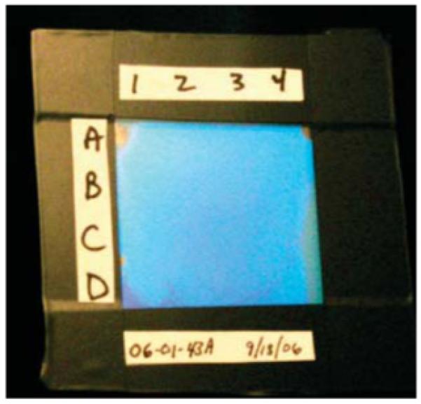
3 cm × 3 cm TGCCA fabricated between glass plates by using a 100 μm thick polyester spacer to separate the TGCCA from the adhesive used to seal the edges of the glass plates. The cell was divided into 16 9 mm square regions (A1-D4) that were analyzed via UV-vis transmission spectroscopy by using a 5 mm diameter aperture.
The glass and quartz plates were cleaned by soaking in 1 M NaOH (Fisher), with subsequent rinsing with water, acetone (EM Science), and methanol (EM Science). After drying in an oven at 140 °C, SigmaCote (Sigma) was pipetted onto the warm surface and allowed to evaporate. SigmaCote is a solution of a chlorinated organopolysiloxane in heptane which reacts with surface silanol groups on glass to produce a neutral, hydrophobic, microscopically thin film.18 The glassware was placed back in the oven at 140 °C for 20 min and, after cooling, rinsed with methanol.
Diffraction and Transmission Measurements
The backscattered diffraction from a TGCCA was monitored using a fiber-optic diode spectrometer with a tungsten halogen light source (Ocean Optics) and a reflectance probe. The diffraction spectra in Figure 2b were measured by contacting the fiber-optic probe against the glass wall.
Figure 2.
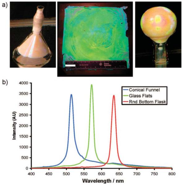
(a) Conical funnel, glass plates, and a round-bottom flask containing fabricated TGCCA. The planar 16 cm × 16 cm sample shown has a thickness of 500 μm. Included for reference is a 15 cm ruler and a 25 mm scale bar. The TGCCA in the round-bottom flask and funnel have volumes of 50 mL. (b)Reflectance spectra from each TGCCA.
The relationship between the diffracted wavelength of light (λ0) and the lattice spacing closely follows Bragg’s law:
| (1) |
We monitor the back-diffracted light normal to the PCCA surface (θ) = 90°) to characterize the lattice spacing and the volume of the hydrogel. The diffracted wavelength in air, λ0, depends on the diffracting plane spacing, d, and the refractive index of the system, n.
UV-vis transmission spectra were measured by a Varian Cary 5000 UV-vis spectrophotometer. These samples were measured while contained within the glass or quartz cell in which they were prepared. Samples were measured within 1 day of preparation. Locations on the samples were labeled in a grid pattern. Each region of the grid was measured independently utilizing a 5 mm round aperture. The spectrometer was run in dual beam mode. The reference beam passed through a cell prepared in an identical manner to that utilized for the TGCCA, but filled with 18 MΩ water.
Transmission Electron Microscopy of the PVA Layer
A 6% solution of 180 nm colloidal particles was mixed with a 5% solution of 78 000 MW PVA in DMSO. The solution was mixed by turning it end-over-end for 2 h. A drop of this solution was diluted to 3 mL in a 50% DMSO and water solution and dried on a 75 mesh 3.0 mm o.d. copper transmission electron microscopy (TEM) grid (Ted Pella). The sample was placed in a vacuum oven at 40 °C for 2 h under reduced pressure. The micrograph was taken with a Jeol JEM-1400 using an accelerating voltage of 80 kV and a magnification of 180 000.
Testing Thermal Reversibility
A TGCCA was fabricated between a set of 6 cm × 6 cm glass plates. A polyester film spacer (∼100 μm thick, Grafix, Inc.) was cut so as to contain a 36 mm × 36 mm × 100 μm PCCA. This spacer was placed between the plates to provide a uniform TGCCA thickness and to separate the TGCCA precursor solution from the adhesive used to seal the edge of the cell (Instant Krazy Glue, Elmer). The TGCCA precursor was placed in the cell, and the cell closed. Excess precursor solution was drawn out of the spacer region by utilizing a Kim-Wipe. After the spacer region dried, adhesive was added to the edge of the cell and capillary action drew the adhesive into the spacer region. After the adhesive had set, the cell was placed at -20 °C for 2 h to gel the sample. The gel was then placed in an 85 °C oven for 30 min to melt the TGCCA. Melting was confirmed by movement of an air bubble trapped in the cell.
Formation of Covalent Cross-Links
A 40 mL solution of 50% DMSO and water was added to a 125 mL Nalgene straight-side wide-mouth jar. Volumes of 0.6 mL of glutaraldehyde solution (Sigma, grade II, 25%) and 0.4 mL of concentrated sulfuric acid (J.T. Baker) were then added. A 3 cm × 3 cm (250 μm thick) TGCCA sample was cut into 16 pieces with a razor blade and placed in the Nalgene jar. To quench the reaction, TGCCA pieces were removed and immersed in gently stirred pure water. The bath water was replaced after 5 min.
Conjugation of Carboxylic Acid
A covalently cross-linked TGCCA was exchanged from pure water to pure DMSO through a gradient with steps at 25%, 50%, 75%, and 100% DMSO. After 2 h in each solution, the TGCCA was transferred into the more concentrated DMSO solution. The 100% DMSO solution (200 mL) was replaced three times, with 2 h equilibration times. The TGCCA was placed into a 40 mL solution of DMSO containing 0.22 g of succinic anhydride (Sigma). The reaction was allowed to proceed for 2 h at room temperature prior to rinsing with DMSO. The TGCCA was then solvent-exchanged through the DMSO/water gradient to pure water. Diffraction spectra were taken with a reflectance probe as the carboxylated TGCCA was titrated with 20 mM HCl (Fisher) solution in the presence of 150 mM NaCl. The 20 mM HCl solution was added dropwise, and the pH was monitored. After each acid addition, the TGCCA was allowed to equilibrate, a spectrum was taken, and the pH was recorded.
Conjugation of 3-Aminophenol
An amount of 0.5 g of 3-aminophenol (3-AMP, 4.6 mmol, Sigma) was dissolved in 10 mL of DMSO (J.T. Baker) and then diluted to 50 mL with 50 mM phosphate buffer solution (PBS, Pierce Biotechnology). The TGCCA was incubated for 4 h in the 3-AMP solution. An amount of 0.5 g of 1-ethyl-3-(3-dimethylaminopropyl) carbodiimide hydrochloride (EDC, 0.52 mmol, Pierce Biotechnology) was dissolved in the solution containing the TGCCA, and the reaction was allowed to proceed for 2 h. The 3-AMP functionalized PCCA was rinsed repeatedly with a 150 mM NaCl (J.T. Baker) solution and titrated as above except utilizing 20 mM NaOH (Fisher).
Results and Discussion
TGCCA formed through the thermoreversible gelation process can be made much thicker than photopolymerized PCCA because the thickness attainable through UV photopolymerization is limited by the optical density of the PCCA precursor solution. Particles which strongly scatter or absorb UV light prevent initiation of the free-radical polymerization deep within the hydrogel. Furthermore, the thermoreversible approach allows the use of photochemically unstable molecules to be incorporated within the TGCCA during synthesis.
Another benefit of the TGCCA synthetic process is that it does not require the specialized quartz containers required by the UV photopolymerization process. The thick TGCCA shown in Figure 2 were made in standard laboratory glassware; TGCCA can also be fabricated inside plastic and metal molds.
Each TGCCA has a volume of 50 mL, about 100-fold larger than typically prepared PCCA (0.5 mL). The visually apparent sample iridescence results from the back-diffraction of light from the fcc 111 planes of the embedded CCA. Figure 2b shows the characteristic back-diffraction spectra of the TGCCA. The diffracted wavelength of each TGCCA differ because they were prepared at different colloid particle concentrations. Figure 3 shows the reflectance spectra of a series of TGCCA made in plastic cuvettes at various colloid concentrations. Obviously, the diffracted wavelengths can span the entire visible spectrum.
Figure 3.
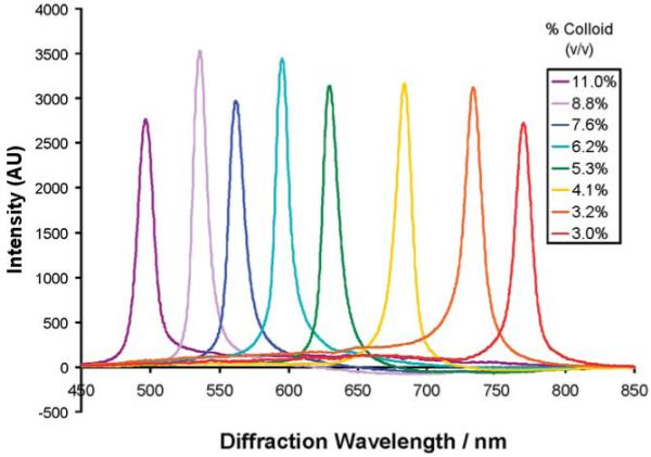
TGCCA made with 5% 78 kDa PVA and 110 nm diameter particles diffract different wavelengths of light depending on the concentration. TGCCA can be made to diffract anywhere in the visible spectrum.
DMSO Enables the Embedding of Colloidal Particles
The role of each component within the TGCCA precursor solution was examined by thermally cycling compositions which lacked one or more of the components necessary for fabricating TGCCA. The following Table 1 lists the composition of the samples shown in Figure 4:
Table 1. Samples in Figure 4 Made with Different Compositions.
| a (%) | b (%) | c (%) | d (%) | e (%) | f (%) | |
|---|---|---|---|---|---|---|
| PVA | 5.00 | 5.00 | 5.00 | 5.00 | 0.00 | 0.00 |
| colloid | 0.00 | 0.00 | 7.50 | 7.50 | 7.50 | 7.50 |
| water | 95.00 | 42.50 | 87.50 | 43.75 | 92.50 | 46.25 |
| DMSO | 0.00 | 42.50 | 0.00 | 43.75 | 0.00 | 46.25 |
Figure 4.
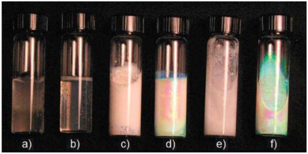
All samples were maintained at -20 °C for 3 h and photographed after warming to room temperature, except for sample a which was cycled six times between -20 °C and room temperature. (a) 5% PVA in pure water. (b) 5% PVA in a 50% DMSO/water. (c) 5% PVA and 7.5% colloidal particles in pure water. (d) 5% PVA and 7.5% colloidal particles in a 50% DMSO/water. (e) 7.5% colloidal particles in pure water. (f) 7.5% colloidal particles in 50% DMSO/water.
Figure 4 shows the impact of cooling these samples to -20 °C for 3 h and then returning them to room temperature. The photograph was taken with each sample lying on its side slightly tilted. After thermal cycling, sample a remained liquid, whereas sample b gelled. Sample a, which consists of PVA dissolved in pure water, was subjected to five additional thermal cycles. At -20 °C, sample a appeared frozen; when inverted, the sample did not flow. Furthermore, the surface of the sample was corrugated and air bubbles were dispersed throughout the sample. Upon returning to room temperature, sample a returned to the liquid state. Over the course of six additional thermal cycles, sample a became more viscous until it gelled and became infinitely viscous after the sixth cycle. Sample b, which is PVA dissolved in DMSO and water, gelled after a single cooling cycle.
Samples c and d are identical to samples a and b, respectively, except that they additionally contain colloidal particles. Before being cooled to -20 °C, both samples ordered into a CCA and strongly diffracted light. Sample c, made without DMSO, exhibited no diffraction after being cooled to -20 °C. Like sample a, sample c appeared frozen at -20 °C with ice protruding from the surface. Unlike sample a, sample c gelled after a single thermal cycle. Sample d, made with DMSO, water, colloidal particles, and PVA, gelled to form a strongly diffracting TGCCA after a single cooling cycle.
Samples e and f are colloidal suspensions containing no PVA. Although both CCA initially diffracted light, sample e froze at -20 °C and the diffraction disappeared. After returning to room temperature, sample e melted and the colloidal particles appeared to be aggregated, with much precipitate. At -20 °C, sample f remained an unfrozen CCA. Upon returning to room temperature, sample f continued to diffract similarly to that prior to the temperature decrease.
Samples a and b demonstrate two different mechanisms of PVA gelation. Without DMSO, the solution freezes and the hydrogel that forms is called a cryogel or a freeze-thaw gel. The mechanism of formation for this type of hydrogel has been studied extensively.13-17 Samples e and f demonstrate the affect of solvent freezing on CCA ordering. Freezing causes the particles to aggregate extensively and become disordered presumably due to exclusion of the particles to the interfaces between frozen crystallites. DMSO depresses the freezing point of the solution below -20 °C, and CCA remains ordered (sample f). Sample c, made without DMSO, froze during the thermal cycling. The presence of the PVA did not prevent the CCA from disordering upon solvent freezing. Sample d forms an ordered TGCCA because the DMSO depresses the freezing point of the solution and causes the PVA to gel.
The PVA phase diagram depends on the concentration of both the water and DMSO. The mechanism of gelation for PVA in DMSO and water solutions was thoroughly described by Hoshino et al. in 1996.19 A critical aspect of the gelation is the cononsolvency of PVA in a solution of DMSO and water.20 Cononsolvency describes the phase behavior where PVA is soluble in both water and DMSO individually but crystallizes out of water-DMSO mixtures. Cononsolvency is observed because water and DMSO interact strongly to form stable DMSO-hydrates. PVA interacts less favorably with DMSO-hydrates than with either water or DMSO. Therefore, PVA extensively forms interchain hydrogen bonds in a solution of DMSO-hydrates. This interchain hydrogen bonding leads to the formation of nanocrystallites. The formation of nanocrystallites occurs quickly at -20 °C but more slowly at room temperature. The turbidity of the hydrogel depends on the size of the crystallites formed. Hoshino et al.19 showed that the hydrogels made with 60% DMSO were clear when crystallized at temperatures below -20 °C. However, hydrogels synthesized at higher temperatures became progressively more turbid due to the increased crystallite size.19 Similarly, Takeshita et al. showed that DMSO-water solutions consisting of greater than 76% (w/w) DMSO, form clear hydrogels even at room temperature.21
The consolvency effect is strongest when the solution is ∼60% (w/w) DMSO (mole ratio of water to DMSO is ∼2.7). The solvent composition we use to form TGCCA is slightly water-rich (50% DMSO). At this composition, all DMSO is fully hydrated and additional free water is present in solution. With additional free water present, the PVA crystallization depends on the solution temperature. The gel phase occurs when the nanocrystallites become effective cross-links between polymer chains. Initially, interchain hydrogen bonding dominates the crystallite formation.19 Hoshino et al. showed through wide-angle X-ray scattering (WAXS) that the Bragg spacing observed corresponding to the interchain hydrogen-bonded PVA (4.00 Å) changes to a spacing characteristic of that to PVA crystals (4.39 Å) with time. Water-rich or DMSO-rich solutions crystallize more slowly; free water or free DMSO inhibits crystallization by interacting with the PVA hydroxyls and preventing interchain hydrogen bonding.19
The properties of the TGCCA depend on the concentration of colloidal particles. We found that hydrogels made without embedded colloidal particles gel more slowly than the TGCCA hydrogels. A TG hydrogel made without an embedded array of colloidal particles took 12 times longer to solidify compared to a similarly prepared TGCCA (Table 2). This is the opposite behavior compared to UV photopolymerized hydrogels. Without colloidal particles, photopolymerized hydrogels polymerize more quickly because the light is not absorbed by the particles.
Table 2. CCA Increases the Rate of Gelation.
| 2 h | 4 h | 8 h | 24 h | 48 h | |
|---|---|---|---|---|---|
| TGCCA | gel | gel | gel | gel | gel |
| TG | viscous solution | viscous solution | viscous solution | viscous solution | gel |
Furthermore, we were able to synthesize TGCCA at lower PVA concentrations in the presence of colloidal particles. A TGCCA was successfully synthesized with 2% PVA. Gelation did not occur without the particles during a single thermal cycle at this PVA concentration. The presence of colloidal particles both increased the rate of gelation and made the hydrogel more robust. Hydrogels formed without embedded colloidal particles swelled more upon exposure to water and dissolved more quickly in a hot water bath than did the TGCCA.
It appears that the presence of colloidal particles significantly alter the distribution of PVA in solution. This hypothesis is supported by previous reports which indicate that PVA adsorbs onto polystyrene (PS) colloidal particles to form PVA-rich shells.22 We used TEM to examine whether PVA adsorbed onto our colloidal particles. We examined polystyrene particles which had been exposed TGCCA precursor solution, prior to gelation. We deposited a drop of this solution onto a TEM grid and dried the grid in a vacuum oven. The TEM image in Figure 5 indicates the presence of an ∼10 nm PVA layer on the particle surface. In the absence of PVA the particle surface would be smooth and not exhibit the exterior electron density ring observed in Figure 5.
Figure 5.
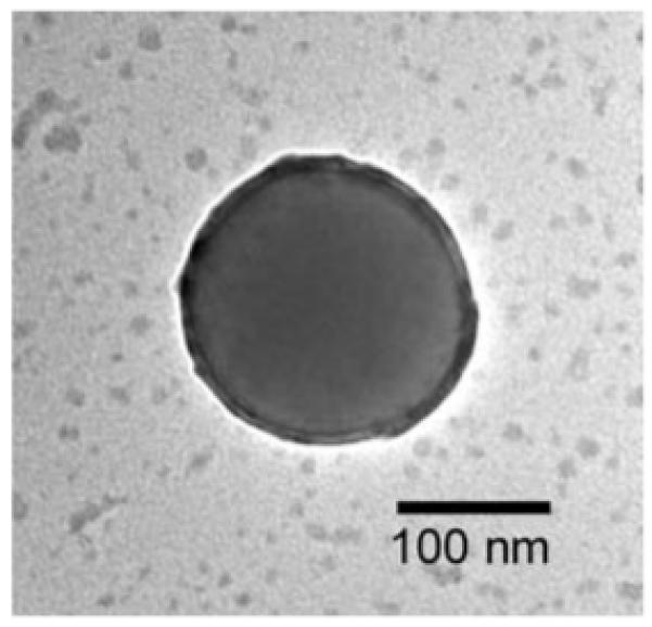
TEM image of a 180 nm PS colloidal particle incubated in a PVA solution. An ∼10 nm layer of PVA appears adsorbed to the particle surface.
The thickness of the PVA layer adsorbed onto a polystyrene colloidal particle depends on the properties of the solution, the concentration of the PVA, and the temperature and the nature of the particles (size, composition, cross-linking, surface charge, and even the prevalent counterion).22 The layer thickness we observed correlates well with Van de Ven’s measurement of the increase in particle radius due to the adsorption of PVA onto polystyrene colloidal particles (5-20 nm) determined by utilizing dynamic light scattering.22 The adsorption causes the concentration of PVA in the vicinity of the particle surface to be higher than it is in the solution. We believe this increased concentration in the vicinity of the colloidal particle facilitates or nucleates the formation of nanocrystallites of PVA.
Thermal Reversibility
We studied the impact of thermal cycling on the diffraction of light by the TGCCA (Figure 6). The sample consisted of 3% PVA in a solution of 50% DMSO and water with approximately 5% colloidal particles by volume. An amount of 0.5 mL of the solution was placed onto a glass plate inside a polyester spacer. Another glass plate sandwiched the sample and squeezed excess solution out of the spacer edges.
Figure 6.
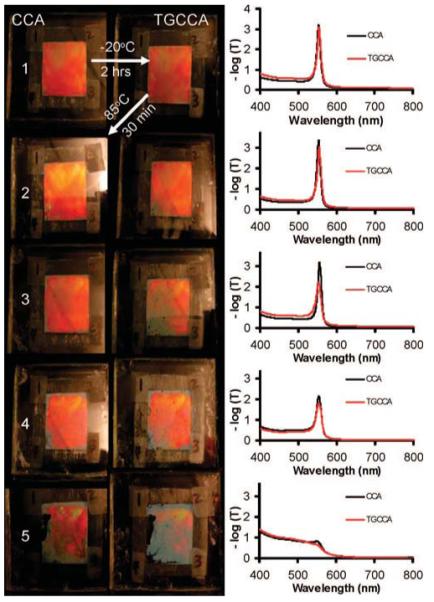
Photographs of CCA (left) thermally cycled to form TGCCA (right). On the right are shown average transmission spectra through four locations in both the CCA (black trace) and the TGCCA (red trace). The colloidal particles disorder, starting at the edges, with increasing thermal cycling.
We measured the transmission of light through the sample to probe ordering of the CCA in both the liquid and the gel phase. We first placed the sample in a -20 °C bath for 2 h, which caused the CCA to gel and form a TGCCA. After the sample returned to room temperature, we took a photograph and measured spectra. We then heated the sample to 85 °C for 30 min, causing the TGCCA to melt into a CCA. After returning to room temperature, another photograph was taken and additional spectra measured. The photographs and spectra after five thermal cycles are shown in Figure 6.
Initially, the diffraction spectra did not change as the CCA gelled into a TGCCA. (Figure 6, row 1). The black and red traces are nearly identical. After heating to 85 °C, the CCA and the TGCCA spectra and photographs remained very similar.
Upon cooling the sample and forming a TGCCA for the second cycle, disorder becomes evident in the lower lefthand corner of the sample. Heating the sample causes the gel to melt and the size of the disordered regions increased within the sample and around the edges. Upon cooling the sample to reform the TGCCA, the lower left portion of the sample becomes increasingly disordered and the diffraction peak height decreased. The sample becomes increasingly disordered with additional thermal cycling until only small regions within the sample continued to diffract.
Figure 6 shows that the sample can be thermally cycled between the liquid and solid state but that multiple cycles negatively impact the diffraction. The diffraction decreases at the edge of the cell suggest that the leaching of ionic impurities from the edge adhesive is responsible for the disorder.
Comparison of TGCCA to Photopolymerized pAMD PCCA Ordering
Figure 7 compares the transmission spectra of a TGCCA to that of a typically prepared pAMD photopolymerized PCCA; each gel was ∼100 μm thick and made with the same 110 nm diameter colloidal particles. Both the TGCCA and the photopolymerized PCCA were made by injecting the respective precursor CCA solutions between quartz plates separated by a 100 μm parafilm spacer. The TGCCA’s diffraction peak (fwhm) was narrower at 17 nm compared to the 25 nm bandwidth for the photopolymerized pAMD PCCA. The standard deviation of the TGCCA diffraction peak maxima between measurements at different positions was found to be σ = 1.8 nm, and the standard deviation of the photopolymerized PCCA was found to be σ = 3.0 nm. The fwhm (bandwidth) expected for a CCA made from 110 nm is expected to be approximately 14 nm according to dynamical Bragg diffraction theory.23 Thus, both the TGCCA and the PCCA bandwidths are larger than expected.
Figure 7.
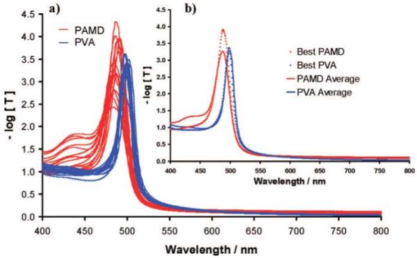
(a) Sixteen transmission spectra were taken of a single photopolymerized PCCA and a single TGCCA. Each spectrum comes from a different 9 × 9 mm area of the PCCA and TGCCA. (b) The average and best of the 16 spectra.
Figure 7b shows the average diffraction spectrum and the narrowest single diffraction spectrum for both the PVA TGCCA and the photopolymerized polyacrylamide PCCA. The PCCA shows much more variability in diffraction between different regions. The best PCCA region shows a much higher diffraction than the TGCCA. However, the poorer PCCA regions display a diffraction shoulder. A perfect fcc lattice, where the 111 planes are oriented perpendicular to the incident light, would show no diffraction until approximately half the wavelength of light diffracted by the 111 planes (∼250 nm). Thus, both the PCCA and the TGCCA are imperfect CCA. The overall narrower diffraction bandwidth of the TGCCA indicates superior ordering.
Cross-Linking the Hydrogel
Thermoreversible gelation results in PVA nanocrystallite physical cross-links that melt at higher temperatures. To create a covalently cross-linked hydrogel, we used glutaraldehyde to cross-link the PVA hydroxyls. We explored two different concentrations of cross-linking reagents and monitored the impact of different cross-link concentrations by removing pieces of the sample at different reaction times and transferring them into pure water. The samples were then heated to 85 °C for 30 min.
PVA TGCCA without covalent cross-links dissolve very rapidly at 85 °C because the nanocrystallite cross-links melt and dissolve. The cross-link density determines the equilibrium hydrogel volume, which we monitor by measuring the wavelength of the diffracted light (Figure 8).
Figure 8.
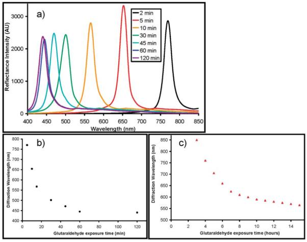
(a) Room-temperature diffraction spectra of TGCCA cross-linked by 1.5% glutaraldehyde solution after melting PVA physical cross-links. The diffraction peak wavelength is a function of the cross-linking time in (b) 1.5% and (c) 0.15% glutaraldehyde.
Figure 8a shows the diffraction spectra from samples removed at different times from a 1.5% glutaraldehyde cross-linking solution, whereas parts b and c of Figure 8 show the dependence of the diffraction on reaction time for cross-link formation in 1.5% and 0.15% glutaraldehyde solutions.
With 1.5% glutaraldehyde, the cross-linking reaction occurs quickly and 2 min was sufficient to form a stable hydrogel, which did not dissolve upon heating. After 60 min of reaction the 1.5% glutaraldehyde cross-linked hydrogel stops blue-shifting. This probably indicates that the 50-fold excess glutaraldehyde cross-linked every PVA hydroxyl group after ∼60 min in the 1.5% glutaraldehyde solution.
A thermally stable hydrogel formed in 3 h with 0.15% glutaraldehyde. As with the higher concentration of glutaraldehyde, the diffraction wavelength blue-shifts with increasing reaction times; however, the cross-linking reaction is slower (note that the abscissa is in units of h).
Functionalization of the Hydrogel
We can prepare a TGCCA chemical sensor by attaching chemical recognition groups to the hydrogel. We covalently cross-linked a 3 cm × 3 cm × 100 μm TGCCA by using a 0.15% glutaraldehyde solution as described above. We then reacted succinic anhydride with the PVA hydroxyls to functionalize the TGCCA with carboxylates. These pendant carboxylic acids make the TGCCA sensitive to pH.24 We also further modified the carboxylated TGCCA with amines using carbodiimide chemistry to link 3-AMP to the carboxylates.
Figure 9 shows both the diffraction spectra and the titration behavior for carboxylated and aminated TGCCA. The low-pH TGCCA shows a peak maximum at ∼445 nm which redshifts to ∼490 nm as the pH increases to pH = 6. The midpoint of the titration curve indicates an effective TGCCA carboxylate pKa ∼ 3.5. For the amine-coupled TGCCA we see a similar titration curve but with a pKa ∼ 9.6. In the absence of TGCCA functionalization we observe little pH dependence of the diffraction.
Figure 9.
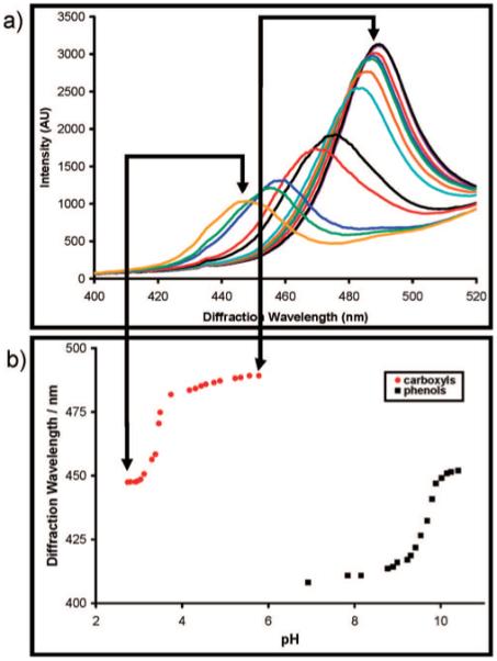
(a) Diffraction spectra for a TGCCA functionalized with carboxylic acid groups exhibits a blue-shift in its diffraction wavelength as the carboxylate is protonated. (b) The titration curves for a carboxyl and 3-aminophenol functionalized TGCCA.
Conclusions
We describe the reversible synthesis of a new type of CCA-based material made by embedding a CCA within a physically cross-linked PVA hydrogel. PVA hydrogels are nontoxic, biocompatible, mechanically robust, and elastic. The TGCCA diffraction is similar to that of our previously developed photopolymerized PCCA. The TGCCA can be irreversibly covalently cross-linked using glutaraldehyde. We demonstrated that the cross-linked TGCCA can be made responsive to chemical stimuli by functionalizing the hydrogel hydroxyl groups. We monitored diffraction of carboxyl or amine functionalized TGCCA as a function of the pH and found that the diffraction wavelength titrates with the pKa of the functional group. We also demonstrated that the TGCCA could be fabricated in arbitrarily large volumes and shapes. Our new method fabricates inexpensive homogeneously diffracting chemically modifiable TGCCA.
CM801519X
References
- (1).John S. Phys. Rev. Lett. 1987;58:2486–2489. doi: 10.1103/PhysRevLett.58.2486. [DOI] [PubMed] [Google Scholar]
- (2).Yablonovitch E. J. Phys., Colloq. 1987;C5:C5-615–C5-616. [Google Scholar]
- (3).Joannopoulos JD, Meade RD, Winn JN, editors. Photonic Crystals: Molding the Flow of Light. 1995. p. 137. [Google Scholar]
- (4).(a) Asher SA, Flaugh PL, Washinger G. Spectroscopy. 1986;1:26–31. [Google Scholar]; (b) Carlson RJ, Asher SA. Appl. Spectrosc. 1984;38:297–304. [Google Scholar]
- (5).Holtz J, Weissman J, Pan G, Asher SA. MRS Bull. 1998;23:44–50. [Google Scholar]
- (6).Asher SA, Holtz JH, Liu L, Wu Z. J. Am. Chem. Soc. 1994;116:4997–4998. [Google Scholar]
- (7).(a) Holtz JH, Asher SA. Nature. 1997;389:829–832. doi: 10.1038/39834. [DOI] [PubMed] [Google Scholar]; (b) Holtz JH, Holtz JSW, Munro CH, Asher SA. Anal. Chem. 1998;70:780–791. [Google Scholar]
- (8).(a) Lee K, Asher SA. J. Am. Chem. Soc. 2000;122:9534–9537. [Google Scholar]; (b) Alexeev VL, Goponenko A, Sharma AC, Lednev I, Wilcox C, Finegold D, Asher SA. J. Am. Chem. Soc. 2003;125:3322–3329. doi: 10.1021/ja021037h. [DOI] [PubMed] [Google Scholar]; (c) Alexeev VL, Sharma AC, Goponenko AV, Das S, Lednev IK, Wilcox CS, Finegold DN, Asher SA. Anal. Chem. 2003;75:2316–2323. doi: 10.1021/ac030021m. [DOI] [PubMed] [Google Scholar]; (d) Sharma AC, Jana T, Kesavamoorthy R, Shi L, Virji M, Finegold DN, Asher SA. J. Am. Chem. Soc. 2004;126:2971–2977. doi: 10.1021/ja038187s. [DOI] [PubMed] [Google Scholar]; (e) Asher SA. In: Nanoparticles: Building Blocks for Nanotechnology. Rotello VM, editor. Kluwer; New York: 2004. pp. 145–172. [Google Scholar]
- (9).Kimble KW, Walker JP, Finegold DN, Asher SA. Anal. Bioanal. Chem. 2006;385(4):678–685. doi: 10.1007/s00216-006-0453-y. [DOI] [PubMed] [Google Scholar]
- (10).Kaneo Y, Hashihama S, Kakinoki A, Tanaka T, Nakano T, Ikeda Y. Drug Metab. Pharmacokinet. 2005;20(6):435–442. doi: 10.2133/dmpk.20.435. [DOI] [PubMed] [Google Scholar]
- (11).Peppas NA, Hilt JZ, Khademhosseini A, Langer R. Adv. Mater. 2006;18:1345–1360. [Google Scholar]
- (12).Nuttelman CR, Henry SM, Anseth KS. Biomaterials. 2002;23:3617–3626. doi: 10.1016/s0142-9612(02)00093-5. [DOI] [PubMed] [Google Scholar]
- (13).Lozinsky VI, Galaev IY, Plieva FM. Trends Biotechnol. 2003;21(10):445–451. doi: 10.1016/j.tibtech.2003.08.002. [DOI] [PubMed] [Google Scholar]
- (14).Hyon S-H, Cha W-I, Ikada Y. Polym. Bull. 1989;22:119–122. [Google Scholar]
- (15).Hassan CM, Peppas NA. Macromolecules. 2000;33:2472–2479. [Google Scholar]
- (16).Takeshita H, Kanaya T, Nishida K, Kaji K. Macromolecules. 2001;34:7894–7898. [Google Scholar]
- (17).Reese CE, Guerrero CD, Weissman JM, Lee K, Asher SA. J. Colloid Interface Sci. 2000;232:76–80. doi: 10.1006/jcis.2000.7190. [DOI] [PubMed] [Google Scholar]
- (18).SIGMACOTE product information sheet. http://www.sigmaaldrich.com/sigma/product%20information%20sheet/sl2pis.pdf.
- (19).Hoshino H, Okada S, Urakawa H, Kajiwara K. Polym. Bull. 1996;37:237–244. [Google Scholar]
- (20).Young T, Chuang W. J. Membr. Sci. 2002;210(2):349–359. [Google Scholar]
- (21).Takahashi H, Kanaya T, Nishida K, Kaji K. Polymer. 2003;44:4075–4078. [Google Scholar]
- (22).Van den Ven TGM. Adv. Colloid Interface Sci. 1994;48:121–140. [Google Scholar]
- (23).Rundquist PA, Photinos P, Jagannathan S, Asher SA. J. Chem. Phys. 1989;91:4932. [Google Scholar]
- (24).Goponenko AV, Asher SA. J. Am. Chem. Soc. 2005;127:10753. doi: 10.1021/ja051456p. [DOI] [PubMed] [Google Scholar]