

Abstract
Objective
To test the efficacy of phase-sensitive x-ray imaging for intact synovial joints, whereby refraction effects, along with the attenuation of conventional radiography, can be exploited.
Design
Intact cadaveric human knee joints were imaged, in the computed tomographic mode, using an analyzer based x-ray system at the National Synchrotron Light Source, Brookhaven National Laboratory. A collimated fan beam of 51 keV X-rays was prepared by a silicon [1,1,1 reflection] double-crystal monochromator. The x-ray beam transmitted through the specimen was imaged after diffraction in the vertical plane by means of the analyzer crystal with the analyzer crystal tuned to its half-reflectivity point (6.5 microradians). A two-dimensional filtered backprojection (FBP) algorithm was used for reconstructing transverse slices of images.
Results
The resulting images demonstrate simultaneous soft-tissue and bone contrast at a level that has not been achieved previously. Identifiable structures include articular cartilage, cruciate ligaments, loose connective tissue, menisci, and chondrocalcinosis.
Conclusion
Phase-sensitive x-ray imaging using an analyzer-based system renders exceptionally high quality images of soft and hard tissues within synovial joints, with high contrast and resolution, and thus holds promise for the eventual clinical utility.
Introduction
The imaging of soft tissues and their associated pathologies is problematic in that they lack adequate contrast for visualization with conventional radiography. This is of concern in the study of degenerative joint diseases, such as osteoarthritis, in which cartilage changes can only be visualized once there is joint space narrowing and thus patent cartilage loss. Thus any attempts to further develop x-ray-based technologies are warranted. We have previously shown that the contrast generated by analyzer-based phase-sensitive imaging1,2 (called diffraction enhanced imaging or DEI in our previous work) renders high quality, nearly scatter-free planar images in which soft and skeletal tissues are simultaneously visible3,4,5,6,7. This is made possible by harnessing the information garnered through the shift in phase as x-rays are refracted at tissue borders within the subject.
In phase-sensitive imaging contrast is dependent upon the x-ray attenuation from absorption and scattering, as with standard radiography, but it additionally relies on the angular deviation of the incident x-ray beam as it is transmitted through the sample. Because this technique also virtually eliminates x-ray scatter, image contrast is greatly enhanced4,5,6,7,8. Our phase-sensitive imaging technology is analyzer-based (AB imaging, or ABI) whereby the angular sensitivity of Bragg diffraction from perfect crystals is converted into intensity variations in the shape of a curve referred to as the rocking curve8,9,10. From these intensity variations, properties such as x-ray attenuation, refraction, and ultra-small-angle scattering 8,11 can be derived at the microradian level, a sensitivity for tissues of similar densities beyond that of conventional radiography. The shape of the rocking curve is roughly triangular with absorption effects visible on the peak and refraction effects most visible on the half-intensity sides6,8). Because of the translation of x-ray refraction into intensity changes (on the order of microradians), there is a detectable signal amplification within the images.
We previously applied this aspect of the ABI system to the study of cadaveric synovial joints5,6,7 and limbs5 and thus explored its potential for the early diagnosis of degenerative joint disease. However fruitful this work was, it was carried out in the planar mode and thus prohibited full depiction of anatomical structures due to tissue superimposition and subject positioning. Here, we carry this work into the computed tomographic (CT) mode by demonstrating that ABI-CT is efficacious for the imaging of soft and skeletal tissues of cadaveric human knee joints with unsurpassed contrast and resolution. Although this work uses the synchrotron as its x-ray source it demonstrates the potential of ABI and is a necessary first-step in the establishment of baseline parameters for the development of an x-ray tube-based ABI system.
Methods
Specimen Preparation
Five intact cadaveric human knees were obtained within 24 hours of death through the Gift of Hope Organ and Tissue Donor Network with Rush University Medical Center Institutional Review Board Approval. The knees were preserved in formalin prior to imaging as we have previously shown that refraction imaging is not affected by formalin preservation12. The length of time the knees were preserved varied from 2 weeks to several months. As part of another study (not yet published), we also imaged 7 intact cadaveric human knee joints, in the planar mode of analyzer-based imaging at the same energy as the present study (51 keV), both prior to and following formalin preservation and were not able to detect any differences in tissue characteristics between images. For the present study, just prior to imaging, each individual knee was placed in a cylindrical polyethylene container (in the absence of water or any other solution), approximately the size of the knee, and stabilized with packing material at the ends outside the field of view to provide stability during imaging. The container was then sealed with laboratory sealing film (Seal View™, Norton Performance Plastics Corp., Akron, OH) to prevent dehydration of the specimen during imaging.
Imaging
Images were acquired at the X15A beamline at the National Synchrotron Light Source, Brookhaven National Laboratory. A collimated fan beam of 51 keV X-rays was prepared by a silicon [1,1,1 reflection] double-crystal monochromator4 (Fig. 1). Each knee joint was mounted on a scanning stage between the monochromator and a silicon analyzer crystal, and rotated about an axis perpendicular to the plane of the fan beam. The x-ray beam transmitted through the specimen was imaged after diffraction in the vertical plane by means of the analyzer crystal with the analyzer crystal tuned to the half-reflectivity point (6.5 microradians) for its 51 keV, 1,1,1 reflection. For this configuration, the full width at half-maximum of the rocking curve is approximately 13 microradians. Two thousand CT projections in 0.18 ° increments over 360° were collected. Images were acquired with a beam height of 2.2 mm at the location of the knee joint. Images of the knee were obtained at 2000 angular positions to enable CT reconstruction. The field of view contains a region of the knee extending from the level of the tibial tuberosity to the level of the base of the patella, thus covering the tibiofemoral and patellofemoral joints.
Figure 1.
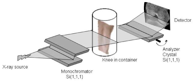
Schematic diagram of the analyzer-based imaging set-up showing the double crystal monochromator and analyzer crystal, the essential elements of the technology.
The detector (X-Ray Imager-VHR 150 camera system, Photonic Science Ltd. UK; 4008 pixels in the horizontal dimension and by 2672 in the vertical dimension) has a pixel size of 28.1 μm, thus each 2.2 mm vertical height scan through the knee generated 78 separate planar images from which CT volumes were reconstructed. In order to image the desired field of view for the knee, full sets of 2.2 mm vertical height projection images were acquired, then the sample stage was vertically translated 1.7 mm and another full set of projection images was acquired. This was repeated until the full field of view was imaged. Exposure time was 0.5 s per projection image. The reproducibility of the images was maintained by monitoring the intensity of the diffracted x-rays by an analyzer crystal just prior to imaging. Input data consist of the number of sample images taken, the number images taken with the shutter closed (background data), and the number of images without the sample (air scan, for image normalization). Average radiation dose in the knee joint was approximately 0.25 Gy, and total imaging time was approximately 23 hours.
Individual projection images were opened in Interactive Data Language (IDL; ITT Visual Information Solutions, Boulder, CO). After background and air correction, the data was two by two rebinned, such that each pixel in the projection image was 56.2 by 56.2 μm. A standard filtered backprojection, using a Hann filter (cutoff frequency of 0.5) was used to generate a volumetric data set. Each voxel in the reconstructed data set represents a measure of the total attenuation, extinction and refraction within the corresponding volume, but with single angle ABI, it is not possible to separate the three contrast mechanisms (i.e. it is not possible to know how much each contrast mechanism contributes to the total contrast). Results for single angle ABI-CT have been previously reported by Keyriläinen, et al.13. While we have developed more-sophisticated iterative reconstruction procedures for ABI 14, these were not necessary due to the high signal-to-noise ratio in the acquired data. Prior to reconstruction, the data were rebinned to a voxel size in the reconstructed image of 56.2 μm.
Results
The resulting images demonstrate simultaneous soft-tissue and bone contrast at a level that has not been achieved previously. In the representative transverse slice image shown in Figure 2, the cartilage surrounding the bony femoral condyles displays a combination of smooth surfaces at locations of normal cartilage and abrupt loss of contour in other locations due to the cartilage loss characteristic of osteoarthritis5,7. It also demonstrates how cartilage degeneration, without blatant tissue loss can be identified by the presence of contrast heterogeneity within the tissue5,7. Other visible features include menisci and calcinosis within the articular cartilage. The bony features are seen with clarity.
Figure 2.
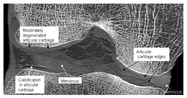
Frontal slice image of a cadaveric human knee joint showing soft tissues and bone. Articular hyaline cartilage and fibrocartilage of the menisci are visible. Contrast heterogeneities within the articular cartilage are representative of cartilage degeneration as has been shown in our previous planar work. These contrast heterogeneities occur where the normally smooth articular cartilage edge is disrupted within an area, thus creating numerous edges with new refractive borders.
Figure 3 is a sagittal slice image of the knee in which the articular cartilage of both tibiofemoral and patellofemoral joints is well visualized. Note the calcinosis of the cartilage and meniscus. Also visible are the patellar tendon at the anterior aspect of the knee and muscles and tendons at the posterior aspect. Each of these features is made visible principally due to x-ray refraction at the boundaries of the tissues.
Figure 3.
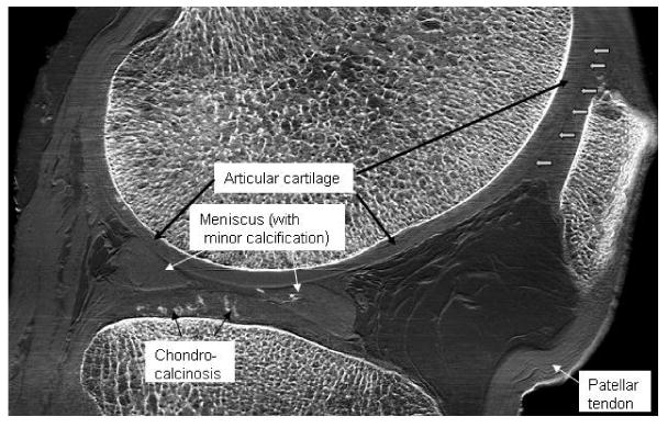
Sagittal slice image of a cadaveric human knee joint. Salient features are labeled. Note that even the collagen fiber bundles of the ACL are identifiable. Boundaries between the cartilages of the patella and of the trochlear surface of the femur are not easily distinguishable in this image due to the angle of these boundaries with respect to the beam; edge enhancement may be lessened when exactly perpendicular to the beam. This can be alleviated by more optimal positioning of the joint prior to imaging. Note the high quality of the bone features simultaneous with soft tissue features, something not possible with MRI.
In Figure 4, the most prominent soft tissue features are the ligaments, tendons, cartilage, and blood vessels. Of note is that the two bands of the anterior cruciate ligament can be distinguished from one another. One particular weakness in this imaging, however, is seen in the cartilage imaging of the patellofemoral joint. Because this implementation of ABI is sensitive only to wavefield tilts in one direction, cartilage edges run perpendicular to this direction are not well defined. This can be mitigated by judicious positioning of the joint, or eliminated entirely by imaging at two orthogonal orientations.
Figure 4.
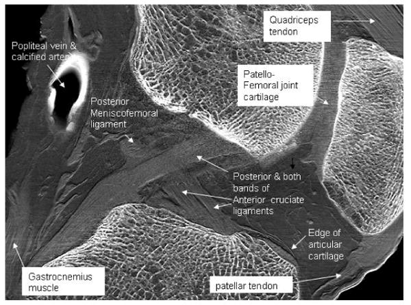
Sagittal slice image of a cadaveric human knee with salient features labeled. The border of the cartilage of the femoral trochlear surface is identified at the open arrows. Collagen fiber bundles of the patellar tendon are visible. Note the clarity of the cortical and trabecular bone simultaneous with soft tissue features.
Discussion
The development of spectroscopy and computed axial tomography not withstanding, the widespread clinical application of the more basic principles of x-rays, i.e. properties other than attenuation, have not changed significantly over the years. For example, imaging methods based on the phase shift of x-rays have not been widely used in clinical applications primarily due to the extremely small variations in the magnitude of refractive-index at x-ray wavelengths. In the present study we have taken advantage of these small refractive index variations through the use of a perfect silicon crystal placed between the subject and the detector which amplifies resultant intensity differences. It is important that new imaging modalities such as this be explored and further developed because the ability to depict the characteristics of both soft tissue and bone with high contrast and spatial resolution is lacking. Magnetic-resonance imaging (MRI) is widely used for imaging of soft tissue 15,16,17,18, but MRI currently does not yield sufficient spatial resolution for visualization of subtle pathologies, such as early stages of cartilage degeneration, may be difficult to interpret in terms of pathology18, and is not an effective method for the simultaneous visualization of soft tissue and bone pathology. Conventional x-ray imaging (radiography) allows visualization of bone clearly, but renders cartilage virtually invisible, and is incapable of demonstrating any significant details of soft tissues such as tendons and ligaments. Here, we have shown that ABI, using x-rays, produces extremely high quality images exhibiting exquisite detail of soft and hard tissue components and their pathologies.
The fact that osteoarthritis is a condition affecting both bone and cartilage makes it clear that the elucidation of pathologies in both of these tissues simultaneously is important in the complete diagnosis and treatment of the specific state of the condition. This optimal simultaneous imaging of soft and skeletal tissues is not possible with current clinical MRI systems19, in part because the MR signal of the synovial fluid is close to that of the cartilage, thereby making it difficult to distinguish between the two. In contrast, ABI readily delineates the border between cartilage and other tissues due to ABI's high sensitivity to refraction effects at this interface, notably without any use of contrast agents. Of further interest is that ABI allows the identification of pathological calcifications to which MRI is relatively insensitive20. As calcifications such as those present with metabolic disease become more prevalent in our society, early diagnosis will prove beneficial.
An issue that requires addressing is that of the formalin preservation of the joints prior to imaging. We previously carried out experiments to determine the effect of preservation on planar ABI of cadaveric human knee joints and found no difference between the ABI images before and after preservation. The reason for this is that preservation does not affect the x-ray refraction at tissue boundaries: the main parameter upon which our ABI for the present study is based.
Considering the efficiency and capabilities of contemporary x-ray CT, it is difficult to appreciate that the first CT scanner, developed by Hounsfield in 1972, required several hours for acquisition of the raw data for a single CT slice. Every new technology has its primitive inception--a necessary first step. Here, we have presented a paradigm illustrating the extraordinary degree to which ABI renders images of calcified and uncalcified tissues simultaneously and with unprecedented contrast and resolution. Our images clearly allow the visualization of soft and hard tissues simultaneously, a result primarily of the ability to improve contrast and exploit x-ray refraction at tissue boundaries. This is accomplished through two major factors based on the inherent properties of x-rays First, additional contrast is gained by preventing the majority of x-ray scatter from reaching the detector, a source of image degradation in conventional radiography. This is achieved by virtue of the angular sensitivity of the analyzer crystal, the distinguishing feature of ABI8,21,22,23. Secondly, the analyzer crystal allows detection of refracted x-rays and, thus, high sensitivity for delineating the boundaries between tissues having different refractive indices. Furthermore the resultant increase in contrast is achieved at lower x-ray doses since higher x-ray energies can be applied.
A new generation synchrotron facility is being constructed to replace the current NSLS, which will allow future ABI studies to be performed in much shorter imaging times than is possible with our current system. The ABI setup at the new facility will have the ability to generate even higher energy, and thus lower x-ray dose and will be able to generate images on the order of tens of minutes rather than hours. The techniques must also now be pushed beyond the synchrotron and into a clinical context by optimizing such parameters as x-ray sources, optics, and detectors2. Currently, at least two ABI systems which utilize conventional x-ray tubes in place of a synchrotron are under development by some of the authors of this paper. Although the clinical use of ABI is still in the future its applicability as a pharmaceutical research tool for the study of progression of joint disease is fast approaching. “Past experience has shown, … that when a new imaging technique is capable of providing greater insights into body anatomy and physiology, the technical problems can be, and are, overcome.”24.
Acknowledgments
This work was supported by NIH grant R01 AR48292-05. We thank Miles Wernick, Ph.D. for his intellectual contributions and for contributing to the early preparation of the manuscript.
Footnotes
Author Contributions: JL, ZZ, and DC performed the imaging experiments at the NSLS. JL prepared the specimens, reconstructed the data, and optimized the images with IDL. JM and CM conceived and supervised the project, and CM and DC wrote the manuscript.
Competing Financial Interests: The authors claim no competing financial interests.
Publisher's Disclaimer: This is a PDF file of an unedited manuscript that has been accepted for publication. As a service to our customers we are providing this early version of the manuscript. The manuscript will undergo copyediting, typesetting, and review of the resulting proof before it is published in its final citable form. Please note that during the production process errors may be discovered which could affect the content, and all legal disclaimers that apply to the journal pertain.
References
- 1.Fitzgerald R. Phase-sensitive x-ray imaging. Phys Today. 2000;53:23–7. [Google Scholar]
- 2.Lewis RA. Medical phase contrast x-ray imaging: current status and future prospects. Phys Me Biol. 2004;49:3573–83. doi: 10.1088/0031-9155/49/16/005. [DOI] [PubMed] [Google Scholar]
- 3.Muehleman C, Chapman LD, Kuettner KE, Rieff J, Mollenhauer JA, Masuda K, et al. Radiography of rabbit articular cartilage with diffraction-enhanced imaging. Anat Rec A Discov Mol Cell Evol Biol. 2003;272:392–7. doi: 10.1002/ar.a.10043. [DOI] [PubMed] [Google Scholar]
- 4.Muehleman C, Majumdar S, Issever AS, Arfelli F, Menk RH, Rigon L, et al. X-ray detection of structural orientation in human articular cartilage. Osteoarthritis and Cartilage. 2004;12:97–105. doi: 10.1016/j.joca.2003.10.001. [DOI] [PubMed] [Google Scholar]
- 5.Li J, Zhong Z, Lidtke R, Kuettner KE, Peterfy C, Aliyeva E, et al. Radiography of soft tissue of the foot and ankle with diffraction enhanced imaging. J Anat. 2003;202:463–70. doi: 10.1046/j.1469-7580.2003.00175.x. [DOI] [PMC free article] [PubMed] [Google Scholar]
- 6.Wernick MN, Wirjadi O, Chapman D, Zhong Z, Galatsanos NP, Yang Y, et al. Multiple-image radiography. Phys Med Biol. 2003 Dec 7;48(23):3875–95. doi: 10.1088/0031-9155/48/23/006. [DOI] [PubMed] [Google Scholar]
- 7.Li J, Williams JM, Zhong Z, Kuettner KE, Aurich M, Mollenhauer J, et al. Reliability of diffraction enhanced imaging for assessment of cartilage lesions, ex vivo. Osteoarthritis and Cartilage. 2005;13:187–97. doi: 10.1016/j.joca.2004.11.003. [DOI] [PubMed] [Google Scholar]
- 8.Chapman D, Thomlinson W, Johnston RE, Washburn D, Pisano E, Gmür N, et al. Diffraction enhanced x-ray imaging. Phys Med Biol. 1997;42:2015–25. doi: 10.1088/0031-9155/42/11/001. [DOI] [PubMed] [Google Scholar]
- 9.Bravin A, Keyrilainen J, Fern M, Fiedler S, Nemoz1 C. High-resolution CT by diffraction-enhanced x-ray imaging: mapping of breast tissue samples and comparison with their histo-pathology. Phys Med Biol. 2007;52:2197–211. doi: 10.1088/0031-9155/52/8/011. [DOI] [PubMed] [Google Scholar]
- 10.Coan P, Mollenhauer J, Wagner A, Muehleman C, Bravin A. Analyzer-based imaging technique in tomography of cartilage and metal implants: A study at the ESRF. Eur J Radiol. 2008 doi: 10.1016/j.ejrad.2008.04.036. [DOI] [PMC free article] [PubMed] [Google Scholar]
- 11.Wernick MN, Wirjadi O, Chapman D, Zhong Z, Galatsanos NP, Yang Y, et al. Multiple-image radiography. Phys Med Biol. 2003;48:3875–95. doi: 10.1088/0031-9155/48/23/006. [DOI] [PubMed] [Google Scholar]
- 12.Mollenhauer J, Aurich ME, Zhong Z, Muehleman C, Cole AA, Hasna M, et al. Diffraction-enhanced X-ray imaging of articular cartilage. Osteoarthritis Cartilage. 2002;10:163–71. doi: 10.1053/joca.2001.0496. [DOI] [PubMed] [Google Scholar]
- 13.Keyriläinen J, Fernández M, Karjalainen-Lindsberg ML, Virkkunen P, Leidenius M, von Smitten K, et al. Toward high-contrast breast CT at low radiation dose. Radiology. 2008;249:321–7. doi: 10.1148/radiol.2491072129. [DOI] [PubMed] [Google Scholar]
- 14.Brankov J, Marquet B, Wernick MN. IEEE Intl Symp Biomed Imaging. 2006. Noise and sampling for multiple-image radiography; pp. 1232–5. [Google Scholar]
- 15.Kijowski R, Tuite M, Passov L, Shimakawa A, Hu H, Reeder SB. Cartilage imaging at 3.0T with gradient refocused acquisition in the steady-state (GRASS) and IDEAL fat-water separation. J Magn Reson Imaging. 2006;28:167–74. doi: 10.1002/jmri.21414. [DOI] [PMC free article] [PubMed] [Google Scholar]
- 16.Kuhl CK, Träber F, Schild HH. Whole-body high-field-strength (3.0-T) MR Imaging in Clinical Practice. Part I. Technical considerations and clinical applications. Radiology. 2008;246:675–96. doi: 10.1148/radiol.2463060881. [DOI] [PubMed] [Google Scholar]
- 17.Augat P, Eckstein F. Quantitative Imaging of Musculoskeletal Tissue. Annu Rev Biomed Eng. doi: 10.1146/annurev.bioeng.10.061807.160533. In Press. [DOI] [PubMed] [Google Scholar]
- 18.Burstein D, Gray ML. Is MRI fulfilling its promise for molecular imaging of cartilage in arthritis? Osteoarthritis and Cartilage. 2006;11:1087–90. doi: 10.1016/j.joca.2006.07.001. [DOI] [PubMed] [Google Scholar]
- 19.Griffin N, Joubert I, Lomas DJ, Bearcroft PWP, Dixon AK. High resolution imaging of the knee on 3-Tesla MRI: a pictorial review. Clin Anat. 2008;21:374–82. doi: 10.1002/ca.20632. [DOI] [PubMed] [Google Scholar]
- 20.Abreu M, Johnson K, Chung CB, De Lima JE, Jr, Trudell D, Terkeltaub R, et al. Calcification in calcium pyrophosphate dihydrate (CPPD) crystalline deposits in the knee: anatomic, radiographic, MR imaging, and histologic study in cadavers. Skeletal Radiol. 2004;33:392–398. doi: 10.1007/s00256-004-0767-9. [DOI] [PubMed] [Google Scholar]
- 21.Hasnah MO, Parham C, Pisano ED, Zhong Z, Oltulu O, Chapman D. Mass density images from the diffraction enhanced imaging technique. Med Phys. 2005;21:549–52. doi: 10.1118/1.1852794. [DOI] [PubMed] [Google Scholar]
- 22.Hasnah MO, Zhong Z, Oltulu O, Pisano E, Johnston RE, Sayers D, et al. Diffraction enhanced imaging contrast mechanisms in breast cancer specimens. Med Phys. 2002;29:2216–21. doi: 10.1118/1.1507782. [DOI] [PubMed] [Google Scholar]
- 23.Kiss MZ, Sayers DE, Zhong Z. Measurement of image contrast using diffraction enhanced imaging. Phys Med Biol. 2003;48:325–340. doi: 10.1088/0031-9155/48/3/304. [DOI] [PubMed] [Google Scholar]
- 24.Dendy P, Harrison R. Commentary: Diffraction Enhanced Imaging. Brit J Radiol. 2003;76:289. doi: 10.1259/bjr/19345871. [DOI] [PubMed] [Google Scholar]