Tissue engineering is a promising approach to the development of biological substitutes that regenerate, replace, maintain, or improve the function of damaged tissues. Among various topics related to tissue engineering, the structures and properties of the scaffolds have been studied extensively in the context of material science and biomedical engineering. There are a number of generic requirements for the scaffold: 1) the material used for fabricating the scaffold must be biocompatible and biodegradable, together with positive responses from the seeded cells; 2) the scaffold should contain a network of pores, and favorably in the form of 3D interconnected architecture; and 3) the scaffold should have proper mechanical properties to suit the specific applications, including the generation of cartilage, bone, artificial blood vessel, among others.[1]
In order to generate a well-defined scaffold, numerous methods have been proposed, including emulsion freeze drying,[2] high pressure processing,[3] particulate leaching,[4] gas foaming,[5] phase separation,[6] and electrospinning.[7] However, most of these methods are rather limited in terms of capability and feasibility. For example, the electrospinning method can hardly be extended to fabricate truly 3D scaffolds. Many of the other methods typically lead to the formation of irregular pore sizes, shapes, and structures, as well as poor connectivity.
The pore size and structure of a scaffold are known to play a vital role in cell culture because they are responsible for not only the adhesion, migration, and distribution of cells, but also for the exchange of nutrients and metabolite wastes. Despite extensive efforts to control the pore sizes and structures, the issues related to uniformity and interconnectivity are yet to be solved as pointed out by many researchers.[8] In addressing these issues, the inverse opal structure can be considered as an ideal system, which has the most uniform pore size and regular 3D interconnectivity. Several groups have already shown the potential of an inverse opal as scaffold for 3D tissue engineering.[9] However, the used materials, silicate and polyacrylamide, are not biodegradable and can thus limit their potential use in clinical applications.
Here we describe a technique for fabricating chitosan inverse opal scaffolds characterized by a biodegradable material, uniform pore size, well-controlled interconnectivity, and nanofibrous texture on the wall surface. We used uniform poly(caprolactone) (PCL) microspheres, prepared using a simple fluidic device, as the template.[10] Chitosan was chosen as a scaffold material because of its unique nanofibrous structure that typically develops during freeze-drying, as well as its nontoxic, anti-microbial, biocompatible, and biodegradable properties. Moreover, chitosan does not need a cross-linking procedure because it is only soluble in an acidic solution. We have also evaluated the potential use of the chitosan inverse opal as 3D scaffolds in the culture of preosteoblastic cells.
The procedure for fabricating the chitosan inverse opal scaffold includes three major steps: production of uniform PCL micro-spheres; fabrication of a cubic close packed (ccp) lattice; and development of an inverse opal structure by infiltration and selective dissolution of PCL template. Previously, we have developed a simple fluidic device fabricated with a PVC tube, a 26G needle, and a glass capillary tube for producing uniform microspheres with sizes ranging from 30 to 250 µm and coefficients of variance less than 5%.[10] In the present work, we fabricated the inverse opal scaffolds with uniform PCL microspheres of (147.7 ± 1.4) µm in average diameter.
The commonly used methods for assembling submicrometer-sized particles into ccp lattices involve the use of gravitational, electrostatic, or capillary forces, and physical confinement with pressure and flow.[11] For particles with diameters >10 µm, several groups have reported ccp lattices that were achieved using a combination of agitation, solvent evaporation, and/or variation of the viscosity of the dispersion medium.[9b,c,12] We employed the sedimentation-evaporation method to assemble the PCL microspheres into ccp lattices. In a typical procedure, the PCL microspheres dispersed in water were allowed to settle to the bottom of a 50mL centrifuge tube because the density of PCL (1.1 g mL−1) is higher than that of water (1.0 g mL−1). By gently shaking the sample, the PCL microspheres could be arranged into a closely packed structure during water evaporation. When ethanol was used as the dispersion medium, partially ordered structures with defects were often obtained due to fast evaporation of the dispersion medium.[9a]
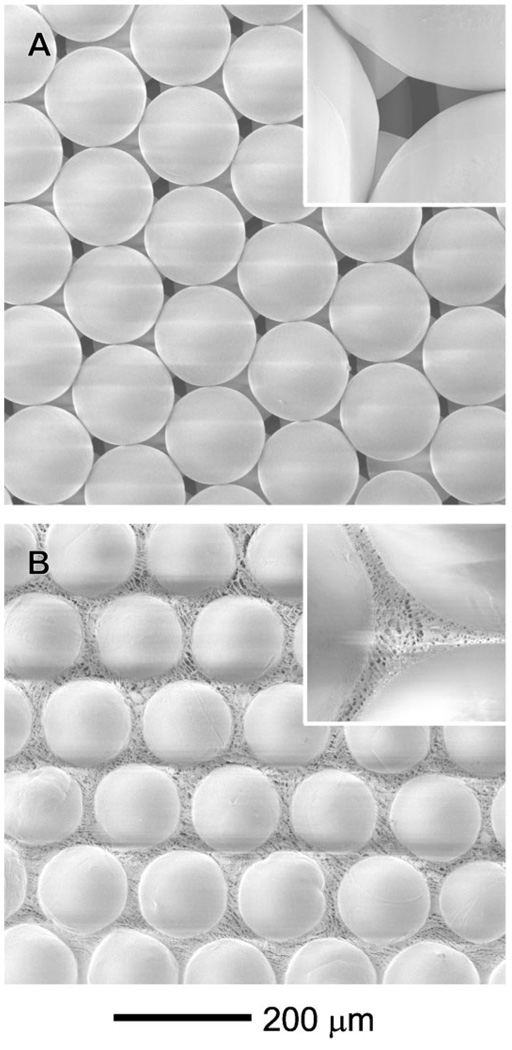
Figure 1A shows a scanning electron microscopy (SEM) image of a ccp lattice formed from the PCL microspheres. Note that each PCL microsphere was in physical contact with its neighboring microspheres, which is critical to the formation of a three-dimensionally interconnected network of pores in the inverse opal scaffold. Prior to infiltration of chitosan solution, heat treatment is needed to make the ccp lattice more robust by fusing the microspheres at their junctions. By placing the ccp lattice in an oven heated at 45 °C (lower than the melting point of PCL, 60 °C) for 50 min, we could obtain robust ccp lattice in the form of a pellet without changing the surface morphology of the microspheres. We could also control the area of physical contact between adjacent microspheres by varying the conditions for heat treatment, and thus vary the size of windows interconnecting pores in the inverse opal scaffold. It is difficult to infiltrate the chitosan solution into the ccp lattice pellet under ambient conditions because of the high viscosity of chitosan solution and hydrophobic nature of the PCL microspheres. Therefore, we used the infiltration method developed by Stein and coworkers, which is based on the use of a Büchner funnel connected to vacuum.[13] After dropping a mixture of water and ethanol (5:5, v/v) to wet the surface of the PCL microspheres, we placed the viscous chitosan solution on the top of the ccp lattice pellet, allowing chitosan solution to penetrate into the void space through capillary force under vacuum suction. The ccp lattice pellet with chitosan solution was then frozen at −20 °C for 3 h and finally freeze-dried. Figure 1B shows SEM image of the sample after freeze-drying of the chitosan solution in a ccp lattice pellet. In the voids among the PCL microspheres, a nanofibrous structure was formed by the chitosan due to a phase separation between water and chitosan during freezing at −20 °C. The resultant ccp lattice pellet with chitosan was immersed in ethanol for 1 h to leach out the acetic acid originating from the chitosan solution,[14] and then in dichloromethane (DCM) to remove the PCL microspheres. Afterwards, the chitosan scaffold was soaked in ethanol for 1 h and then water for 1 h. Finally, a chitosan-based inverse opal scaffold was obtained through another step of freeze drying.
Figure 1.
SEM images of A) the ccp lattice of PCL microspheres and B) a freeze-dried sample after infiltration of the chitosan solution.
We have also tried gelatin, collagen, and hyaluronic acid as materials for the scaffolds under conditions similar to the chitosan system. However, the resultant scaffolds were too soft to support the highly porous structures even after cross-linking. In this regard, it is clear that the chitosan scaffold offers a better mechanical property, which is probably related to its crystallinity and low solubility in water at pH > 7. The tensile strength of the porous chitosan scaffold was typically in the range of 30 to 60 kPa.[15]
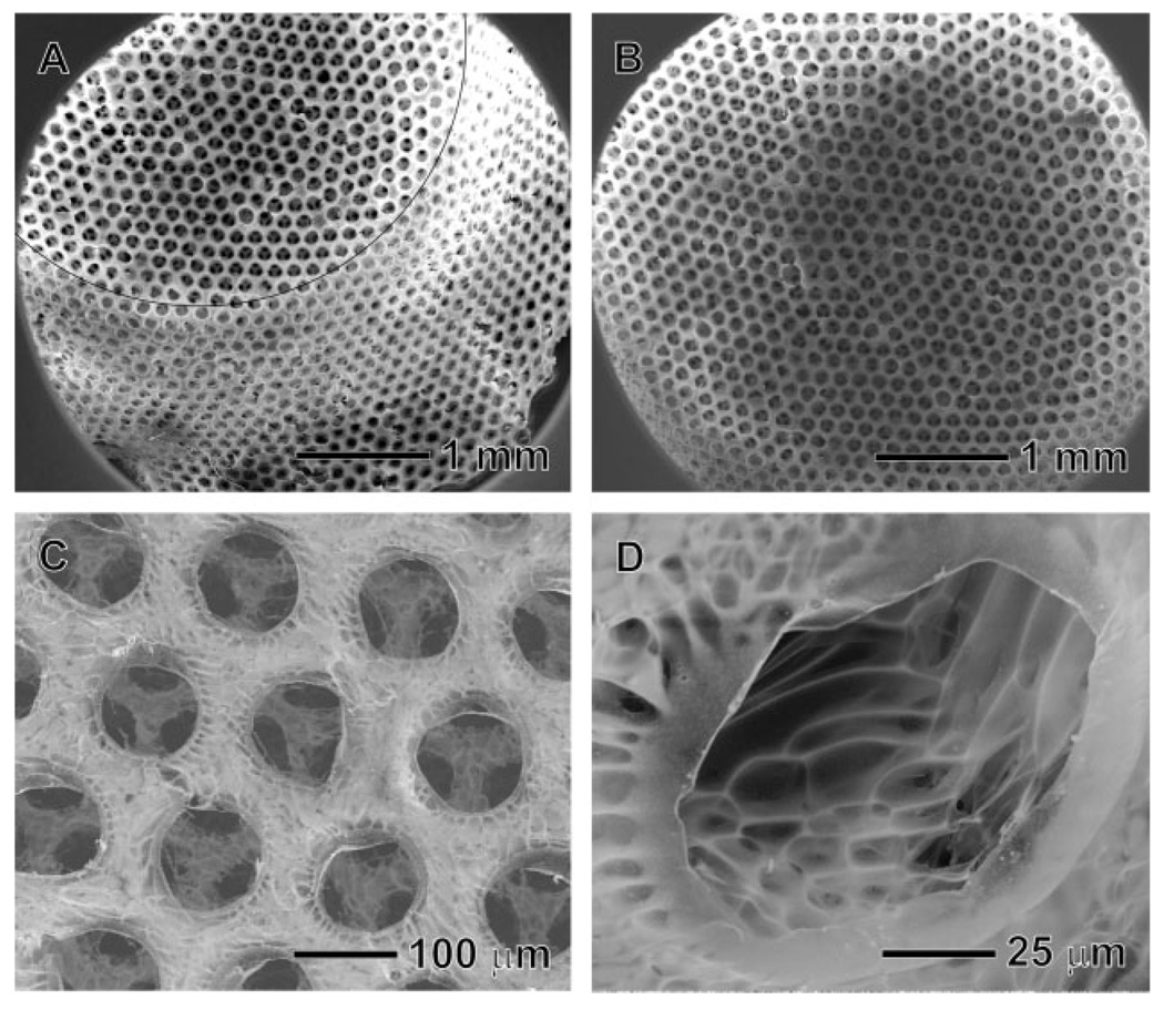
Figure 2 shows SEM images of the inverse opal scaffold that exhibits a uniform interconnected pore structure together with a nanofibrous matrix. The open and ordered pore structure throughout the scaffold will allow cells to easily penetrate into the scaffold, facilitate the exchange of nutrient and metabolite waste, and potentially promote in vivo vascularization.[16] The uniformity of pore size and structure is an important requirement for the scaffold, although it is often neglected in previous studies. In general, scaffold with a uniform pore size can provide a better environment for the cells by providing a completely interconnected structure and the most favorable pore size for the cells. If polydisperse microspheres are used for this process, a pore might have none to three windows connecting with adjacent pores, and this will greatly limit the uniformity of cell seeding on the scaffold, as well as the effective supply of nutrients, diffusion of gases, and removal of metabolic wastes. In addition, many research groups have reported the optimum pore sizes for various kinds of cells or tissues: for example, 5–15 µm for fibroblasts; ≈20 µm for hepatocytes; 70–120 µm for chondrocytes; 40–150 µm for fibroblast binding; 60–150 µm for vascular smooth muscle cell binding; 100–300 µm for bladder smooth muscle cell adhesion and ingrowth; 100–400 µm for bone regeneration, and 200–350 µm for osteoconduction.[17] Although the optimum pore size for each type of cell is often presented by a range of sizes and also sometime controversial, it is clear that each cell lineage has its own favorable size range for the pores. Therefore, the scaffold with a uniform, appropriate pore size for a specific cell type can provide a better environment for the cell culture. Figure 2A and 2B show side and top views of the scaffold, respectively, which had a conical cylinder shape with a diameter of 4 mm at the top surface, 1.5 mm thick, and 6 mm in diameter at the base plane. Figure 2C shows SEM image of the characteristic feature intrinsic to the chitosan scaffold. The nanofibrous matrix of chitosan became less significant at the top surface of the scaffold after solvent extraction. This can be explained as follows. In the course of medium exchange, the fast evaporation of DCM and ethanol at the surface caused some slight dissolution for the chitosan, leading to the formation of a dense structure. Figure 2D shows SEM image of the inner surface of the inverse opal scaffold. The typical nanofibrous structure of the freeze-dried chitosan was found on the inside wall of the pores because this part of the sample was not exposed to air during the exchange of medium, and thus the nanofibrous structure was preserved. These results indicate that we have overcome some of the major problems typically encountered in the fabrication of scaffolds, including the retention of a uniform pore size, a well-interconnected structure, and a nanofibrous matrix.
Figure 2.
SEM images of the chitosan inverse opal scaffold: A) side view, B) top view, C) a magnified view of the top surface, and D) a magnified view of the side wall in a pore. The black line in (A) represents the edge of the scaffold.
We also evaluated the potential use of the chitosan inverse opal scaffolds for tissue engineering by culturing preosteoblastic cells on them. The cells were incubated in a spinner flask together with the scaffolds with gentle stirring at 50 rpm for 3 h, allowing the cells to be seeded onto the scaffold at a density of 1.05 × 10⁵ cells per scaffold. We then used confocal microscopy to follow the attachment and proliferation of the cells on the scaffold. Figure 3A and 3B show confocal microscopy images one day after cell seeding. It is noted that the cells were uniformly distributed over the scaffold. For practical applications, the cell distribution in the scaffold is a very important issue because the region devoid of cells might be a defect after the formation of a specific organ.[18] Figure 3B shows that the cells were immobilized on the inner surface of the pores, where they maintained their round shape for 4 days and they began to spread after 7 days. In Figure 3C, the structure of inverse opal was observed together with the cells adhered to the scaffold. After 14 days, the cells fully spread and proliferated prominently throughout the scaffold as shown in Figure 3E and 3F. It is worth pointing out that the scaffold could maintain its spherical pore structures up to 21 days.
Figure 3.
Confocal microscopy images taken A,B) 1, C) 4, D) 7, E) 14, and F) 21 day(s) after cell seeding on the chitosan inverse opal scaffolds. All the images were obtained at a plane ≈50 µm from the surface into the scaffold.
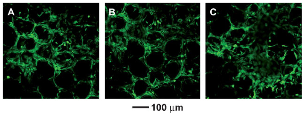
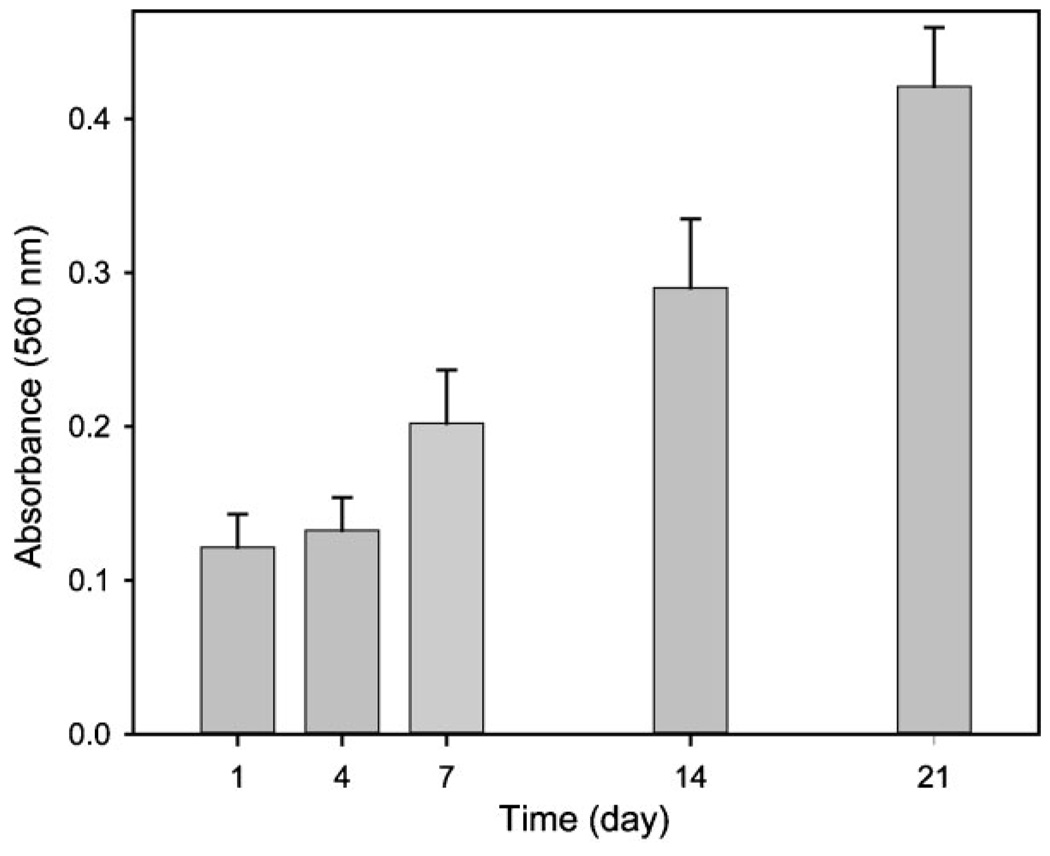
Figure 4 shows confocal microscopy images of the proliferated cells after 21 days of culture at a distance of 0, 50, and 150 µm away from the surface into the scaffold. A number of cells were proliferated inside the scaffold as well as on the surface, clearly indicating that the cells grew in a 3D fashion. We also quantified cell proliferation on the scaffold using MTT assay as shown in Figure 5, where the absorbance at 560nm is proportional to the number of cells. Obviously, the number of cells increased almost 4-fold within 21 days compared to the number of cells after one day. This result implies that the chitosan inverse opal scaffold can provide a suitable environment for cell growth.
Figure 4.
Confocal microscopy images of the proliferated cells at different planes along the vertical direction: A) 0, B) 50, and C) 150 µm from the surface into the scaffold after 21 days of culture.
Figure 5.
Proliferation of MC3T3-E1 cells seeded on the chitosan inverse opal scaffold (n = 5).
In summary, we have successfully demonstrated the fabrication of chitosan inverse opal scaffolds exhibiting a uniform pore size, interconnected network, and nanofibrous matrix, which meets many of the key requirements for tissue engineering. It is worth pointing out that the pore size of the scaffold could be easily tuned by changing the diameter of PCL microspheres. Despite many previous studies, the effect of pore size on cell growth is still controversial.[19] Therefore, the inverse opal scaffolds described in this paper could be used as a model system for in vitro studies of cell culture, and as a class of clinically practical scaffolds for tissue engineering. In the present study, we only demonstrated the fabrication of such inverse opal scaffolds with dimensions in the order of a few millimeters. If needed, however, the same protocols and materials can also easily be extended to fabricate scaffolds with much larger dimensions. In addition, we believe that the fabrication technique could be extended to a variety of other water-soluble or dispersible matrix materials. In the next step, our goal will be the fabrication of hydrophobic inverse opal scaffolds with uniform microparticles made of water-soluble polymers.
Experimental
Materials
Poly(caprolactone) (PCL, Mw ≈ 65 000, Aldrich) and poly(-vinyl alcohol) (PVA, Mw ≈ 13 000–23 000, 98% hydrolyzed, Aldrich) were used to produce the uniform PCL microspheres using a fluidic device. Chitosan (medium Mw, 75–85% deacetylated, Aldrich) was used as the materials for the scaffold. Acetic acid (99.7%), dichloromethane (DCM, 99.0%), and ethanol (99.5%) were purchased from Sigma–Aldrich. The water used in all reactions was obtained by filtering through a set of Millipore cartridges (Epure, Dubuque, IA).
Preparation of Inverse Opal Chitosan Scaffold
Uniform PCL micro-spheres with a diameter of (147.7 ± 1.4) µm were produced using the fluidic device,[10] and then used for fabricating ccp lattice template. A 50mL centrifuge tube was chosen as a container due to the advantage for harvesting. The centrifuge tube with an aqueous suspension of the PCL microspheres (≈1.5 wt %) was sonicated for 10 s, and placed on an orbital shaker set to 80 rpm during the evaporation of water at room temperature. The resultant ccp lattice was placed in an oven heated at 45 °C for 50 min. By adding 5mL of ethanol into the centrifuge tube, the ccp lattice pellet was harvested by spatula. The ccp lattice pellet was placed in a Büchner funnel and then infiltrated with viscous chitosan solution (1 wt%in 200mM acetic acid) under vacuum. Afterwards, the ccp lattice pellet with chitosan solution was placed on a filter paper in order to remove the excess chitosan solution. The ccp lattice pellet with chitosan solution was then frozen in a refrigerator (−20 °C) for 5 h and then lyophilized in a freeze-dryer (Labconco Co., USA) overnight. The ccp lattice pellet with freeze-dried chitosan was placed in ethanol for 3 h and subsequently immersed in 200mL of DCM in order to remove PCL microspheres overnight. After harvesting from DCM, the inverse opal scaffold was placed in ethanol for 1 h and subsequently water for 1 h to exchange the medium. The inverse opal scaffold was finally frozen in a refrigerator (−20 °C) for 5 h and lyophilized again overnight. SEM (Nova NanoSEM 2300, FEI) was used to characterize the morphologies of the PCL ccp lattices and the chitosan inverse opal scaffolds.
Cell Culture on the Inverse Opal Scaffold
Prior to cell seeding, chitosan inverse opal scaffolds (about 4.5 mm in diameter and 1.5 mm in thickness) were wetted and sterilized by immersion in 100% ethanol for 1 h, 50%, and 30% ethanol for 20 min, respectively, and subsequently washed with PBS three times. Mouse calvaria-derived, preosteoblastic cells (MC3T3-E1; ATCC CRL-2593) were seeded onto the scaffolds using a spinner flask with 250mL capacity (Proculture™, Corning). Around 1 × 10⁵ cells were seeded onto each scaffold by incubation of cells in a spinner flask for 3 h. The cells were cultured in alpha minimum essential medium (α-MEM, Invitrogen Corp. Grand Island, NY), supplemented with 10% fetal bovine serum (FBS, Invitrogen) and 1% antibiotics (containing penicillin, streptomycin, Invitrogen). The cultures were incubated at 37 °C in a humidified atmosphere containing 5% CO2 and the medium was changed every other day.
The cell morphologies at different points of culture time were observed with a laser scanning confocal microscope (LSCM, Nikon). Prior to observation, the cells were stained with fluorescein diacetate (FDA) in green color. The cell viability was measured by 3-(4,5-dimethylthiazol-2-yl)-2,5-diphenyl tetrazolium bromide (MTT) assay, which is based on the mitochondrial conversion of tetrazolium salt. After harvesting the cells at 0, 1, 4, 7, 14, and 21 days, the medium was removed, 270 µL fresh medium and 30 µL MTT (5mg mL−1 in PBS, Invitrogen) were added to each well, and incubated at 37 °C, 5% CO2 for 3–4 h. After removal of the medium, the converted dye was dissolved with 2-propanol. The absorbance at a wave-length of 560nm was measured using a microplate reader (TECAN, USA).
Acknowledgements
This work was supported in part by an NIH Director’s Pioneer Award (5DP1OD000798) and startup funds from Washington University in St. Louis.
References
- 1.a) Zhang RY, Ma PX. J. Biomed. Mater. Res. 2000;52:430. doi: 10.1002/1097-4636(200011)52:2<430::aid-jbm25>3.0.co;2-l. [DOI] [PubMed] [Google Scholar]; b) Ma PX, Choi JW. Tissue Eng. 2001;7:23. doi: 10.1089/107632701300003269. [DOI] [PubMed] [Google Scholar]; c) Malafaya PB, Santos TC, van Griensven M, Reis RL. Biomaterials. 2008;29:3914. doi: 10.1016/j.biomaterials.2008.06.023. [DOI] [PubMed] [Google Scholar]
- 2.Whang K, Goldstick TK, Healy KE. Biomaterials. 2000;21:2545. doi: 10.1016/s0142-9612(00)00122-8. [DOI] [PubMed] [Google Scholar]
- 3.Mooney DJ, Baldwin DF, Suh NP, Vacanti JP, Langer R. Biomaterials. 1996;17:1417. doi: 10.1016/0142-9612(96)87284-x. [DOI] [PubMed] [Google Scholar]
- 4.a) Liao CJ, Chen CF, Chen JH, Chiang SF, Lin YJ, Chang KY. J. Biomed. Mater. Res. 2002;59:676. doi: 10.1002/jbm.10030. [DOI] [PubMed] [Google Scholar]; b) Lu L, Peter SJ, Lyman MD, Lai H-L, Lai H-L, Leite SM, Tamada JA, Vacanti JP, Langer R, Mikos AG. Biomaterials. 2000;21:1595. doi: 10.1016/s0142-9612(00)00048-x. [DOI] [PubMed] [Google Scholar]
- 5.a) Yoon JJ, Park TG. J. Biomed. Mater. Res. 2001;55:401. doi: 10.1002/1097-4636(20010605)55:3<401::aid-jbm1029>3.0.co;2-h. [DOI] [PubMed] [Google Scholar]; b) Nam YS, Yoon JJ, Park TG. J. Biomed. Mater. Res. 2000;53:1. doi: 10.1002/(sici)1097-4636(2000)53:1<1::aid-jbm1>3.0.co;2-r. [DOI] [PubMed] [Google Scholar]
- 6.Ma PX, Zhang RJ. J. Biomed. Mater. Res. 1999;46:60. doi: 10.1002/(sici)1097-4636(199907)46:1<60::aid-jbm7>3.0.co;2-h. [DOI] [PubMed] [Google Scholar]
- 7.Matthews JA, Wnek GE, Simpson DG, Bowlin GL. Biomacromolecules. 2002;3:232. doi: 10.1021/bm015533u. [DOI] [PubMed] [Google Scholar]
- 8.a) Yang S, Leong KF, Du Z, Chua CK. Tissue Eng. 2002;8:1. doi: 10.1089/107632702753503009. [DOI] [PubMed] [Google Scholar]; b) Ma PX. Mater. Today. 2004;7:30. [Google Scholar]
- 9.a) Kotov NA, Liu Y, Wang S, Cumming C, Eghtedari M, Vargas G, Motamedi M, Nichols J, Cortiella J. Langmuir. 2004;20:7887. doi: 10.1021/la049958o. [DOI] [PubMed] [Google Scholar]; b) Liu Y, Wang S, Lee JW, Kotov NA. Chem. Mater. 2005;17:4918. [Google Scholar]; c) Zhang Y, Wang S, Eghtedari M, Motamedi M, Kotov NA. Adv. Funct. Mater. 2005;15:725. [Google Scholar]; d) Bryanta SJ, Cuya JL, Haucha KD, Ratner BD. Biomaterials. 2007;28:2978. doi: 10.1016/j.biomaterials.2006.11.033. [DOI] [PMC free article] [PubMed] [Google Scholar]
- 10.Choi SW, Cheong IW, Kim JH, Xia Y. Small. 2009;5:454. doi: 10.1002/smll.200801498. [DOI] [PubMed] [Google Scholar]
- 11.Dziomkina NV, Vancso GJ. Soft Matter. 2005;1:265. doi: 10.1039/b503145c. [DOI] [PubMed] [Google Scholar]
- 12.Vickreva O, Kalinina O, Kumacheva E. Adv. Mater. 2000;12:110. [Google Scholar]
- 13.Holland BT, Blanford CF, Stein A. Science. 1998;281:538. doi: 10.1126/science.281.5376.538. [DOI] [PubMed] [Google Scholar]
- 14.Huang Y, Onyeri S, Siewe M, Moshfeghian A, Madihally SV. Biomaterials. 2005;26:7616. doi: 10.1016/j.biomaterials.2005.05.036. [DOI] [PubMed] [Google Scholar]
- 15.Francis Suh J-K, Matthew HWT. Biomaterials. 2000;21:2589. doi: 10.1016/s0142-9612(00)00126-5. [DOI] [PubMed] [Google Scholar]
- 16.Karageorgiou V, Kaplan D. Biomaterials. 2005;26:5474. doi: 10.1016/j.biomaterials.2005.02.002. [DOI] [PubMed] [Google Scholar]
- 17.Oh SH, Park IK, Kim JM, Lee JH. Biomaterials. 2007;28:1664. doi: 10.1016/j.biomaterials.2006.11.024. [DOI] [PubMed] [Google Scholar]
- 18.a) Hofmann S, Hagenmüller H, Koch AM, Müller R, Vunjak-Novakovic G, Kaplan DL, Merkle HP, Meinel L. Biomaterials. 2007;28:1152. doi: 10.1016/j.biomaterials.2006.10.019. [DOI] [PubMed] [Google Scholar]; b) Goldstein AS, Juarez TM, Helmke CD, Gustin MC, Mikos AG. Biomaterials. 2001;22:1279. doi: 10.1016/s0142-9612(00)00280-5. [DOI] [PubMed] [Google Scholar]
- 19.a) St-Pierre J-P, Gauthier M, Lefebvre L-P, Tabrizian M. Biomaterials. 2005;26:7319. doi: 10.1016/j.biomaterials.2005.05.046. [DOI] [PubMed] [Google Scholar]; b) Li JP, Habibovic P, van den Doel M, Wilson CE, de Wijn JR, van Blitterswijk CA, de Groot K. Biomaterials. 2007;28:2810. doi: 10.1016/j.biomaterials.2007.02.020. [DOI] [PubMed] [Google Scholar]; c) Karageorgiou V, Kaplan D. Biomaterials. 2005;26:5474. doi: 10.1016/j.biomaterials.2005.02.002. [DOI] [PubMed] [Google Scholar]; d) Guan J, Stankus JJ, Wagner WR. J. Controlled Release. 2007;120:70. doi: 10.1016/j.jconrel.2007.04.002. [DOI] [PMC free article] [PubMed] [Google Scholar]


