Abstract
One of the goals of peripheral nerve cuff electrode development is the design of an electrode capable of selectively activating a specific population of axons in a common nerve trunk. Several designs such as the round spiral electrode or the flat interface nerve electrode (FINE) have shown such ability. However, multiple contact electrodes require many leads, making the implantation difficult and potentially damaging to the nerve. Taking advantage of the flat geometry of the FINE, multiplexers were embedded within the cuff electrode to reduce the number of leads needed to control thirty two channels. The circuit was implemented on a polyimide film using off-the-shelf electronic components. The electronic module was surface-mounted directly onto the electrode’s flat substrate. Two circuit designs were designed, built and tested; 1) a single supply design with only two wires but limited to cathodic-first pulse and 2) a dual-supply design requiring three lead wires but an arbitrary stimulation waveform. The electrode design includes thirty-two contacts in a 1mm×8mm opening. The contact size is 300μm ×400μm with access resistance less than 1kΩ. This electrode is not intended for long-term use, but developed as a feasibility study for future development using low-water-absorption materials such as liquid crystal polymer and an application specific integrated circuit.
I. Introduction
Functional electrical stimulation has been used to restore lost or damaged function in paralyzed patients [1]. Several electrode designs have been utilized to interface the stimulator with the biological tissue, such as surface [2], epimysial [3], intramuscular [4], epi-neural [5–7], and intra-fascicular electrodes [8–11]. One of the major advantages of nerve-based electrodes over other designs is that these electrodes can control several muscle groups with a single electrode implantation, thereby simplifying the implantation procedure; nonetheless, it is difficult to selectively stimulate a certain axon population within a nerve trunk [6, 7, 12].
Several nerve-based electrode designs have been proposed to overcome this selectivity problem. While, intra-fascicular electrodes, such as the Utah slanted electrode array (USEA) [8, 9] and the longitudinal intra-fascicular electrode (LIFE) [10, 11], have shown excellent selectivity, their reliability for long-term implant has yet to be validated. This type of electrode must penetrate the epineurium surrounding the entire nerve and the perineurium enclosing each fascicle in order to make a direct contact with targeted axons, therefore the electrode movement can potentially cause nerve damage. Although LIFEs were successfully tested in chronic animal studies, it will be challenging to implant a few of these electrodes into different fascicles in order to activate different muscle groups.
Multi-contact spiral cuff electrodes have also been shown to be selective in stimulating individual fascicles in a common nerve [6, 7]. The electrode’s circular cross section, however, makes it difficult to activate selectively central axon populations [13–15]. A flat interface nerve electrode (FINE) was developed to overcome this problem [16]. The FINE takes advantage of the fact that a nerve cross section is not normally round, but rather flat or oblong [16]. A human femoral nerve, for instance, that contains at least 20 fascicles is 12mm wide and less than 4mm thick[17]. A narrow opening of the FINE decreases the distance between fascicles and stimulating contacts, thereby increasing the selectivity [16, 18–23]. A chronic histological study has shown that a FINE with an opening height equal to or slightly smaller than the nerve thickness causes little or no nerve damage [23]. Both computer modeling and animal studies suggest that the selectivity could be further improved by increasing the number of contacts around the nerve [18] [20]; however, that will also require more interconnecting leads, making the implantation more difficult.
Integrated circuits have been used to reduce the number of interconnecting leads for both central and peripheral nerve interfaces [24, 25]. For peripheral nerves, an electronic module was developed for a six-channel tripolar cuff electrode with a reduction of the number of leads from 12 to 4 [25]. The electronic module is housed on a flexible substrate and placed along the nerve. However, placing the multiplexing circuit directly on the electrode is preferable.
The implantable multichannel stimulator consists of an implantable controller located next to the skin to maximize the energy transfer and communication efficiency. The controller is connected by a flexible cable to the cuff electrode. This present study focuses on the design of the electronic circuitry placed within the electrode itself to minimize the number of wires in the cable. The circuit is embedded directly onto the electrode flat area, thus providing mechanical stability for the electronic module and eliminating the additional interconnection between the electronic module and the electrical contacts. Two circuit designs are presented; single and dual-supply designs that require only 2 and 3 interconnecting lead wires respectively to address and stimulate 32 contacts within the cuff electrode. The electrode has been fabricated using commercially available surface mounted components to minimize the cost and time of development.
II. Method
A. Circuit Design
The multiplexing circuit embedded within the electrode was implemented with either dual or single supplies to control 32-channels. The dual-supply design requires 3-lead wires and can deliver an arbitrary stimulating waveform, whereas the-single supply design requires only 2-lead wires but is restricted to cathodic-first stimulating pulse.
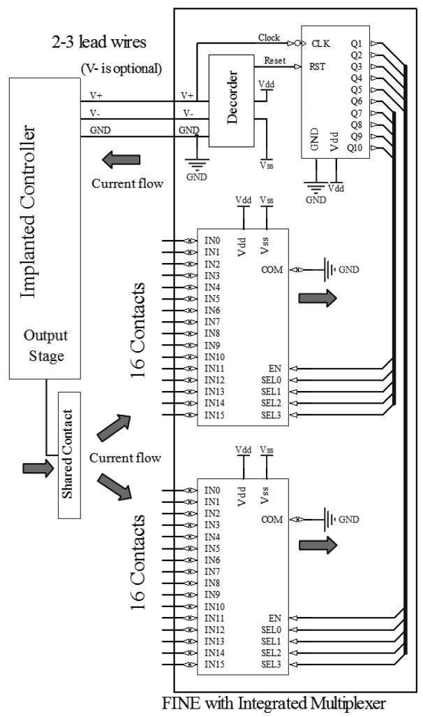
Both designs receive stimulation waveforms and control signals from the implantable controller and consist of 2 analog multiplexers (AMUX), a binary counter, and a decoder (Fig 1). Each of AMUX’s input channels is connected to an electrode contact. Common ports of both AMUXs are connected to the circuit ground. Stimulating current pulses are generated from the implantable controller and passed through a shared contact located outside the electrode. The injected current is passed through an electrode contact and returns to circuit ground. Both AMUXs are configured by the binary counter outputs. Reset and clock for the counter are embedded in the power supply lines and extracted by the decoder. With this architecture, the number of contacts can be increased without increasing the number of lead wires. The decoders for the dual and single-supplied designs are explained in details below.
Fig 1.
Block diagram of the FINE with integrated circuit and the connection to a separate controller. The stimulation current is generated at the implanted controller, passed through the shared contact, an active channel of MUX and returned to GND. For the single supply design, V− is eliminated and Vss is connected to GND, reducing the number of wires to control the thirty-two channel multiplexer to only 2.
1) Dual-supply design
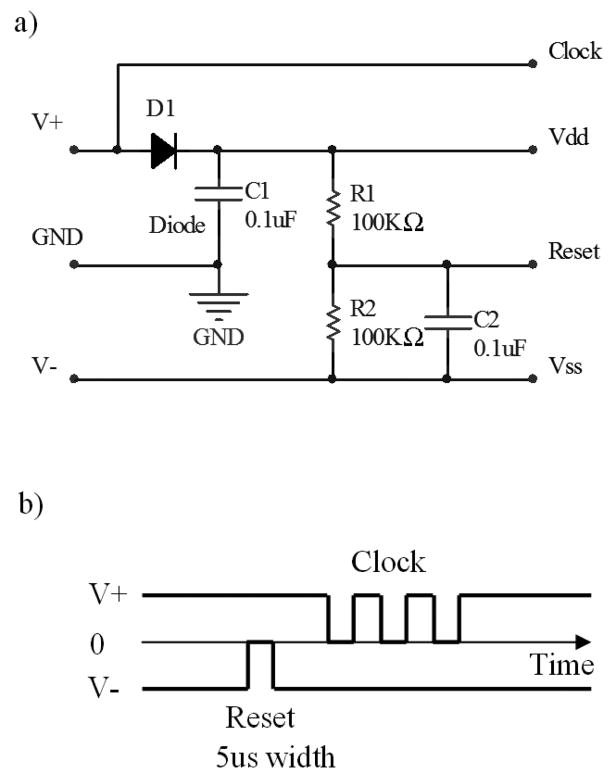
The decoder for the dual-supply design is shown in Fig 2. This design is adapted from a previous study [25]. The decoder consists of 2 resistors, 2 capacitors, and a diode. The design requires 3 interconnecting leads including positive and negative supplies, and circuit ground. Fig 2b shows the decoder which extracts the reset and clock from the supply lines. A reset pulse is produced by temporarily turning off the negative power supply. The clock is then applied to the V+ line to configure the counter and the multiplexers. D1 and C1 rectify and filter the clock signal to produce the positive supply (Vdd) for the counter and multiplexers embedded in the electrode. During channel switching, the stimulating pulse is turned off. Once an active channel of the AMUXs has beens elected, simulating pulses can be applied to the shared contact.
Fig 2.
Decoder and control signal of the dual-supply design. a) Decoder circuit b) Control signal and its timing for configuring the counter: First, the reset pulse is generated by temporarily turning off V−. Then, the clock signal, embedded in V+, is applied. Once an active channel of the multiplexer is configured, the stimulating current can be passed from the shared contact through the active channel in the electrode to GND.
2) Single-supply design
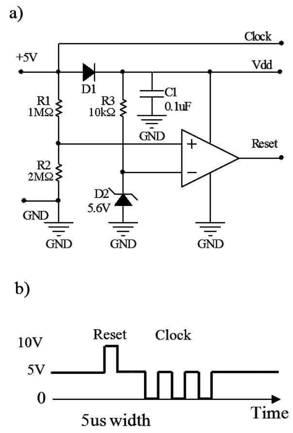
Fig 3 shows the decoder circuit for the single-supply design. The design requires only 2 interconnecting leads; positive supply (V+) and circuit ground. The control signal is shown in Fig 3b. The reset pulse is produced by temporarily applying a 2*V+ pulse into the V+ line. With an appropriate zener voltage of D2 (about 110% V+) and a voltage divider of 66% V+ at VR2, this 2*V+ pulse sets the output of the comparator (TLC3702CP) from zero to 2*V+ and resets the counter. The clock is then applied to the V+ line to configure the multiplexers. D1 and C1 rectify and filter the clock signal to produce a stable positive supply(V dd).
Fig 3.
Decoder and control signal of the single-supply design. a) Decoder circuit b) The control signal and its timing to configure the counter. The reset is initiated by a 2xV+ pulse applied to the V+ line. The clock signal is then followed to configure the counter and multiplexers.
B. Bench – testing set-up
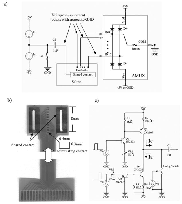
Fig 4 shows a test set-up for measuring the voltage at the analog multiplexer inputs (AMUX) induced by a stimulating current pulse. The AMUX (MAX306) with control circuit was mounted on a protoboard for testing. The AMUX’s COM port was connected to the circuit ground. Each of the AMUX inputs was connected to an individual contact of a passive electrode with the same dimension as the active electrode (Fig 4b). The schematic of the current pulse generator used in this test is shown in Fig 4c. Vc and Va produced 4V pulses to generate cathodic and anodic current pulses, respectively. The analog switch and C1 at the output did not contribute to the stimulating pulse waveform, but were used to prevent any leakage current and to correct any charge imbalance of the pulse. The switch was normally closed and only opened during the pulses. Any imbalanced charge of stimulating pulse would be stored in C1 and discharged when the switch was closed. Stimulating pulses were passed through a shared contact having a much larger surface area than that of stimulating contact (>50 times). The electrode and shared contact were submerged in a saline bath.
Fig 4.
Bench-testing setup a) Test preparation: A passive electrode and shared contact are submerged in a 0.9% saline bath. The electrode is connected to AMUX, and the shared, to the output stage. Stimulation current flows from the shared contact to an active channel of AMUX, and returns to ground. b) A passive electrode used in the test having the same dimension as the active one. c) Output stage producing rectangular biphasic current pulse. C1 and analog switch at the output do not contribute to the stimulating current waveform, but are used for compensating any imbalanced charge of current source by shorting the analog switch between pulses.
C. Electrode Implementation
A flat interface nerve electrode with embedded integrated circuits was implemented with commercially available components. Although both designs were tested, only the dual-supply design was developed. The electrode substrate was made of a three-layer polyimide film (Allflex Inc, USA). Die forms of the sixteen-channel multiplexers (MAX306), binary counter (CD4040), and diode (1N4148) components were employed to reduce the required space. The low crosstalk of the MAX306 (−92dB, Voff/Von) provided isolation between channels. The resistors and capacitors were thick film (0402) surface mount type.
III. Results
A. Bench-testing of the multiplexer and control circuitry
1. Dual-Supply Design
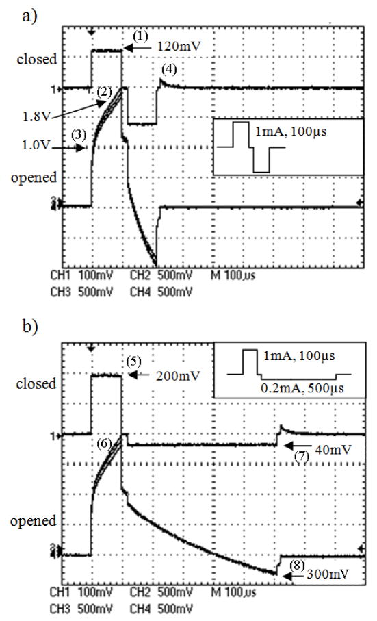
The multiplexing control circuit was tested by generating signals to short one of the 32-channels to ground while leaving the others open. Fig 5a shows the voltage induced by a current-controlled pulse measured at 4 positions: the AMUX’s closed channel connected to a contact on one end, the opened contact adjacent to the closed one, the opened contact on the other end, and the shared contact (Fig 4a). The stimulating current pulse was symmetrically biphasic, charged-balance, and cathodic-first. The pulse amplitude and duration were 1mA and 100μs for both cathodic and anodic phases with a 20μs delay between the two phases. The AMUX was powered by ±5V.
Fig 5.
Voltage at open and closed channels of multiplexer induced by a) a symmetrical biphasic: the pulse amplitude and duration were 1mA and 100us for both cathodic and anodic phases b) an asymmetrical biphasic: the pulse amplitude and duration were 1mA and 100μs for cathodic phase, and 0.2mA and 500μs for anodic phase (see inset). The induced voltage on the closed channel was lower than that of the open one. The negatively-induced voltage by an asymmetrical pulse was low (<300mV), thus allowing the use of single supply multiplexer.
The induced voltage amplitude on the closed channel was about 120mV (1) on both phases (Fig 5a), suggesting that the AMUX’s internal resistance was approximately 120Ω. The induced voltage on other 3 positions (2) was nearly identical (Fig 5a). The one at the shared contact was slightly higher, and the one adjacent to the closed channel was slightly lower. Since the size of the shared contact is much larger than that of stimulating contact, this induced voltage represents primarily the combination of stimulating contact impedance and AMUX’s internal resistance. The 1V at the onset of the pulse (3) came from the combination of the stimulating contact’s access resistance (~900Ω) and the AMUX’s internal resistance (~100Ω). A voltage of 1.8V at the end of the cathodic pulse (2) suggests that the accumulating voltage in the stimulating contact’s capacitive layer is about 0.8V.
At the end of the second phase, the output-stage analog switch was closed thereby inducing a glitch on the closed channel (4). This glitch could be due to the discharge of imbalanced charge from the stimulating pulse stored in the output capacitor (C1 in Fig 4c.).
The induced voltage on all channels (between −1V and 2V) was within the power supply range (±5V) as required for the AMUX to properly function. This stimulating current waveform, however, cannot be used with the single-supply AMUX (+5V) since any negatively-induced voltage will activate the AMUX’s internal protection diodes (D- in Fig 4a) and be clamped to the D-’s forward bias voltage.
2. Single-Supply Design
For the single-supply AMUX, the negative input voltage must be small enough to prevent activation of the internal clamping diode (D- in Fig 4a). Therefore this circuit cannot pass a symmetrical rectangular biphasic waveform. However, it is still possible to apply biphasic current waveforms with this circuit by using a cathodic-first pulse followed by low-amplitude anodic phase. Fig 5b shows the voltage measured at the same 4 positions (Fig 4a) induced by an asymmetrically biphasic, charge-balanced current pulse. The cathodic pulse amplitude and duration were 1mA and 100us, and the anodic pulse was set to 0.2mA and 500us width with a 20us delay added between cathodic and anodic phases. The AMUX was powered by +5V.
During the cathodic phase, the induced voltage amplitude on the closed channel was about 200mV (5), implying that the AMUX’s internal resistance was approximately 200Ω. This resistance increase compared to the dual-supply AMUX is due to the lower power supply. The induced voltage on the other 3 positions (6) was nearly identical, as expected, and represented primarily the stimulating contact impedance (Fig 5b).
During the anodic phase, the induced voltage on the closed channel became negative, approximately −40mV (7). This amplitude is equal to the stimulating amplitude (0.2mA) multiplied by AMUX’s internal resistance (200Ω). However, unlike the symmetrical biphasic pulse, the induced voltage on the open channels remained positive due to the accumulating charge stored in the double-layer capacitor of the stimulating contact. At the end of the charge-balanced pulse, the double-layer capacitor of the contact was fully discharged and the induced voltage became negative, approximately −300mV (8). This amplitude is approximately the stimulating amplitude (0.2mA) multiplied by the stimulating contact impedance (~900 Ω)plus AMUX’ sinternal resistance (~200 Ω).
Although the induced voltage on AMUX inputs became negative at the end of anodic phase (−40mV and −300mV for the close and open channels), this voltage was not large enough to forward bias the internal clamping diode (D-). Therefore, the AMUX can function properly with the single supply and does not require the negative power supply.
B. Implementation of a FINE with embedded electronics
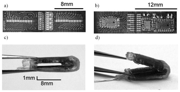
Fig 6 shows a fabricated flat interface nerve electrode with embedded integrated circuit. The electrode substrate was a polyimide film. The electrode contained 32 contacts with a 1mm×8mm opening. This opening size was made slightly larger than a canine hypoglossal nerve [21]. Stimulating contacts and electronic components were located on opposite sides (Fig 6a, b). The contacts were gold plated with a dimension of 300μm ×400μm. The contact separation was 500μm between contact centers (Fig 6a). All components were attached onto the substrate with conductive epoxy (H20E, Epotek) (Fig 6b). The die were wire -bonded and then protected by epoxy (302M, Epotek).
Fig 6.
Implementation of FINE with integrated circuit: a) stimulating contact side b) electronic component side c) finished electrode in closed configuration d) finished electrode in open configuration.
To achieve a tight folding radius of 0.5mm, the substrate was separated into two parts and reconnected with multistrained microwire (AG7/40T, Sigmundcohn, USA) by soldering. This type of wire was also used for the three interconnecting leads. Silicone elastomer (MED−6215, Nusil, USA) was brushed on the entire electrode except for the contact openings. Four 500-μm thick silicone shims were attached to the electrode edges. Once dried, the substrate was folded 180 degree to create a rectangular opening of 1mm×8mm (Fig 6c). Elastomer was re-applied to protect the interconnecting wires between the two substrates. Fig 6d shows the electrode final implementation. This electrode was developed for a feasibility study and not intended for any long term implantation.
The FINE, with embedded integrated circuits, was tested in a saline bath. The shared contact was the same one used in the bench test. The electrode was powered by ±5V. The induced voltage at the current source output was measured when applying a symmetrical biphasic pulse (1mA and 100us). The induced voltage, as expected, was similar to that found at the AMUX open channel shown in Fig 5b and not shown.
IV. Discussion
This study presents a solution to the problem of the large number of wires required in multi-contact nerve electrode. This large number of contacts is necessary to implement both fascicular and subfascicular stimulation selectivity [23]. By embedding multiplexing electronics it is possible to decrease the number of interconnecting leads. The combination of the FINE and integrated circuit shows one distinct advantage. That is, the flat area of the electrode is a suitable location for housing an electronic module, especially for a large nerve such as a femoral nerve that is 12mm wide and <4mm thick [17]. The proposed circuit designs require only 2 and 3 interconnecting leads for the single and dual-supply designs respectively, regardless of the number of contacts.
The decoder module eliminates the lead wires for channel selection, but requires additional circuit area (about 20%) and limits the channel-to-channel switching time. However, a small number of leads is preferred in order to reduce the lead stiffness and prevent nerve damage. The circuitry area and overall electrode size can be decreased by using an application-specific integrated circuit (ASIC). The switching time between channels is also negligible when compared to a typical stimulation pulse interval of about 30msec [26]. Since only a few contacts in the electrode are used during selective stimulation [17, 20], the allowable switching time will be about 5msec. Although a 12-bit counter was used in this study, a 6-bit binary counter is sufficient to select one of the 32 outputs for the two 16-channel multiplexers. The switching time is less than 1msec for a clock frequency of 100k-Hz.
The stimulating waveform for the dual-supply design can be arbitrary as long as the induced voltage at AMUX’s inputs is within the power supply range. An anodic-first pulse could also be used for stimulation if needed and the induced voltage would be the inverse of that shown in Fig 5a. Although the stimulating waveform for the single-supply design is limited to a cathodic-first pulse followed by low-amplitude anodic pulse, this type of stimulating waveform has been used clinically for over a decade with no complications [27, 28].
Power supply level for the AMUXs needs to cover the range of the induced voltage on their inputs. Therefore, the maximum induced voltage on AMUXs needs to be predetermined experimentally by applying the maximum charge and stimulating current amplitude for a specific application. The induced voltage in-vivo is expected to be higher than that obtained in-vitro due to the increase in access resistance.
The two proposed circuit designs do not include any current source in the electrode. The output stage is located in a separate controller and generates the stimulating current through a shared contact. This approach greatly simplifies the electrode’s circuit design without sacrificing any electrode performance. Moreover, arbitrary stimulating waveforms can be used to further enhance the spatial selectiveness of the electrode[29], without modifying the electrode.
The configuration of these two proposed circuit designs is limited to monopolar stimulation. Experiments in peripheral nerve have shown that, as spatial selective stimulation is concerned, monopolar stimulation can achieve the same selectivity level as the tripolar configuration [30]. However, bipolar or tripolar stimulation could also be implemented by including the shared contact in the electrode with the addition of extra interconnecting lead wire. Neither of the two proposed designs can perform current steering that could enhance the spatial selectivity [6]. Preliminary modeling results of the FINE, however, have suggested that the steering stimulation is not required for a high contact density electrode in order to achieve a desired selectivity [17].
Although the electrode substrate was flexible, it was significantly stiffened by the surface-mounted components. Moreover, the 3-layer polyimide film could not be bent easily in order to create a narrow opening (<1mm). The electrode had to be split into upper and lower sections and reconnected by interconnecting wires. A thinner 3-layer flexible substrate might allow bending the substrate and simplify the fabrication. An ASIC implementation of this design would significantly decrease the number of integrated circuits and permit the use of 1-layer thin film, thus restoring flexibility of the electrode substrate.
The design of the electrode with gold plating on a flexible printed circuit board was used for its simplicity and commercial availability. However, electrodeposition of iridium oxide would be required for nerve stimulation to increase the charge injection limit and prevent metal dissolution. [31]
Similarly, this study was not designed to study or resolve the question of hermetic seal and encapsulation. Intensive studies in polymer encapsulation have, however, shown that electronic modules encapsulated in silicone have been successfully implanted in patients for over 20 years [32–37]. Silicone encapsulation for bare-die circuits have been attempted [25]. Encapsulation of the developed electrode for long-term implant has yet to be overcome.
In conclusion, a multichannel flat interface nerve electrode with embedded integrated electronic has been designed and tested. The electrode contains thirty-two stimulating sites and requires only two or three interconnecting leads for the single or dual-supply designs, respectively. The number of contacts can be increased without increasing the interconnecting leads. The stimulating waveform for the dual-supply design can be arbitrary whereas that for the single-supply design is limited to a cathodic-first pulse followed by low-amplitude anodic pulse. This electrode can be applied to a large flat nerve containing several fascicles, such as in femoral nerve stimulation for a standing neuroprosthetic system [17]. A thinner flexible substrate will be used to maintain the electrode flexibility and facilitate the bend in the middle of the electrode. For long-term implantation, liquid crystal polymer (LCP) could be utilized instead of polyamide as an electrode substrate due to its low water absorption rate.
References
- 1.Stein RB, Peckham PH, Popovic DB. Neural Prostheses: Replacing Motor Function After Disease or Disability. New York: Oxford Univ. Press; 1992. [Google Scholar]
- 2.Crago PE, et al. The choice of pulse duration for chronic electrical stimulation via surface, nerve, and intramuscular electrodes. Ann Biomed Eng. 1974;2(3):252–64. doi: 10.1007/BF02368496. [DOI] [PubMed] [Google Scholar]
- 3.Grandjean PA, Mortimer JT. Recruitment properties of monopolar and bipolar epimysial electrodes. Ann Biomed Eng. 1986;14(1):53–66. doi: 10.1007/BF02364648. [DOI] [PubMed] [Google Scholar]
- 4.Caldwell CW, Reswick JB. A percutaneous wire electrode for chronic research use. IEEE Trans Biomed Eng. 1975;22(5):429–32. doi: 10.1109/tbme.1975.324516. [DOI] [PubMed] [Google Scholar]
- 5.Naples GG, et al. A spiral nerve cuff electrode for peripheral nerve stimulation. IEEE Trans Biomed Eng. 1988;35(11):905–16. doi: 10.1109/10.8670. [DOI] [PubMed] [Google Scholar]
- 6.Sweeney JD, Ksienski DA, Mortimer JT. A nerve cuff technique for selective excitation of peripheral nerve trunk regions. IEEE Trans Biomed Eng. 1990;37(7):706–15. doi: 10.1109/10.55681. [DOI] [PubMed] [Google Scholar]
- 7.Veraart C, Grill WM, Mortimer JT. Selective control of muscle activation with a multipolar nerve cuff electrode. IEEE Trans Biomed Eng. 1993;40(7):640–53. doi: 10.1109/10.237694. [DOI] [PubMed] [Google Scholar]
- 8.Branner A, Stein RB, Normann RA. Selective stimulation of cat sciatic nerve using an array of varying-length microelectrodes. J Neurophysiol. 2001;85(4):1585–94. doi: 10.1152/jn.2001.85.4.1585. [DOI] [PubMed] [Google Scholar]
- 9.McDonnall D, Clark GA, Normann RA. Selective motor unit recruitment via intrafascicular multielectrode stimulation. Can J Physiol Pharmacol. 2004;82(8–9):599–609. doi: 10.1139/y04-047. [DOI] [PubMed] [Google Scholar]
- 10.Zheng X, et al. Longitudinally implanted intrafascicular electrodes for stimulating and recording fascicular physioelectrical signals in the sciatic nerve of rabbits. Microsurgery. 2003;23(3):268–73. doi: 10.1002/micr.10116. [DOI] [PubMed] [Google Scholar]
- 11.Lago N, et al. Assessment of biocompatibility of chronically implanted polyimide and platinum intrafascicular electrodes. IEEE Trans Biomed Eng. 2007;54(2):281–90. doi: 10.1109/TBME.2006.886617. [DOI] [PubMed] [Google Scholar]
- 12.McNeal DR, Bowman BR. Selective activation of muscles using peripheral nerve electrodes. Med Biol Eng Comput. 1985;23(3):249–53. doi: 10.1007/BF02446866. [DOI] [PubMed] [Google Scholar]
- 13.Veltink PH, Van Alste JA, Boom HB. Influences of stimulation conditions on recruitment of myelinated nerve fibers: a model study. IEEE Trans Biomed Eng. 1988;35(11):917–24. doi: 10.1109/10.8671. [DOI] [PubMed] [Google Scholar]
- 14.Veltink PH, et al. A modeling study of nerve fascicle stimulation. IEEE Trans Biomed Eng. 1989;36(7):683–92. doi: 10.1109/10.32100. [DOI] [PubMed] [Google Scholar]
- 15.Veltink PH, van Alste JA, Boom HB. Multielectrode intrafascicular and extraneural stimulation. Med Biol Eng Comput. 1989;27(1):19–24. doi: 10.1007/BF02442165. [DOI] [PubMed] [Google Scholar]
- 16.Tyler DJ, Durand DM. Functionally selective peripheral nerve stimulation with a flat interface nerve electrode. IEEE Trans Neural Syst Rehabil Eng. 2002;10(4):294–303. doi: 10.1109/TNSRE.2002.806840. [DOI] [PubMed] [Google Scholar]
- 17.Schiefer MA, Triolo RJ, Tyler DJ. A model of selective activation of the femoral nerve with a flat interface nerve electrode for a lower extremity neuroprosthesis. IEEE Trans Neural Syst Rehabil Eng. 2008;16(2):195–204. doi: 10.1109/TNSRE.2008.918425. [DOI] [PMC free article] [PubMed] [Google Scholar]
- 18.Choi AQ, Cavanaugh JK, Durand DM. Selectivity of multiple-contact nerve cuff electrodes: a simulation analysis. IEEE Trans Biomed Eng. 2001;48(2):165–72. doi: 10.1109/10.909637. [DOI] [PubMed] [Google Scholar]
- 19.Schiefer MA, et al. Modeling selective stimulation with a flat interface nerve electrode for standing neuroprosthetic systems; The 2nd international IEEE EMBS Conference on Neural Engineering; Arlington, Virginia, USA. 2005. [DOI] [PubMed] [Google Scholar]
- 20.Leventhal DK, Durand DM. Subfascicle stimulation selectivity with the flat interface nerve electrode. Ann Biomed Eng. 2003;31(6):643–52. doi: 10.1114/1.1569266. [DOI] [PubMed] [Google Scholar]
- 21.Yoo PB, Sahin M, Durand DM. Selective stimulation of the canine hypoglossal nerve using a multi-contact cuff electrode. Ann Biomed Eng. 2004;32(4):511–9. doi: 10.1023/b:abme.0000019170.74375.fb. [DOI] [PubMed] [Google Scholar]
- 22.Leventhal DK, Durand DM. Chronic measurement of the stimulation selectivity of the flat interface nerve electrode. IEEE Trans Biomed Eng. 2004;51(9):1649–58. doi: 10.1109/TBME.2004.827535. [DOI] [PubMed] [Google Scholar]
- 23.Leventhal DK, Cohen M, Durand DM. Chronic histological effects of the flat interface nerve electrode. J Neural Eng. 2006;3(2):102–13. doi: 10.1088/1741-2560/3/2/004. [DOI] [PubMed] [Google Scholar]
- 24.Najafi K, Wise KD. An implantable multielectrode array with on-chip signal processing. IEEE Journal of Solid-State Circuits. 1986;21(6):1035–1044. [Google Scholar]
- 25.Schuettler M, Koch KP, Stieglitz T, Scholz O, Haberer W, Keller R, Meyer JU. Multichannel neural cuff electrodes with integrated multiplexercircuit; 1st Annual International IEEE-EMBS Special Topic Conference on Microtechnologies in Medicine and Biology, 1st Annual International, Conference; Lyon, France. 2000. pp. 624–629. [Google Scholar]
- 26.Solomonow M. External control of the neuromuscular system. IEEE Trans Biomed Eng. 1984;31(12):752–63. doi: 10.1109/TBME.1984.325235. [DOI] [PubMed] [Google Scholar]
- 27.Smith B, et al. An externally powered, multichannel, implantable stimulator-telemeter for control of paralyzed muscle. IEEE Trans Biomed Eng. 1998;45(4):463–75. doi: 10.1109/10.664202. [DOI] [PubMed] [Google Scholar]
- 28.Wuolle KS, et al. Satisfaction with upper-extremity surgery in individuals with tetraplegia. Arch Phys Med Rehabil. 2003;84(8):1145–9. doi: 10.1016/s0003-9993(03)00292-2. [DOI] [PubMed] [Google Scholar]
- 29.Grill WM, Mortimer JT. Inversion of the current-distance relationship by transient depolarization. IEEE Trans Biomed Eng. 1997;44(1):1–9. doi: 10.1109/10.553708. [DOI] [PubMed] [Google Scholar]
- 30.Tarler MD, Mortimer JT. Comparison of joint torque evoked with monopolar and tripolar-cuff electrodes. IEEE Trans Neural Syst Rehabil Eng. 2003;11(3):227–35. doi: 10.1109/TNSRE.2003.816867. [DOI] [PubMed] [Google Scholar]
- 31.Meyer RD, et al. Electrodeposited iridium oxide for neural stimulation and recording electrodes. IEEE Trans Neural Syst Rehabil Eng. 2001;9(1):2–11. doi: 10.1109/7333.918271. [DOI] [PubMed] [Google Scholar]
- 32.Donaldson PE. Encapsulating microelectronic implants in one-part silicone rubbers. Med Biol Eng Comput. 1989;27(1):93–4. doi: 10.1007/BF02442177. [DOI] [PubMed] [Google Scholar]
- 33.Donaldson PE. Aspects of silicone rubber as an encapsulant for neurological prostheses. Part 1. Osmosis. Med Biol Eng Comput. 1991;29(1):34–9. doi: 10.1007/BF02446293. [DOI] [PubMed] [Google Scholar]
- 34.Donaldson PE, Aylett BJ. Aspects of silicone rubber as encapsulant for neurological prostheses. Part 2: Adhesion to binary oxides. Med Biol Eng Comput. 1995;33(3):289–92. [PubMed] [Google Scholar]
- 35.Donaldson PE. Aspects of silicone rubber as encapsulant for neurological prostheses. Part 3: Adhesion to mixed oxides. Med Biol Eng Comput. 1995;33(5):725–7. doi: 10.1007/BF02510794. [DOI] [PubMed] [Google Scholar]
- 36.Donaldson PE. Aspects of silicone rubber as encapsulant for neurological prostheses. Part 4: Two-part rubbers. Med Biol Eng Comput. 1997;35(3):283–6. doi: 10.1007/BF02530051. [DOI] [PubMed] [Google Scholar]
- 37.Brindley GS. The first 500 sacral anterior root stimulators: implant failures and their repair. Paraplegia. 1995;33(1):5–9. doi: 10.1038/sc.1995.3. [DOI] [PubMed] [Google Scholar]


