Abstract
The capability to image tissue motion such as blood flow through an endoscope could have many applications in medicine. Spectrally encoded endoscopy (SEE) is a recently introduced technique that utilizes a single optical fiber and miniature diffractive optics to obtain endoscopic images through small diameter probes. Using spectral-domain interferometry, SEE is furthermore capable of three-dimensional volume imaging at video rates. Here we show that by measuring relative spectral phases, this technology can additionally measure Doppler shifts. Doppler SEE is demonstrated in flowing Intralipid phantoms and vibrating middle ear ossicles.
1. Introduction
While advances in endoscopic imaging technologies have made diagnostic and interventional procedures less invasive and more efficient, there is a push to both miniaturize the instrumentation and increase the information content that may be obtained during endoscopy. Two examples with concrete clinical applications include the capability to visualize vascular abnormalities in the placenta [1, 2] and monitor vibrations of middle ear bones (ossicles) to better characterize hearing conduction disorders [3, 4].
Valuable information on blood flow can be obtained by utilizing the optical Doppler effect, which causes a wavelength shift of scattered light due to scattering from flowing red blood cells. Laser Doppler has been used to monitor blood flow in the skin and other organs [5, 6]. A related technique, involving the measurement of speckle pattern modulations has also proven to be highly effective for visualizing vasculature [7, 8]. As opposed to laser Doppler and speckle, which provide transverse images of tissue perfusion, Doppler optical coherence tomography (DOCT) [9], previously demonstrated in the skin [10], retina [11], gastrointestinal tract [12, 13] and in small animals [14–16], enables high-resolution, cross-sectional imaging of microcirculatory flow. Even though these techniques have been implemented within larger endoscopes or through their accessory channels [12, 13, 16], none are presently capable of providing three-dimensional Doppler imaging at video rates through ultraminiature (< 1 mm diameter) probes.
Detecting auditory motion is often performed using laser Doppler vibrometry (LDV) [3, 4, 17, 18], an interferometric point measurement technique that can readily be used to determine the vibration amplitudes of the tympanic membrane (the eardrum). In order to measure vibrations of the middle-ear ossicles or inner-ear structures, however, exposure of the middle ear is required due to the large size of the current instrumentation. Also, LDV is generally a point measurement technique: measuring vibrations of an entire two-dimensional area would require an additional beam scanning mechanism, which would increase the instrument’s bulk and complexity. Wide field Doppler imaging could be useful for understanding middle ear function and diagnosing middle ear disorders, where the vibrating ossicles are mechanically complex. In such cases, the direction, phase, amplitude, and frequency response of the vibrations would have spatial variations that would be difficult to measure using single point measurements.
Spectrally encoded endoscopy (SEE) [19], is a recently introduced technique that employs miniature optics and a diffraction grating to allow three-dimensional imaging through submillimeter endoscopic probes [20]. Using spectral domain interferometry [21], SEE is capable of rapid, video-rate imaging, with high sensitivity, below the tissue surface [22]. Since SEE relies on heterodyne detection with high phase stability, it is suitable for performing Doppler measurements at each resolution element within its field of view. In this work, we demonstrate SEE Doppler imaging in three-dimensions.
2. Experimental setup
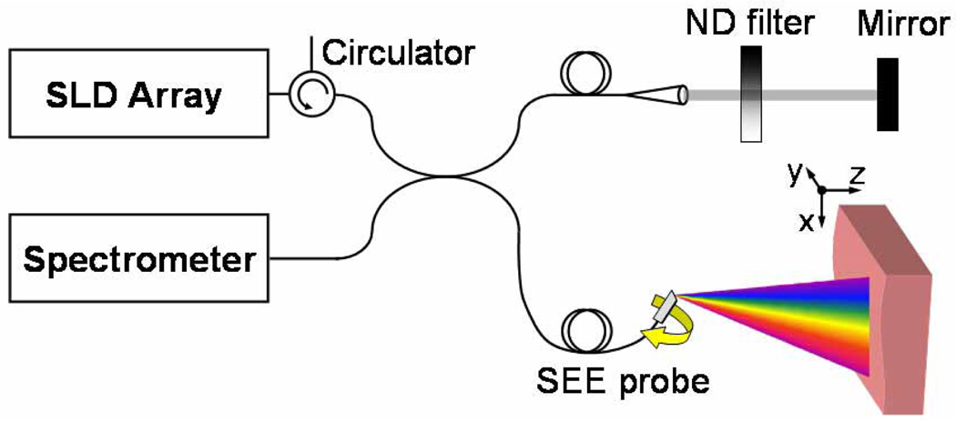
The SEE system has been described in previous work [22]. Briefly, a bench-top system (Fig. 1) was constructed based on a single-mode fiber optic Michelson interferometer. The light source was a super-luminescent diode array (Superlum Diodes Ltd., Q870, center wavelength 870 nm, bandwidth 200 nm), coupled to the 50/50 fiber splitter through a fiber-coupled circulator for isolation (OFR Inc.).
Fig. 1.
Schematic of the spectrally-encoded endoscopy system. ND – neutral density; SEE – spectrally encoded endoscopy.
A miniature endoscopic probe, comprising a 350 µm diameter gradient index lens and a miniature transmission diffraction grating (1000 lines/mm), was used in the sample arm [20]. A galvanometric scanner was used for slow (y) axis scanning of the spectrally encoded line (x axis) by rotating the probe which was mechanically attached to a galvanometer shaft. The reference arm of the interferometer included a mirror on a translation stage and a neutral density filter for controlling the reference power. Spectral interference was detected by a high speed spectrometer that was constructed using a collimator (13 mm beam diameter), a 1200 lines/mm volume phase holographic transmission grating (Wasatch Photonics Inc.), a wide aperture lens (Nikon, f = 85 mm, maximum aperture = 1.8), and a high-speed linear 2048-pixel CCD array (Basler L104k-2k). With a working distance of 13 mm, the resulting field of view was approximately 4.4 ×4.4 × 3.4 mm, with 110 × 110 × 19 resolvable point along the x, y, and z axes, respectively. The total optical power on the sample was approximately 0.8 mW. Detection sensitivity of 95 dB at the center of field of view was measured by calculating the ratio between the maximum detectable intensity and the noise floor, at imaging rate of 30 volumes per second (500 spectra per volume).
To begin, consider a simplified case, wherein the probe beam was not scanned in the y-dimension. After background subtraction, the raw data represented interferometric signal as a function of time (vertical axis) and wavelength (horizontal axis) as depicted in Fig. 2 (left panel). The raw image was then divided into two-dimensional rectangular windows with horizontal and vertical dimensions that corresponded to the spatial resolution of the SEE probe and the required temporal resolution, respectively. In the case of sample motion that was constant over several spectra, Fourier transformation along the vertical axis included frequency peaks that corresponded to the Doppler shift of the signal from the sample, at each horizontal resolution element i. The velocity vi was then calculated according to vi = λi·Δϕi/(2πΔt·cos θ), where Δϕi denoted the phase difference between two adjacent spectra, λi was the corresponding center wavelength, Δt was the time between adjacent line acquisitions, and θ denoted the angle between the SEE beam propagation direction and the direction of sample motion. The maximum detectable axial speed, without phase ambiguity (|Δ ϕi| < π) is given by ṽ=λ/(4·Δt). Generally, the lower limit of measured velocities is limited by the SNR in determining the spectral phase [14], and with no probe scanning along the y-axis, was comparable to other work conducted with Doppler spectral domain OCT [23]. During probe rotation, phase noise increased significantly, setting the measurable minimal velocity to approximately 100 µm/s. An important difference between Doppler SEE and Doppler OCT is that with SEE, the resolution is lower due to spread of the spectrum across the sample [21, 22]. With our current source and spatial resolution, the typical axial resolution of SEE is around 170 μm, which would limit its ability to see the flow within the smallest vessels.
Fig. 2.
Schematic of the data processing for Doppler SEE. STFT – Short time Fourier transformation.
If the sample motion was rapid and periodic, as in the case of acoustic vibrations, the oscillatory frequency was calculated by taking the Fourier transform along the vertical axis. While two line acquisitions were sufficient to detect motion, measuring vibration frequency and amplitude require that the data include at least one oscillation period. According to Nyquist theorem, the maximum frequency that could be measured with this technique is half the camera’s line rate fmin = (2Δt)−1. The lowest frequency limit is equal to the inverse of the total acquisition time. Intensity in the x-z plane was calculated using short-time Fourier transformation along the horizontal axis [21].
In order to accurately capture sample motion over the entire three-dimensional sample we needed to scan the probe along the y axis so that several oscillation periods were acquired for each resolution element along the y-axis. In such case, the minimum image acquisition time was T = Ny / f , where Ny was the number of vertical (y axis) resolution elements in the final image and f denoted the oscillation frequency of the sample. The raw image was divided into two-dimensional rectangular windows that corresponded to the spatial resolution elements of the SEE probe in the x-y plane. Fourier transform was applied to each axis of each window, resulting in three-dimensional reflectance (FT along the horizontal axis) and velocity or frequency (FT along the vertical axis) mapping. Data was captured and stored in real time, and was later processed using Matlab (The Mathworks Inc.).
3. Results
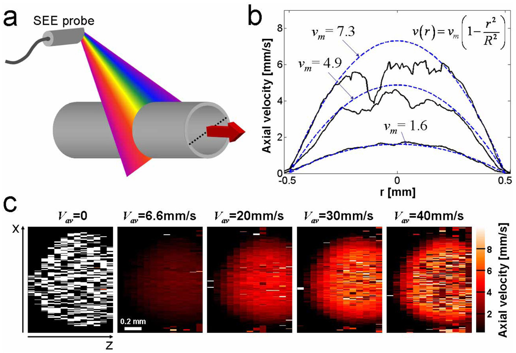
In order to demonstrate the ability of SEE to image and measure flow, we circulated 1% Intralipid through a 1 mm diameter transparent tube [Fig. 3(a)]. Since SEE can image through scattering media,[22] the x-z reflection data, when acquired as a function of time, contained information on the laminar flow of scatterers throughout the entire cross section of the tube. The flow velocity and direction was controlled by a peristaltic pump and its average value was estimated by measuring the total volume that was flowing through the tube as a function of time. At average velocities of 6.6 mm/s and 20 mm/s, the flow was characterized by a parabolic distribution, approaching zero at the tube walls. With a camera line rate of 30 kHz, the maximum detectable axial speed was approximately ṽ ≅ 6 mm/s. The angle between the flow direction and the beam at the central wavelength was θ = ~83°; positive values of the flow velocities indicate flow toward the SEE probe. With an increase in pump speeds (average velocities of 30–40 mm/s), the maximum velocity at the tube’s center was higher than ṽ, resulting in a loss of the velocity signal due to high error rates caused by phase ambiguity. The one-dimensional flow profile along the tube’s diameter [dotted line in Fig. 3(a)] is shown in Fig. 3(b) for different pump flow settings. The solid curves represent the measured velocities extracted from the raw data. Dashed blue lines represent the calculated flow profile for the measured average velocities vav , according to the Navier-Stokes equation: v(r) = vm (1−r2/R2), where vm = 2vav denotes the maximum velocity at the tube’s center, and R = 0.5 mm denotes the tube’s radius. The average velocities measured by SEE, calculated by fitting the measured data to the Navier-Stokes equation (neglecting flow velocities above ṽ), were 6.9, 18.7 and 31.1 mm/s, which are in a good agreement with the predicted average velocities of 6.6, 20 and 30 mm/s, respectively.
Fig. 3.
Intralipid flow by Doppler SEE. (a) Schematic of the single channel flow measurement configuration, showing the SEE probe with respect to the tube and the flow direction (red arrow). (b) Measured (solid curves) and calculated (dashed curves) cross-sectional flow velocities at the tube's center (marked by a dashed line in (a)). (c) Two-dimensional, cross-sectional measurement of the intralipid flow within the tube at different average flow velocities.
Two-dimensional (x-z) distributions of flow velocity across the 1 mm diameter tube are shown in Fig. 3(c) for different flow settings. In the absence of flow, the measured phase fluctuated randomly and no flow was detected (left panel). At average velocities of 6.6 mm/s and 20 mm/s the flow velocity distributions showed two-dimensional parabolic profiles with the highest velocity in the center of the tube. Phase errors around the tube’s center caused loss of Doppler information at higher flow velocities; nevertheless, the flow profile could be estimated by fitting the parabolic curves to regions closer to the tube walls [Fig. 3(b)], where flow was below the maximum measured velocity ṽ.
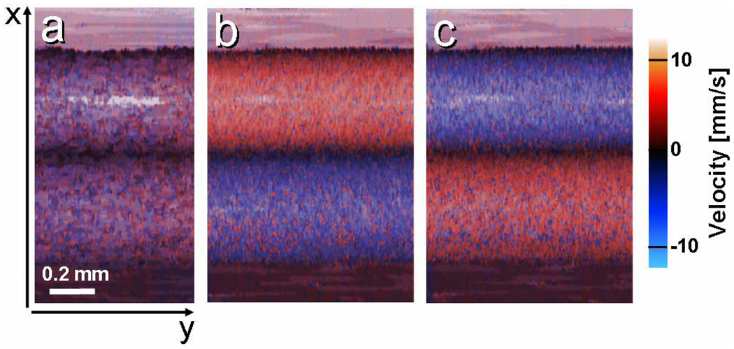
In addition to imaging flow speed and direction, SEE can simultaneously provide reflectance imaging of the tubes and its surroundings. To demonstrate concurrent reflectance and flow imaging, two adjacent, 0.5 mm diameter transparent tubes, with similar but opposite flow directions were imaged at 30 frames per second (30 kHz line rate). In Figs. 4(a)–4(c), the intensity of each pixel represents the total reflectance integrated over depth (z), and the color represents depth-averaged velocity. With no pumping, flow appeared random, resulting in purple hue in both tubes [Fig. 4(a)]. With average flow velocity magnitudes of ~5 mm/s in each tube (estimated by measuring the intralipid volume accumulated per 20 seconds), the two opposite flow directions are clearly noticeable [Figs. 4(b), 4(c)], with red (blue) hues corresponding to flow toward (away from) the SEE probe.
Fig. 4.
Combined flow and average reflectance images of two 0.5 mm diameter tubes with (a) no flow, (b) similar magnitude, but opposite flow velocities, and (c) flow in opposite directions than (b).
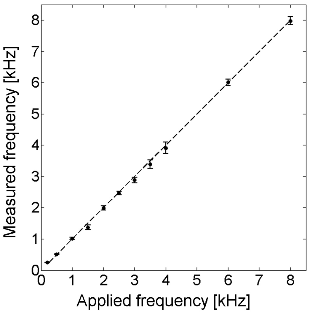
Unlike steady-state flow through a straight tube, which is characterized by relatively linear flow with constant velocity, acoustic vibrations involve oscillatory rapid motions with submicron amplitudes [4, 17]. In order to demonstrate the ability of SEE to accurately measure vibrations at auditory frequencies, we have captured one line (x axis) of a surface of a piezoelectric actuator (Thorlabs Inc., AE0203D08) which was driven by a sinusoidal voltage at different frequencies between 200 Hz and 8 kHz. Vibration amplitudes were kept at ~500 nm throughout the frequency range. The frequencies were calculated from the raw data, which was captured at 30 kHz line rate, and contained 1000 lines per measurement, resulting in a total measurement time of 33.3 ms and a theoretical frequency resolution of 30 Hz (frequency uncertainty is inversely proportional to the time of measurement). The measured frequencies are plotted against the applied frequencies (measured by an oscilloscope) in Fig. 5. The dashed line in Fig. 5 represents the case where the applied frequency equals the measured frequency. The experimental data fits well to the applied frequency (R2 = 0.9993, p < 0.001).
Fig. 5.
Measured vibration frequency by SEE vs. frequency of the sinusoidal voltage waveform applied to the vibration actuator.. Dashed line corresponds to the case where measured frequency equals the applied frequency. Error bars correspond to the standard deviation of the calculated frequency distribution for each wavelength band in the spectrally encoded line (total of 100 measurements).
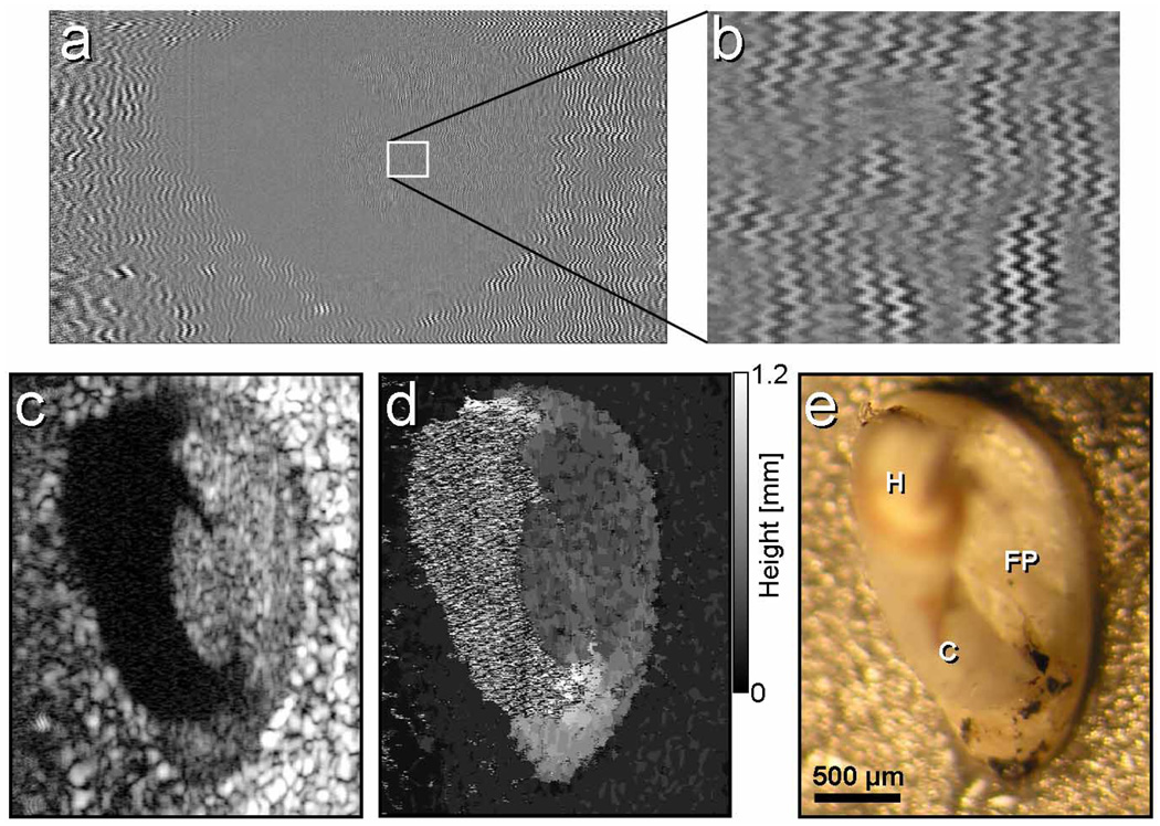
When the spectrally encoded line was scanned across the sample at rates much slower than the acoustic oscillation period, a three-dimensional image was formed, which contained reflectance, height and vibration data for each resolution element. In order to demonstrate the potential of Doppler SEE imaging for measuring vibration of the middle ear ossicles, we attached a human stapes to a closed-loop vibration actuator (1050 Hz, 400 nm p-p amplitude) and imaged the stapes foot-plate at 7.5 kHz line rate with 1200 lines per image. The volume frame rate was therefore 6.25 Hz (Fig. 6). The background-subtracted raw data [Fig. 6(a), zoomed-in region of (a) is shown in Fig. 6(b)] contained an interferometric fringe pattern that revealed the sample vibrations at every point in the image. As expected, the frequency distribution was uniform across the foot-plate and the metallic base, with a dominant frequency component at 1080 kHz (averaged over the entire sample) and an additional frequency component around 100 Hz, possibly caused by the SEE probe vibrations. Twenty-one lines per probe element were captured, resulting in a frequency measurement uncertainty limit of approximately ±180 Hz. Faster camera line rates or slower imaging frame rates can improve measurement accuracy. While the two-dimensional image was dominated by the strong reflection from the rough metallic surface to which the stapes was attached, the characteristic oval shape of the foot plate was clearly evident at the center of the image [Fig. 6(c)]. Anatomical landmarks such as the two crura and the stapes head were 1 to 3 mm closer to the SEE probe and were beyond the depth range of the SEE system, so no interferometric signal was generated from these regions [black regions on Fig. 6(c)]. The depth map is shown in Fig. 6(d), revealing that the metal base and the foot plate were separated by approximately 500 µm. A white light photograph of the stapes and the metal base from a similar viewing angle is shown for reference in Fig. 6(e).
Fig. 6.
Images of vibrating excised human stapes. (a) The raw fringe data. (b) Magnified region of (a), marked by a white rectangle. (c) Reflectance image. (d) Height map where gray levels represent distance from the metal base. (e) A photograph of the stapes, shown for reference. H – stapes head; FP – foot plate; C – the anterior crus.
4. Discussion
In this paper, we have demonstrated real-time acquisition of volume Doppler image data through a 350 µm diameter probe. Intralipid flow through a tube was demonstrated with accurate reconstruction of flow velocities, encompassing the range of physiologic flow for larger vessels. Our upper limit of velocity detection was limited by the line rate of our CCD camera (30 kHz), which could be easily improved by replacing the detector with higher speed devices that now approach 140 kHz. We did not test the Doppler sensitivity at lower limits of flow, primarily because our target applications involve the detection of flow in larger vessels.
Doppler imaging of the stapes required oversampling the lateral (y) dimension by a factor of ~20 in order to map the acoustic frequencies with sufficient resolution. This oversampling resulted in a volume Doppler imaging frame rate of ~6 Hz. Again, use of a higher speed camera would provide the necessary acquisition rate increase to achieve video rate volumetric Doppler imaging. Another limitation of our current experimental settings was the vibrations of the SEE probe itself caused by the friction between the rotating probe and the metallic mount. These vibrations were typically at 10–200 Hz range [see, for example, the additional vibration component in Fig. 6(b)]. This issue will need to be addressed in any future implementations of Doppler SEE. In this work, processing was performed off-line in Matlab. If written on code optimized for modern-day CPU’s, however, the algorithms presented here can in principle be computed more efficiently to enable real-time display of the volumetric Doppler information.
The work presented here will potentially be important for applications where two- and three-dimensional Doppler imaging will contribute greatly to real-time diagnosis and where probe size is directly correlated to the safety of the procedure. One such example is identifying anastomosing placental vessels in twin-twin transfusion syndrome (TTTS) [1, 2]. In TTTS, one twin receives too much of the placental blood supply, and the other too little, resulting in 80–90% mortality and substantial neurological deficits in the survivors [24, 25]. Laser ablation treatment of the offending vessels is curative, but the size of modern instrumentation is too large [26, 27], resulting in a high incidence of premature rupture of membranes [28, 29]. By incorporating high quality two- and three-dimensional imaging and Doppler blood flow mapping, SEE systems could potentially address the problem of discriminating arteries from veins from multiple vantage points, improving the safety of this procedure.
Another application for this device is detecting vibrations in the auditory range, between 100 Hz and 30 kHz to better diagnose hearing impairments such as otosclerosis and other conduction defects. Due to its sub-millimeter dimensions and high flexibility [20], SEE could be inserted into the middle ear through a small incision in the tympanic membrane, such as routinely introduced for the placement of tympanostomy tubes [30, 31]. While inside the middle ear, SEE could not only image the stapes in three dimensions [21], but it could also map the frequency response of the footplate, which provides an indication on the function of the ossicles. This capability could enable more accurate diagnosis of hearing disorders and open up the possibility of monitoring the response to treatment in a minimally-invasive manner. SEE can also image the entire middle ear, providing a map of the full vibrational distribution of the ossicles, which may permit a better understanding of their functional dynamics.
Acknowledgments
This study was funded in part by the Center for Integration of Medicine and Innovative Technology, a National Science Foundation grant (BES-0086709) and the NIH/NIBIB 1R21EB007718-01
Footnotes
OCIS codes: (170.2150) Endoscopic imaging; (170.3340) Laser Doppler velocimetry; (110.1650) Coherence imaging.
References and links
- 1.Galea P, Jain V, Fisk NM. Insights into the pathophysiology of twin-twin transfusion syndrome. Prenat. Diagn. 2005;25:777–785. doi: 10.1002/pd.1264. [DOI] [PubMed] [Google Scholar]
- 2.Harkness UF, Crombleholme TM. Twin-Twin Transfusion Syndrome: Where do we go from here? Semin. Perinatol. 2005;29:296–304. doi: 10.1053/j.semperi.2005.10.001. [DOI] [PubMed] [Google Scholar]
- 3.Huber AM, Schwab C, Linder T, Stoeckli SJ, Ferrazzini M, Dillier N, Fisch U. Evaluation of eardrum laser Doppler interferometry as a diagnostic tool. Laryngoscope. 2001;111:501–507. doi: 10.1097/00005537-200103000-00022. [DOI] [PubMed] [Google Scholar]
- 4.Rosowski JJ, Nakajima HH, Merchant SN. Clinical utility of laser-Doppler vibrometer measurements in live normal and pathologic human ears. Ear Hear. 2008;29:3–19. doi: 10.1097/AUD.0b013e31815d63a5. [DOI] [PMC free article] [PubMed] [Google Scholar]
- 5.Humeau A, Steenbergen W, Nilsson H, Stromberg T. Laser Doppler perfusion monitoring and imaging: novel approaches. Med. Biol. Eng. Comput. 2007;45:421–435. doi: 10.1007/s11517-007-0170-5. [DOI] [PubMed] [Google Scholar]
- 6.Wardell K, Jakobsson A, Nilsson GE. Laser-Doppler perfusion imaging by dynamic light-scattering. IEEE Trans. Biomed. Eng. 1993;40:309–319. doi: 10.1109/10.222322. [DOI] [PubMed] [Google Scholar]
- 7.Dunn AK, Bolay T, Moskowitz MA, Boas DA. Dynamic imaging of cerebral blood flow using laser speckle. J. Cereb. Blood Flow Metab. 2001;21:195–201. doi: 10.1097/00004647-200103000-00002. [DOI] [PubMed] [Google Scholar]
- 8.Briers JD. Laser Doppler, speckle and related techniques for blood perfusion mapping and imaging. Physiol. Meas. 2001;22:R35–R66. doi: 10.1088/0967-3334/22/4/201. [DOI] [PubMed] [Google Scholar]
- 9.Yang VXD, Gordon ML, Qi B, Pekar J, Lo S, Seng-Yue E, Mok A, Wilson BC, Vitkin IA. High speed, wide velocity dynamic range Doppler optical coherence tomography (Part I): System design, signal processing, and performance. Opt. Express. 2003;11:794–809. doi: 10.1364/oe.11.000794. [DOI] [PubMed] [Google Scholar]
- 10.Zhao YH, Chen ZP, Saxer C, Xiang SH, de Boer JF, Nelson JS. Phase-resolved optical coherence tomography and optical Doppler tomography for imaging blood flow in human skin with fast scanning speed and high velocity sensitivity. Opt. Lett. 2000;25:114–116. doi: 10.1364/ol.25.000114. [DOI] [PubMed] [Google Scholar]
- 11.White BR, Pierce MC, Nassif N, Cense B, Park BH, Tearney GJ, Bouma BE, Chen TC, de Boer JF. In vivo dynamic human retinal blood flow imaging using ultra-high-speed spectral domain optical Doppler tomography. Opt. Express. 2003;11:3490–3497. doi: 10.1364/oe.11.003490. [DOI] [PubMed] [Google Scholar]
- 12.Yang VXD, Tang SJ, Gordon ML, Qi B, Gardiner GR, Cirocco M, Kortan P, Haber GB, Kandel G, Vitkin IA, Wilson BC, Marcon NE. Endoscopic Doppler optical coherence tomography in the human GI tract: initial experience. Gastrointest. Endosc. 2005;61:879–890. doi: 10.1016/s0016-5107(05)00323-8. [DOI] [PubMed] [Google Scholar]
- 13.Vakoc BJ, Shishko M, Yun SH, Oh WY, Suter MJ, Desjardins AE, Evans JA, Nishioka NS, Tearney GJ, Bouma BE. Comprehensive esophageal microscopy by using optical frequency-domain imaging (with video) Gastrointest. Endosc. 2007;65:898–905. doi: 10.1016/j.gie.2006.08.009. [DOI] [PMC free article] [PubMed] [Google Scholar]
- 14.Westphal V, Yazdanfar S, Rollins AM, Izatt JA. Real-time, high velocity-resolution color Doppler optical coherence tomography. Opt. Lett. 2002;27:34–36. doi: 10.1364/ol.27.000034. [DOI] [PubMed] [Google Scholar]
- 15.Mariampillai A, Standish BA, Munce NR, Randall C, Liu G, Jiang JY, Cable AE, Vitkin IA, Yang VXD. Doppler optical cardiogram gated 2D color flow imaging at 1000 fps and 4D in vivo visualization of embryonic heart at 45 fps on a swept source OCT system. Opt. Express. 2007;15:1627–1638. doi: 10.1364/oe.15.001627. [DOI] [PubMed] [Google Scholar]
- 16.Yang VXD, Mao YX, Munce N, Standish B, Kucharczyk W, Marcon NE, Wilson BC, Vitkin IA. Interstitial Doppler optical coherence tomography. Opt. Lett. 2005;30:1791–1793. doi: 10.1364/ol.30.001791. [DOI] [PubMed] [Google Scholar]
- 17.Nuttall AL, Dolan DF, Avinash G. Laser Doppler velocimetry of basilar-membrane vibration. Hear. Res. 1991;51:203–213. doi: 10.1016/0378-5955(91)90037-a. [DOI] [PubMed] [Google Scholar]
- 18.Rosowski JJ, Mehta RP, Merchant SN. Diagnostic utility of laser-Doppler vibrometry in conductive hearing loss with normal tympanic membrane. Otol. Neurot. 2003;24:165–175. doi: 10.1097/00129492-200303000-00008. [DOI] [PMC free article] [PubMed] [Google Scholar]
- 19.Tearney GJ, Webb RH, Bouma BE. Spectrally encoded confocal microscopy. Opt. Lett. 1998;23:1152–1154. doi: 10.1364/ol.23.001152. [DOI] [PubMed] [Google Scholar]
- 20.Yelin D, Rizvi I, White WM, Motz JT, Hasan T, Bouma BE, Tearney GJ. Three-dimensional miniature endoscopy. Nature. 2006;443:765–765. doi: 10.1038/443765a. [DOI] [PubMed] [Google Scholar]
- 21.Yelin D, White WM, Motz JT, Yun SH, Bouma BE, Tearney GJ. Spectral-domain spectrally-encoded endoscopy. Opt. Express. 2007;15:2432–2444. doi: 10.1364/oe.15.002432. [DOI] [PubMed] [Google Scholar]
- 22.Yelin D, Bouma BE, Tearney GJ. Volumetric sub-surface imaging using spectrally encoded endoscopy. Opt. Express. 2007;16:1748–1757. doi: 10.1364/oe.16.001748. [DOI] [PubMed] [Google Scholar]
- 23.Wang YM, Bower BA, Izatt JA, Tan O, Huang D. In vivo total retinal blood flow measurement by Fourier domain Doppler optical coherence tomography. J. Biomed. Opt. 2007;12 doi: 10.1117/1.2772871. [DOI] [PubMed] [Google Scholar]
- 24.Gray PH, Cincotta RB, Phythian G. Long term outcome of twin to twin transfusion ('stuck twin') syndrome. Pediatric Research. 1999;45:244A–244A. [Google Scholar]
- 25.Lewi L, Van Schoubroeck D, Gratacos E, Witters I, Timmerman D, Deprest J. Monochorionic diamniotic twins: complications and management options. Curr. Opin. Obstet. Gynecol. 2003;15:177–194. doi: 10.1097/00001703-200304000-00013. [DOI] [PubMed] [Google Scholar]
- 26.Bussey JG, Luks F, Carr SR, Plevyak M, Tracy TF. Minimal-access fetal surgery for twin-to-twin transfusion syndrome. Surg. Endosc. and other Interventional Techniques. 2004;18:83–86. doi: 10.1007/s00464-003-8179-9. [DOI] [PubMed] [Google Scholar]
- 27.Deprest JA, Lerut TE, Vandenberghe K. Operative fetoscopy: New perspective in fetal therapy? Prenat. Diagn. 1997;17:1247–1260. [PubMed] [Google Scholar]
- 28.Hecher K, Plath H, Bregenzer T, Hansmann M, Hackeloer BJ. Endoscopic laser surgery versus serial amniocenteses in the treatment of severe twin-twin transfusion syndrome. Am. J. Obstet. Gynecol. 1999;180:717–724. doi: 10.1016/s0002-9378(99)70278-4. [DOI] [PubMed] [Google Scholar]
- 29.Ville Y, Hecher K, Gagnon A, Sebire N, Hyett J, Nicolaides K. Endoscopic laser coagulation in the management of severe twin-to-twin transfusion syndrome. B. J. Obstet. Gynaecol. 1998;105:446–453. doi: 10.1111/j.1471-0528.1998.tb10132.x. [DOI] [PubMed] [Google Scholar]
- 30.Knutsson J, von Unge M. Five-year results for use of single-flanged tympanostomy tubes in children. J. Laryngol. Otol. Forthcoming. 2007:1–6. doi: 10.1017/S0022215107009942. [DOI] [PubMed] [Google Scholar]
- 31.Tavin ME, Gordon M, Ruben RJ. Hearing results with the use of different tympanostomy tubes - a prospective study. Int. J. Pediatr. Otorhinolaryngol. 1988;15:39–50. doi: 10.1016/0165-5876(88)90049-3. [DOI] [PubMed] [Google Scholar]


