Abstract
Particulate aluminum films of varied thicknesses were deposited on quartz substrates by thermal evaporation. These nanostructured substrates were characterized by scanning electron microscopy (SEM). With the increase of aluminum thickness, the films progress from particulate toward smooth surfaces as observed by SEM images. To date, metal-enhanced fluorescence (MEF) has primarily been observed in the visible–NIR wavelength region using silver or gold island films or roughened surfaces. We now show that fluorescence could also be enhanced in the ultraviolet-blue region of the spectrum using nanostructured aluminum films. Two probes, one in the ultraviolet and another one in the blue spectral region, have been chosen for the present study. We observed increased emission, decrease in fluorescence lifetime, and increase in photostability of a DNA base analogue 2-aminopurine and a coumarin derivative (7-HC) in 10-nm spin-casted poly(vinyl alcohol) film on Al nanostructured surfaces. The fluorescence enhancement factor depends on the thickness of the Al films as the size of the nanostructures formed varies with Al thickness. Both probes showed increased photostability near aluminum nanostructured substrates, which is consistent with the shorter lifetime. Our preliminary studies indicate that Al nanostructured substrates can potentially find widespread use in MEF applications particularly in the UV-blue spectral regime. Furthermore, these Al nanostructured substrates are very stable in buffers that contain chloride salts compared to usual silver colloid-based substrates for MEF, thus furthering the usefulness of these Al-based substrates in many biological assays where high concentration of salts are required. Finite-Difference Time-Domain calculations were also employed to study the enhanced near-fields induced around aluminum nanoparticles by a radiating fluorophore, and the effect of such enhanced fields on the fluorescence enhancement observed was discussed.
Fluorescence detection presently is a central technology in biological research and medical diagnostics. While fluorescence is a sensitive method, there is a continuing need for increased sensitivity, as evidenced by the use of amplification methods such as ELISA1,2 and PCR.3,4 However, the detection and sensitivity in general is limited by the fluorescence quantum yield and photostability of the probe and additionally autofluorescence from the sample. During the past 5 years, there has been a growing interest in the use of colloidal metal particles or roughened metal surfaces for enhanced fluorescence,5–11 in particular silver colloids and silver island films (SIFs). In recent years we have reported on the favorable effects of silver nanoparticles deposited randomly on glass substrates (primarily in the form of SIFs) for increasing the emission intensities (quantum yields), reducing fluorescence lifetimes and increasing the photostability of fluorophores with visible excitation and emission wavelengths. A large number of reports have demostrated that fluorescence intensities can be increased 10-fold or more when the fluorophores are in proximity to the silver particles.8,11,12 The mechanism of this enhancement is, at least in part, due to an increased rate of radiative decay near the particles. Fluorophores in the excited state undergo near-field interactions with the metal particles to create plasmons. While the mechanism of metal-enhanced fluorescence (MEF) is not completely understood, an important factor is the ability of the plasmons to radiate away from the particle.12 Given the electromagnetic nature of this interaction, rather than a chemical interaction, it is reasonable to question whether aluminum can cause MEF.
The remarkable optical characteristics of metallic nanostructures/particles observed of varying sizes, encompassing the visible range, have been investigated by various far-field optical spectroscopy techniques as well as near-field imaging spectroscopy.13–17 When considering aluminum for MEF, it was reported that aluminum quenches fluorescence.18 However, it has been shown that excited fluorophores over smooth aluminum film could create surface plasmons, which eventually radiate into the substrate.19 The spectral properties of the radiation were found to be essentially identical to those of the fluorophore, except for a highly p-polarized emission. The angular dependence of the radiation, as well as the p-polarization, are consistent with radiating surface plasmon. According to the radiating plasmons model for MEF, the scattering component of metal particle extinction contributes to MEF and the absorption component contributes to quenching. So far, MEF has primarily been reported for silver and gold surfaces. This choice of metals restricts the selection of fluorophores to those absorbing and emitting at visible or longer wavelengths. However, many widely used fluorophores absorb or emit at ultraviolet wavelengths. In this regard, aluminum nanostructured substrates can potentially find widespread use in MEF applications particularly in the UV-blue spectral regime. Aluminum is also less expensive than gold or silver. Moreover, aluminum nanostructured substrates are very stable in buffers that contain chloride salts compared to the usual silver colloid-based substrates for MEF, thus furthering the usefulness of these aluminum-based substrates in many biological assays where high concentration of salts are required.
In this report, we describe studies of the MEF displayed by fluorophores in proximity to particulate aluminum films. These particulate Al surfaces were obtained by thermal evaporation followed by depositing a layer of SiO2. The silica layer was used as a spacer layer to avoid direct contact of the fluorophore with the aluminum surfaces. It is reported that the extent of MEF depends on the size of the particles and the distance between the metal and the fluorophore.5,11,12 Accordingly, we investigated the variation in the size of the aluminum nanostructures to identify the optimum conditions for MEF in the ultraviolet and blue spectral region. We also used numerical calculations in the form of the finite-difference time-domain (FDTD) technique to understand our experimental results. FDTD is an implementation of Maxwell's time-dependent curl equations for solving the temporal variation of electromagnetic waves within a finite space that contains a target of arbitrary shape and has recently become the state-of-the-art method for solving Maxwell's equations for complex geometries.20–26 A major advantage of FDTD is that it is a direct time and space solution and, hence, offers the user a unique insight into a myriad of problems in photonics. More information on the FDTD technique can be found in refs 20–26. Our calculations reveal that fluorophores in the near-field of an aluminum nanoparticle induce enhancements of the near-fields around the particle, which we believe play a role in our observation of MEF from aluminum surfaces.
Materials and Methods
Aluminum slugs, silicon monoxide, and 2-aminopurine (2-AP) were purchased from Sigma-Aldrich and used as received. 7-Hy-droxycoumarin-3-carboxylic acid, succinimidyl ester (7-HC) was obtained from Invitrogen Molecular Probes. Chemical structures of 2-AP and 7-HC are shown in Figure 1. Distilled water (with a resistivity of 18.2 MΩ ·cm) purified using the Millipore Milli-Q gradient system was used for sample preparation. Aluminum was deposited on quartz slides using an Edwards Auto 306 vacuum evaporation chamber under high vacuum (<5 × 10⁻⁷ Torr). In each case, the metal deposition step was followed by the deposition of 5 nm of silica via evaporation without breaking vacuum. This step served to protect the metal surface as well as adding a spacer layer between the metal surface and fluorophore. The deposition rate was adjusted by the filament current, and the thickness of film was measured with a quartz crystal microbalance. Fluorophores were deposited on the surface of the substrate by spin coating (Specialty Coating System Inc., Speedline Technologies) 0.25 wt % aqueous solution of low molecular weight poly-(vinyl alcohol) (PVA, MW 13 000–23 000; Aldrich) at 3000 rpm. This composition of PVA forms a ∼10-nm-thick film.
Figure 1.
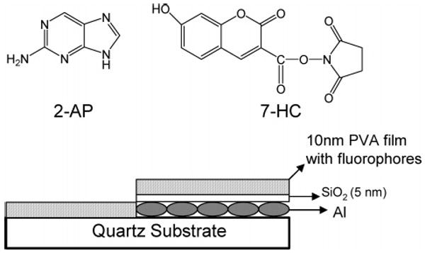
Chemical structures of the probes (a) 2-AP (b) 7-HC. Schematic of the sample geometry.
Absorption spectra were collected using a Hewlett-Packard 8453 spectrophotometer. Fluorescence spectra of probes on solid substrates were recorded using a Varian Cary Eclipse fluorescence spectrophotometer. Both the steady-state and time-domain lifetime measurements were carried out using front face illumination. Time-domain lifetime measurements were obtained on a Pico-Quant lifetime fluorescence spectrophotometer (Fluotime 100). The excitation source was a pulsed laser diode (PicoQuant PDL800-B) with a 20-MHz repetition rate. The instrument response function (IRF) is ∼60 ps. The excitation wavelengths are 285 and 405 nm for 2-AP and 7-HC, respectively. Intensity decays were measured through band-pass interference filters. Emission lifetimes were measured with vertically polarized excitation. Magic angle observation was used in the emission path for the time-domain measurements. This optical configuration reduced scattered light of the excitation wavelength without significant distortion of the spectra or lifetimes.
A portion of the sample was cut and mounted on an Al stub with conductive tape and then observed in an Hitachi SU-70 scanning electron microscope (SEM) directly, i.e., without any further treatment of the sample. Due to the nonconductive substrate (SiO2), ultralow voltage was employed for high-resolution shallow surface observation and imaging using beam deceleration technology. Samples were surveyed at low magnifications to see the general features and the homogeneity. Representative areas were selected for higher magnification investigation.
FDTD calculations were performed using the program FDTD Solutions (Version 5.0) purchased from Lumerical Solutions, Inc., (Vancouver, Canada). The calculations were performed with the parallel FDTD option on a Dell Precision PWS690 workstation with the following components: Dual Quad-Core Intel Xeon E5320 processors at 1.86 GHz, and 8 GB RAM. All postprocessing of FDTD data was performed using MATLAB (version 7.0) purchased from Mathworks (Natick, MA). A time-windowed dipole source, radiating at a fixed wavelength of 375 nm, was used to mimic the emission of 2-AP. This is a soft source, to allow backscattered radiation to pass through it.25 All of the calculations were done by assuming a background refractive index of 1.0. The auxiliary differential equations method20 was used to implement a realistic, frequency-dependent and lossy dielectric model for the aluminum nanoparticle. In order to maintain the accuracy and stability of the FDTD calculations, the smallest grid size to accurately model the prescribed system without being computationally prohibitive was obtained in an iterative fashion (convergence testing). In our implementation of FDTD, convergence testing was done by starting the first calculation with a grid size of λ0/20, where λ0 is the smallest wavelength expected in the simulation, and then reducing the grid size by half in sequential simulations and comparing the results of the calculations. Reduction of the grid size was ceased when a grid size (Δ) was approached where results closely match with the set of results that are obtained from half that particular grid size (Δ/2).25 After testing for convergence, we used a grid size of 2.5 nm for our calculations. The numerical implementation of Maxwell's equations in the FDTD algorithm requires that the time increment Δt have a specific bound relative to the spatial discretization Δ (as mentioned above) to ensure the stability of the time stepping algorithm. In FDTD Solutions, the time step of the simulation is determined by the values of the spatial grid to ensure numerical stability and the user has the flexibility to set the total time of the simulation in femtoseconds.26 Our typical simulations were ranged around 400 fs. This leads to all of our simulations having an excess of 85 000 time steps. Our FDTD software has frequency-domain monitors that perform discrete Fourier transforms of the time-domain fields while the simulation is running. In this manner, continuous wave (CW) information is obtained at any prespecified wavelengths for the various field components (Ex, Ey, Ez, Hx, Hy, Hz). Additionally, the time-domain monitors can provide time-domain information for the various field components within the FDTD simulation region over the entire course of the simulation. At the end of the simulation, the various field components are checked to see if they decay to zero, thus indicating that the simulation has run for a sufficiently long time for the CW information obtained by Fourier transformations to be valid.26
Results and Discussion
Surface roughness is known to provide a pathway for the coupling of incident light (plane waves) to surface plasmons and the creation of far-field radiation from plasmons.28 For this reason, we used a slow deposition rate to result in a rough metal surface. The surface morphology was controlled principally by the film thickness from 2 to 80 nm. The change of surface morphology with the thickness of Al film was characterized by SEM. A 2-nm film was found to be composed of individual particles as shown in Figure 2a. With an increasing thickness of the metal film, it was shown that the particle size became larger. If the Al film was further increased to 40 or 80 nm, the metal film became more and more continuous as observed in Figures 2d and e.
Figure 2.
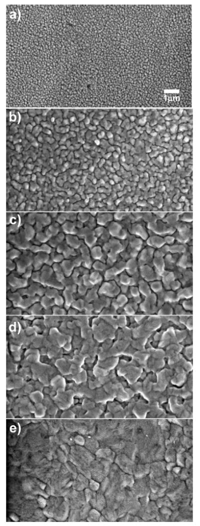
SEM images of (a) 2-, (b) 5-, (c) 10-, (d) 20-, and (e) 80-nm-thick thermally evaporated Al films on quartz substrates.
A very thin Al film with thickness of 2 nm did not display a clear plasmon absorbance band in the UV–visible (200–800 nm) spectral range (Figure 3). The absorbance (optical density) of the Al film was increased with increase of thicknesses of Al; however, no clear plasmon absorbance bands were observed in any of the evaporated aluminum samples. The size of the particles increased with the thickness of Al film as observed by SEM images. When the film thickness was over 20 nm, the metal film became continuous without the presence of individual particles.
Figure 3.
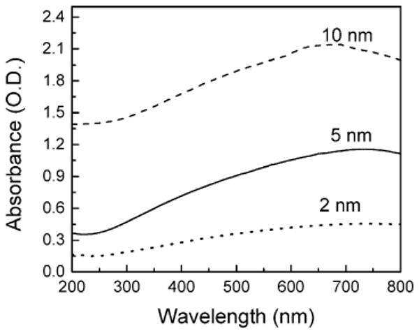
Absorption spectra of 2-, 5-, and 10-nm-thick aluminum films deposited on quartz
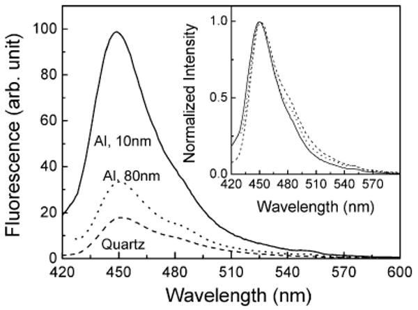
Figure 4 shows the emission spectra of spin coated 10-nm PVA film containing 2-AP on 10- and 80-nm-thick aluminum films and quartz substrates. We found a significant change in the fluorescence intensity when the fluorophores are in proximity to the particulate Al surface. The emission spectra of 2-AP, which are collected through a 320-nm long-pass filter, shows a ∼9-fold greater fluorescence intensity from the 10-nm-thick particulate aluminum films compared to the control (quartz substrate in the present case). A 4-fold enhanced emission was noticed for 80-nm-thick aluminum film compared to a quartz control. The enhancement factor is the ratio of the integrated fluorescence intensity of 2-AP in the 325–500-nm spectral region observed on the aluminum nanostructured and control quartz surfaces. This increase in emission intensity of 2-AP is similar to our reports on the MEF phenomenon primarily observed on the silver island film substrates.10–12 The inset of Figure 4 shows the normalized emission spectra confirming that the emission spectral properties of the probe, 2-AP, are preserved on both metallic nanostructured and quartz substrates.
Figure 4.
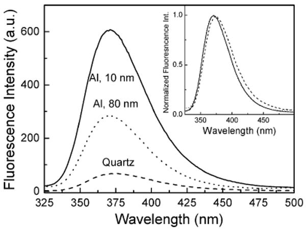
Fluorescence spectra of spin-coated 10-nm PVA film containing 2-AP on 10- and 80-nm-thick aluminum films and quartz. Inset shows the normalized spectra.
The emission spectra of 10-nm PVA film containing 7-HC on quartz and 10- and 80-nm-thick aluminum films are shown in Figure 5. The intensity of 7-HC is increased approximately 6- and 2-fold on 10- and 80-nm aluminum films, respectively, as compared with the control quartz substrate. The inset of Figure 5 shows the normalized emission spectra of 7-HC on quartz and aluminum particulate substrates. The emission spectral features are similar on both quartz and aluminum substrates except for the difference in intensity, suggesting that the emission spectral properties of 7-HC are maintained on metal nanostructured substrates.
Figure 5.
Fluorescence spectra of spin-coated 10-nm PVA film containing 7-HC on 10- and 80-nm-thick aluminum films and quartz slide. Inset shows the normalized spectra.
Figure 6a and b presents the dependence of fluorescence enhancement factor of PVA film containing 2-AP and 7-HC with the thicknesses of deposited aluminum films. In both of the fluorophores, the highest enhancement was observed when the fluorophores are on 10-nm-thick aluminum films. For 2-AP, the enhancement was about only 1.5-fold on 2-nm-thick aluminum films. This could be due to the highly particulate nature of the 2-nm-thick Al film, there still remains a large area of uncoated quartz, and a major portion of the 2-AP is still on the quartz surface. The enhancement factor for 2-AP is consistently around 4-fold for films of 20-nm Al thickness or more. However for 7-HC, the enhancement factor is decreasing monotonically above 10-nm-thick aluminum film.
Figure 6.
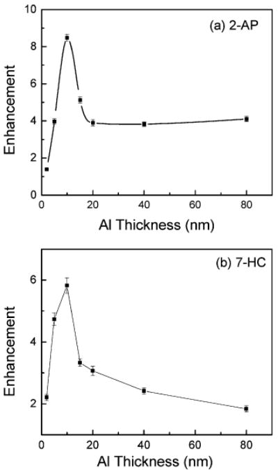
Dependence of fluorescence intensity enhancement factor of (a) 2-AP and (b) 7-HC on the varied thicknesses of aluminum films.
We believe that this enhanced fluorescence observed from the probes on particulate aluminum films cannot be attributed simply to conventional far-field reflection. Reflection occurs when the “metal” is extended over several wavelengths in size. In the present case, the deposited aluminum particles are smaller than or on the order of the wavelength of light, so these aluminum surfaces essentially behave like particles. Hence, in this case, the fluorophore polarizes the particle and the induced dipole radiates coherently with the fluorophore's dipole. Another important point to note is that, in the present case, the fluorophores are approximately within 5–15 nm away from the metal surface, i.e., essentially in the near-field of metal. In this system, it is thought that the excited-state molecule couples to the plasmons on the surface of the aluminum and the combined excited fluorophore–metal complex acts as a unified system, which then radiates. We believe that the observed emission occurs from this near-field metal–fluorophore complex. It is also interesting to note that the extinction spectra of the Al-coated slides shown in Figure 3 do not show a distinct plasmon resonance for the Al-coated films. However, our fluorescence measurements show consistent enhancements with these films. This is another indication that it is the near-field interaction between the excited-state molecule with the surface plasmons of the Al particles that causes the observed enhancement. The plasmon resonances, which manifest as distinct peaks in the extinction spectra, are essentially far-field quantities that do not occur for the evaporated Al samples, and thus, there is no spectral overlap with the absorbance and emission spectra of 2-AP and 7-HC.
We also examined using FDTD, the electromagnetic near-field distributions around an aluminum particle in the near-field of an excited fluorophore. Figure 7a is a schematic illustration of the system studied. A spherical, aluminum nanoparticle with a diameter of 500 nm is placed at the origin. The SEM images of the 10-nm-thick aluminum film in Figure 2c (which gave the maximum enhancements) revealed average particle sizes of ∼500 nm, and hence, we choose this dimension for our calculations. We are aware that the morphology of the actual particles is not exactly spherical, but we choose to use the simplest shape for our calculations. The main objective of the calculations is to investigate whether an excited fluorophore in the near-field of an aluminum nanoparticle can cause field enhancements around the particle. We believe that any near-field enhancements induced by a fluorophore around the aluminum nanoparticle plays a significant role in creating the MEF that we observe experimentally. In our calculations, the fluorophore is placed 10 nm from the surface of the aluminum along the negative x-axis. It is assumed the excitation stage of fluorescence has occurred and the fluorophore is now emitting radiation. We model this radiating fluorophore as an oscillating, point dipole. The fluorophore is oriented with its dipole moment along the x-axis, which is normal to the metal surface. Figure 7b shows the electric field intensity in the x–y plane around the 500-nm aluminum nanoparticle separated 10 nm from the fluorophore (oriented along the x-axis). For comparison, Figure 7c shows the intensity around an isolated fluorophore (or oscillating dipole). We have verified, as might be expected, that this latter intensity is similar to the near-field of a Hertz dipole.28 Figure 7d is an image of the near-field enhancement that is generated by dividing the intensity around the fluorophore-nanoparticle complex by the intensity around the isolated fluorophore. All the images are displayed in the logarithmic scale (base 10) for clarity of presentation. The color scale for Figure 7d has been set from 0 to 1.1 to focus on regions that show enhancement. The areas in Figure 7d that are dark red and correspond in the color map to values greater than one are areas where we see maximum enhancements in the near-field around the aluminum particle. It is interesting to observe that the near-field is not enhanced between the particle and the dipole, but is distributed around the nanoparticle with the maximum enhancements on the side of the nanoparticle distal to the fluorophore. Such spatial variations in the near-field enhancements are not easily inferred from experimental observations and thus provide additional insight into the nature of metal-enhanced fluorescence.
Figure 7.
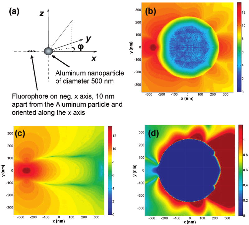
(a) Schematic diagram of the model radiating fluorophore/metal nanoparticle system studied using FDTD; Near-field intensity distribution around (b) a 500 aluminum nanoparticle separated 10 nm from a fluorophore radiating at 375 nm and oriented along the x-axis, (c) near-field intensity distribution around the isolated fluorophore and (d) near-field enhancement around the aluminum particle. Note all images are displayed in the log scale.
An important property of metal-enhanced fluorescence is a reduction in lifetime occurring simultaneously with increase in intensity. In fact, shorter lifetimes for fluorophores in proximity to silver nanostructures, coupled with enhanced emission intensities, is indicative of the MEF phenomenon or the radiative decay rate modification and has been reported in many publications. We have recorded the fluorescence intensity decays of 2-AP and 7-HC on quartz and various thicknesses of aluminum substrates. The intensity-decay data were fit to the multiexponential model where the intensity decay is given by29
| (1) |
where αi are amplitude factors associated with each decay time τi. The sum of αi values are normalized to unity, Σiαi = 1.0. The amplitude-weighted lifetime is given by
| (2) |
This value represents the area under the decay curve. The values of αi and τi were determined with the deconvolution of the instrument response function and nonlinear least-squares fitting. The goodness of fit was determined by the reduced χ2 value.
The fluorescence intensity decay curves of 2-AP on quartz and 10-nm-thick aluminum films are shown in Figure 8a. Also shown in the figure is the IRF. The solid lines indicate the best fit to the experimental decay curves. As can be noticed from the figure, the intensity decay of 2-AP on aluminum nanostructured surface is faster than observed on the quartz control substrate. The amplitude-weighted lifetime of 2-AP was found to decrease from 1.7 ns on the control quartz substrate to 0.45 ns on the 10-nm-thick particulate aluminum substrate, a reduction of ∼4-fold. This shortening of lifetime on aluminum nanostructured substrate strongly supports that the increase in observed fluorescence intensity is due to the radiation from the plasmon–fluorophore complex that results when the aluminum nanoparticles interact with the excited fluorophores in the near-field.
Figure 8.
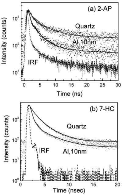
Intensity-time decays of (a) 2-AP and (b) 7-HC on quartz and 10-nm-thick aluminum films.
Figure 8b shows the fluorescence intensity decays of 7-HC on quartz and 10-nm-thick aluminum film substrates. We observed a faster decay of 7-HC on the aluminum surface compared to that on the quartz surface. The amplitude-weighted lifetime on quartz and 10-nm-thick aluminum film is about 1.1 and 0.5 ns, respectively. These reductions of fluorescence lifetimes are in accordance with our previously reported findings and could be well described by the radiating plasmon model.5,12 This is because the dyes are within the near-field of the aluminum nanostructures and couple very efficiently with the particulate aluminum surface, thus inducing radiating plasmons in the aluminum particles. This faster (and hence more efficient) emission from the excited fluorophore–metal complex is the reason behind the observed shortened lifetime. Control measurements on the quartz or aluminum substrates, without the fluorophores (2-AP or 7-HC), yielded almost no signal when observed through the set of band-pass emission filters used to detect the corresponding emission from those fluorophores.
The photophysical properties of a fluorophore is governed by the ratio of magnitude of the radiative decay rate, Γ, with that of the nonradiative decay rates, knr, such as internal conversion and quenching. In general, the emission quantum yield, Φ0 and lifetime τo of a fluorophore are represented by5
| (3) |
| (4) |
We have found that the enhanced fluorescence intensities or, in other words, quantum yields of fluorophores in proximity to metallic nanoparticles or nanostructures could be well described by the following equations:
| (5) |
where Γm and knr′ are radiative and nonradiative rates in the presence of metal particles, respectively. The lifetime of a fluorophore in the presence of metal is decreased by an increased (system) radiative decay rate. By system we mean the excited-state fluorophore–metal complex:
| (6) |
It is apparent from the above equations that in the presence of metal particles or surfaces as radiative decay rate Γm increases, the quantum yield Φm increases, while the emission lifetime, τm, decreases.
Figure 9 shows the dependence of the ratio of amplitude-weighted lifetimes of 2-AP on the thickness of aluminum films. It is important to note that the largest reduction of emission lifetime was observed when the probe 2-AP was on the 10-nm-thick aluminum film. As mentioned earlier, we have also observed the largest enhancement in the emission intensity of both the fluorophores 2-AP and 7-HC on 10-nm-thick particulate aluminum substrates. We believe the shorter lifetimes of both probes observed on an aluminum nanostructured surface are due to an increase in the radiative decay rate, but we cannot rule out quenching of some portion of the population. The amplitude-weighted lifetime displayed a tendency to increase with the thickness of the aluminum film above 10 nm.
Figure 9.
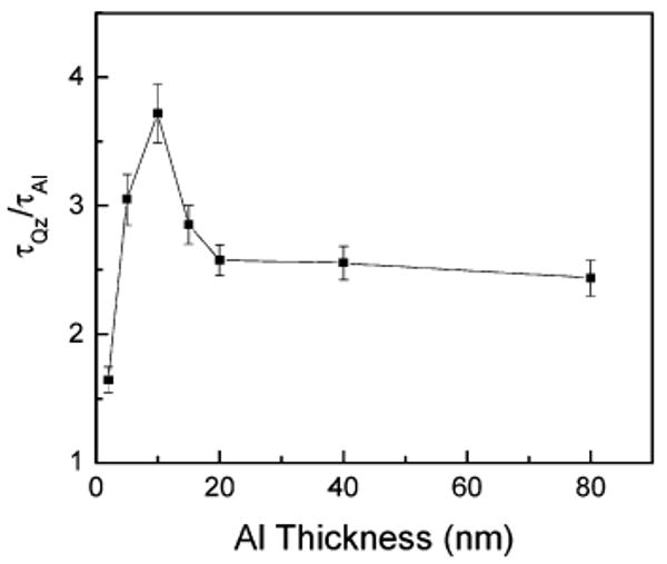
Ratio of amplitude weighted lifetimes of 2-AP on quartz and Al substrates as a function of Al thicknesses.
In many examples of fluorescence-based sensing, it is fluorophore detectability that governs the utility and sensitivity of the sensing approach. In general, the detectability of a fluorophore is determined by two factors: the extent of background emission from the sample and the photostability of the fluorophore. Accordingly, we have made a comparison between the photostability of the two fluorophores on quartz and Al substrates.
Figure 10 presents the photostability of both fluorophores (2-AP and 7-HC) on quartz and particulate aluminum film substrates. Using the same incident excitation power, we observed significantly more fluorescence from the Al nanostructured substrates as compared to the quartz control sample (data not shown). In Figure 10, the incident excitation power on the Al nanostructured films has been attenuated to give the similar initial emission intensity (at time = 0 min) as observed on the quartz substrate. It is apparent from Figure 10 that both probes (2-AP and 7-HC) are more photostable on the 10-nm-thick particulate aluminum substrate as compared to the quartz substrate.
Figure 10.
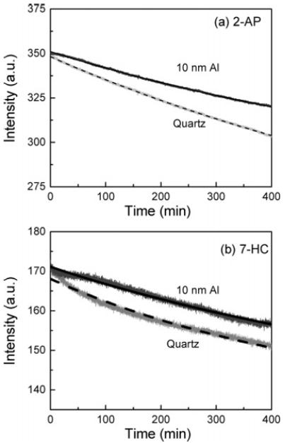
Photostability of (a) 2-AP and (b) 7-HC on quartz and 10-nm Al films.
It is interesting to comment on the total detectability of fluorophores in the presence of the metal nanostructures/particles. While a maximum of 8–9-fold increase in fluorescence intensity is clearly beneficial, a reduced fluorescence lifetime of probes also enables the system to be cycled faster, as the lifetime of a species determines its cyclic rate. Hence, an 8-fold increase in intensity coupled with a 4-fold reduction in lifetime of the probes in proximity to the aluminum nanostructured surfaces provides a significant increase in detectability. In addition, a reduced lifetime also affords for increased fluorophore photostability as there is less time for excited-state photodestructive processes to occur. In total, it appears that the detectability of UV-blue fluorophores can be increased significantly near aluminum particles considering the co-operative effects of enhanced fluorescence intensity, reduced lifetime, and increased photostability on particulate aluminum substrates.
Summary
In this paper, we have introduced particulate aluminum films as substrates for MEF in the ultraviolet-blue spectral region. We investigated the variation in the size of the aluminum nanostruc-tures to identify the optimum conditions for MEF in the ultraviolet-blue spectral region. We have observed a maximum of ∼9-fold increase in emission intensity and a 4-fold reduction in fluorescence lifetime from a DNA base analogue 2-AP in proximity to the aluminum nanostructured surfaces that provide increased detectability when compared to the quartz control. A maximum of ∼6-fold increase in fluorescence intensity and ∼3-fold decrease in lifetime was attained for the probe 7-HC on particulate aluminum films. We have also observed increased photostability of both fluorophores on aluminum substrates. Our results indicate that the observed emission arises due to the near-field metal–fluorophore complex. The observation of MEF on particulate aluminum films suggests the use of these stable nanostructures in surface-localized bioassays. These robust particulate aluminum substrates could be useful in many fluorescence-based assay applications such as DNA arrays as these substrates are very stable in the buffers containing chloride salts compared to the usual silver nanoparticle-based substrates for MEF. UV fluorophores are routinely used to label proteins and membranes. Examples include diphenylhexatriene and its derivatives, pyrenes, dansyl, and anilinonaphthalene-type fluorophores. Based on the results using 2-AP, such fluorophores should also display MEF. The optical properties of aluminum could potentially also be useful for obtaining MEF with intrinsic protein fluorescence. Medical assays and biotechnology applications such as drug discovery frequently utilize surface-localized chemistry. Our results on MEF with particulate aluminum surfaces indicate that the range of wavelengths can be extended down to the ultraviolet. This will provide a wide range of wavelengths for development of multi-analyte assays using different color fluorophores.
Acknowledgments
This work was supported by the National Institutes of Health, NCRR-RR008119 and NIBIB EB-00682, EB-0065211 and NHGRI HG-002655 grants. The authors thank Dr. Wen-An Chiou of Maryland Nanocenter, University of Maryland, College Park, for SEM measurements.
References
- 1.van Dyke K. Luminescence immunoassay and molecular applications. CRC Press; Boca Raton, FL: 1990. [Google Scholar]
- 2.Hemmila A. Application of fluorescence in immunoassays. John Wiley & Sons; New York: 1992. [Google Scholar]
- 3.Walker NJ. Science. 2002;296:557–559. doi: 10.1126/science.296.5567.557. [DOI] [PubMed] [Google Scholar]
- 4.Livak KJ, Flood SJA, Marmaro J, Giusti W, Deetz K. PCR Methods Appl. 1995;4:357–362. doi: 10.1101/gr.4.6.357. [DOI] [PubMed] [Google Scholar]
- 5.Lakowicz JR. Anal Biochem. 2001;298:1–24. doi: 10.1006/abio.2001.5377. [DOI] [PMC free article] [PubMed] [Google Scholar]
- 6.Sokolov K, Chumanov G, Cotton TM. Anal Chem. 1998;70:3898–3905. doi: 10.1021/ac9712310. [DOI] [PubMed] [Google Scholar]
- 7.Chumanov G, Sokolov K, Gregory BW, Cotton TM. J Phys Chem. 1995;99:9466–9471. [Google Scholar]
- 8.Geddes CD, Cao H, Gryczynski I, Gryczynski Z, Fang JY, Lakowicz JR. J Phys Chem A. 2003;107:3443–3449. doi: 10.1021/jp022040q. [DOI] [PMC free article] [PubMed] [Google Scholar]
- 9.Messinger BJ, von Raben KU, Chang RK, Barber PW. Phys Rev B. 1981;24:649–657. [Google Scholar]
- 10.Ray K, Badugu R, Lakowicz JR. J Am Chem Soc. 2006;128:8998–8999. doi: 10.1021/ja061762i. [DOI] [PMC free article] [PubMed] [Google Scholar]
- 11.Ray K, Badugu R, Lakowicz JR. Langmuir. 2006;22:8374–8378. doi: 10.1021/1a061058f. [DOI] [PMC free article] [PubMed] [Google Scholar]
- 12.Lakowicz JR. Anal Biochem. 2005;337:171–194. doi: 10.1016/j.ab.2004.11.026. [DOI] [PMC free article] [PubMed] [Google Scholar]
- 13.Novotny L, Hecht B. Principles of Nano Optics. Cambridge University Press; Cambridge, UK: 2006. [Google Scholar]
- 14.Yguerabide J, Yguerabide EE. Anal Biochem. 1998;262:137–156. doi: 10.1006/abio.1998.2759. [DOI] [PubMed] [Google Scholar]
- 15.Yguerabide J, Yguerabide EE. Anal Biochem. 1998;262:157–176. doi: 10.1006/abio.1998.2760. [DOI] [PubMed] [Google Scholar]
- 16.Anger P, Bharadwaj P, Novotny L. Phys Rev Lett. 2006;96:113002. doi: 10.1103/PhysRevLett.96.113002. [DOI] [PubMed] [Google Scholar]
- 17.Kühn S, Håkanson U, Rogobete L, Sandoghdar V. Phys Rev Lett. 2006;97:017402. doi: 10.1103/PhysRevLett.97.017402. [DOI] [PubMed] [Google Scholar]
- 18.Weitz DA, Garoff S, Gersten JI, Nitzan A. J Chem Phys. 1983;78:5324–5338. [Google Scholar]
- 19.Gryczynski I, Malicka J, Gryczynski Z, Lakowicz JR. Anal Chem. 2004;76:4076–4081. doi: 10.1021/ac040004c. [DOI] [PMC free article] [PubMed] [Google Scholar]
- 20.Taflove A, Hagness SC. Computational Electrodynamics: The Finite-Difference Time-Domain Method. Artech House; Boston: 2000. [Google Scholar]
- 21.Sullivan DM. Electromagnetic simulation using the FDTD method. IEEE Press; New York: 2000. [Google Scholar]
- 22.Yang P, Liou NK. J Opt Soc Am A. 1996;13:2072–2085. [Google Scholar]
- 23.Gray SK, Kupka T. Phy Rev B. 2003;68:045415. [Google Scholar]
- 24.Chang SH, Gray SK, Schatz GC. Opt, Express. 2005;13:3150–3165. doi: 10.1364/opex.13.003150. [DOI] [PubMed] [Google Scholar]
- 25.Taflove A, Brodwin ME. IEEE Trans Microwave Theory Tech. 1975;23:623–630. [Google Scholar]
- 26.Reference Guide for FDTD Solutions™ Release 5.0. 2007. http://www.lumerical.com/fdtd.
- 27.Raether H. Surface Plasmons on Smooth and Rough Surfaces and on Gratings. Springer-Verlag; New York: 1998. [Google Scholar]
- 28.Shadowitz A. The Electromangetic Field. Dover; New York: 1988. [Google Scholar]
- 29.Lakowicz JR. Principles of Fluorescence Spectroscopy. 3rd. Springer; New York: 2006. [Google Scholar]


